EP1601171B1 - Système, procédé pour régler un signal audio - Google Patents
Système, procédé pour régler un signal audio Download PDFInfo
- Publication number
- EP1601171B1 EP1601171B1 EP04102416A EP04102416A EP1601171B1 EP 1601171 B1 EP1601171 B1 EP 1601171B1 EP 04102416 A EP04102416 A EP 04102416A EP 04102416 A EP04102416 A EP 04102416A EP 1601171 B1 EP1601171 B1 EP 1601171B1
- Authority
- EP
- European Patent Office
- Prior art keywords
- signal
- filter
- audio signal
- coefficients
- adjustment parameters
- Prior art date
- Legal status (The legal status is an assumption and is not a legal conclusion. Google has not performed a legal analysis and makes no representation as to the accuracy of the status listed.)
- Expired - Lifetime
Links
- 230000005236 sound signal Effects 0.000 title claims abstract description 81
- 238000000034 method Methods 0.000 title claims abstract description 39
- 238000004891 communication Methods 0.000 claims abstract description 40
- 238000012545 processing Methods 0.000 claims abstract description 19
- 230000004044 response Effects 0.000 claims description 60
- 238000012544 monitoring process Methods 0.000 claims description 3
- 230000001629 suppression Effects 0.000 claims description 3
- 238000007493 shaping process Methods 0.000 description 15
- 238000004422 calculation algorithm Methods 0.000 description 14
- 230000001413 cellular effect Effects 0.000 description 11
- 230000002238 attenuated effect Effects 0.000 description 5
- 238000005259 measurement Methods 0.000 description 4
- 230000000694 effects Effects 0.000 description 3
- 238000004519 manufacturing process Methods 0.000 description 3
- 238000004458 analytical method Methods 0.000 description 2
- 238000004364 calculation method Methods 0.000 description 2
- 230000003247 decreasing effect Effects 0.000 description 2
- 238000010586 diagram Methods 0.000 description 2
- 238000001914 filtration Methods 0.000 description 2
- 238000007667 floating Methods 0.000 description 2
- 238000012986 modification Methods 0.000 description 2
- 230000004048 modification Effects 0.000 description 2
- 238000005070 sampling Methods 0.000 description 2
- 230000003321 amplification Effects 0.000 description 1
- 230000007423 decrease Effects 0.000 description 1
- 238000001514 detection method Methods 0.000 description 1
- 238000005516 engineering process Methods 0.000 description 1
- 230000007613 environmental effect Effects 0.000 description 1
- 238000011156 evaluation Methods 0.000 description 1
- 238000003199 nucleic acid amplification method Methods 0.000 description 1
- 230000001105 regulatory effect Effects 0.000 description 1
Images



Classifications
-
- H—ELECTRICITY
- H04—ELECTRIC COMMUNICATION TECHNIQUE
- H04M—TELEPHONIC COMMUNICATION
- H04M1/00—Substation equipment, e.g. for use by subscribers
- H04M1/60—Substation equipment, e.g. for use by subscribers including speech amplifiers
- H04M1/6016—Substation equipment, e.g. for use by subscribers including speech amplifiers in the receiver circuit
-
- H—ELECTRICITY
- H04—ELECTRIC COMMUNICATION TECHNIQUE
- H04M—TELEPHONIC COMMUNICATION
- H04M1/00—Substation equipment, e.g. for use by subscribers
- H04M1/60—Substation equipment, e.g. for use by subscribers including speech amplifiers
- H04M1/6033—Substation equipment, e.g. for use by subscribers including speech amplifiers for providing handsfree use or a loudspeaker mode in telephone sets
- H04M1/6041—Portable telephones adapted for handsfree use
- H04M1/605—Portable telephones adapted for handsfree use involving control of the receiver volume to provide a dual operational mode at close or far distance from the user
Definitions
- the invention relates to a system and method for adjusting an audio signal, in particular an audio signal generated by a speaker in a communication device.
- an audible audio signal is generated by generating an electrical signal representative of the audible signal and feeding that signal to a speaker.
- Various adjustments can be applied to the audio signal, including changing its volume, pitch and frequency, using known analog and digital signal processing techniques.
- a current feature provides a volume setting which selectively increases and decreases volume of an audio signal generated by the device's speaker.
- the phone's volume setting may be placed at a "high" volume level, to increase the audio signal of the person calling the user.
- the volume setting may be set at a sufficiently high level to enable the user to listen to the audio signal generated by the cellular phone without requiring that the cellular phone be placed immediately near the user's ear. This setting is useful when the user checks his voice mail system.
- Known signal processing techniques provide dynamic monitoring of audio signals to dynamically recognize when an audio signal has excessive distortion and then provide a corrective shaping signal to it to reduce the distortion.
- Such techniques work very well, but use sophisticated evaluation techniques which require a significant amount of signal processing capabilities to implement them in real time. Smaller devices, such as cellular phones, have limited signal processing capabilities, and may not have sufficient capabilities to implement these techniques.
- EP0767570 discloses a system and method for adjusting the audio output signal of a communications device using an equaliser having a variable frequency response.
- the frequency response of the equaliser is changed in accordance with one or more control parameters such as the device's sound volume as set by a user, ambient noise level measured through the device's microphone, information about auxiliaries connected to the device and measurements describing the quality of a wireless connection to the device.
- control parameters such as the device's sound volume as set by a user, ambient noise level measured through the device's microphone, information about auxiliaries connected to the device and measurements describing the quality of a wireless connection to the device.
- control parameters such as a user effected change in the device's audio output signal volume
- control information of the equaliser is changed thereby varying its frequency response.
- a digital signal processor (DSP) controls the equaliser in response to changes in any of the control parameters to so that audio output signal components at certain frequencies are attenuated or amplified according to existing environmental and operating conditions of the communications device.
- US4721923 discloses a basic audio speech amplifier circuit where a high pass filter is selectively applied to an audio signal when the signal is being boosted to a level of distortion. In order to compensate for the loss of energy in the signal produced by the attenuator, the circuit provides a DC boost of the output voltage signal prior to filtering.
- WO2004/004409 discloses a system and method for adjusting the audio output signal of a communications device using an equaliser to at least partially compensate for a non-flat frequency response of a speaker through frequency selective attenuation.
- the system includes means for decreasing frequency selective attenuation when a maximum amplification by an amplifier has already been reached resulting in zero attenuation at all frequencies when a maximum audio output signal volume has been reached.
- the present invention provides a method of adjusting an output audio signal of a communication device, said method comprising performing the steps in said communication device of: obtaining a digitized signal of a signal received at said device, said received signal encoding an audio signal; monitoring for a request to increase a current volume setting to an increased volume level for said output audio signal; and generating an adjusted version of said digitized signal to implement said increased volume level utilizing a digital signal processor (DSP); a processing filter defined in said DSP; and said digitized signal; the method being characterized in that it comprises the steps of: upon determining that said increased volume level is within a predetermined quality threshold, generating an adjusted version of said digitized signal to implement said increased volume level utilizing a predetermined first set of adjustment parameters comprising filter coefficients for said DSP processing filter stored in a memory of said communication device; upon determining that said increased volume level would cause said output audio signal to exceed said predetermined quality threshold, generating an adjusted version of said digitized signal to have an acceptable characteristic for said quality
- DSP digital
- the characteristic may be a volume level of the output audio signal; said quality threshold may be an upper boundary of an audio frequency pass mask; said acceptable characteristic may be a frequency response within an acceptable boundary of said audio frequency pass mask; said filter may be a finite impulse response (FIR) filter; and said first and second sets of adjustment parameters may each be a respective set of coefficients for said FIR filter.
- FIR finite impulse response
- a second set of said adjustment parameters may provide a set of coefficients to adjust said audio signal to comply with said audio frequency pass mask and/or adjust said audio signal to roll off lower frequency components in said audio signal and to further adjust said audio signal to boost higher frequency components in said audio signal.
- the present invention provides a circuit for adjusting an output audio signal of a communication device, said circuit comprising: a module for receiving a signal encoding an audio signal and converting said signal to a digitized signal; a module to accept a request for an increase in a current volume setting to an increased volume level for said output audio signal; a microprocessor adapted to detect when said request for said increase occurs and to generate an adjusted version of digitized signal to implement said increased volume level utilizing a digital signal processor (DSP); a filter; and said digitized signal; and a module to convert said adjusted version of the digitized signal to an analog audio signal and to provide said analog audio signal to a speaker; the circuit being characterized in that said DSP is adapted to determine if said request for said increase at said increased volume level would generate an audio output signal which exceeds a predetermined quality threshold, and, upon determining that said increased volume is within said quality threshold, to select a first set of adjustment parameters comprising filter coefficients for said DSP processing filter stored in a
- the characteristic may be a volume level of the output audio signal; said quality threshold may be an upper boundary of an audio frequency pass mask; said acceptable characteristic may be a frequency response within an acceptable boundary of said audio frequency pass mask; said filter may be a finite impulse response (FIR) filter; and said first and second sets of adjustment parameters may each be a respective set of coefficients for said FIR filter.
- the audio frequency pass mask may be compliant with GSM standards.
- a second set of said adjustment parameters may comprise a set of coefficients to adjust said audio signal to comply with said audio frequency pass mask and/or adjust said audio signal to roll off lower frequency components in said audio signal and to further adjust said audio signal to boost higher frequency components in said audio signal.
- the present invention provides a communications device including a system in accordance with the second aspect.
- the present invention provides a telecommunications network including a communications device in accordance with the third aspect.
- the present invention provides a machine readable medium comprising computer code means executable in a microprocessor of a system in accordance with the second aspect for implementing the method in accordance with the first aspect.
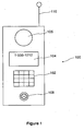
- Figure 1 is a block diagram of a communication device associated with an embodiment
- Figure 2 is a schematic diagram of operational elements associated with the communication device of Fig. 1 ;
- Figure 3 is a frequency response curve illustrating responses for selected output levels of audio signals produced by the communication device of Fig. 1 ;
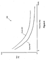
- Figure 4 is a harmonic distortion curve illustrating distortion levels for selected output levels of audio signals produced by the communication device of Fig. 1 ;
- Figure 5 is a flow chart of an algorithm used for adjusting signals used by the operational elements of Fig. 2 .
- communication device 100 is shown.
- User of communication device 100 can establish a call with another person using another device which can communicate with device 100.
- Device 100 may be a telephone, cordless telephone, cellular phone, voice-enabled personal digital assistant or any device providing electronic voice communications.
- the other person may be using a device connected to a PSTN network (not shown). Therein, communications may be established through a cellular network (not shown) associated with device 100 and a PSTN network associated with the device of the other person.
- the other device may be a voice mail system.
- the main interface elements of communication device 100 for its user include: keypad 102, display 104, speaker 106 and microphone 108.
- Speaker 106 generates all audible signals received from the other device.
- Microphone 108 receives all audio signals from the user as he speaks to the other person.
- Speaker 106 can be any type of speaker having appropriate dimensions and performance characteristics to produce an audio signal for device 100.
- antenna 110 is provided to receive and transmit wireless signals for device 100.
- circuit 200 provides facilities to receive and transmit audio signals to and from device 100.
- Circuit 200 comprises microprocessor 202, non-volatile memory 204, digital signal processing (DSP) module 206, radio module 208, antenna 110, coder/decoder (CODEC) 210 and speaker 106.
- DSP digital signal processing
- CDEC coder/decoder
- Microprocessor 202 is the main control element for device 100.
- Algorithm 212 is a program operating on microprocessor 202, effectively providing control for many operations of device 100, including call control, display control and power management.
- Microprocessor 202 has access to memory 204, which is used to store routines, variables and data used by algorithm 212.
- microprocessor 202 is a commercially available microcontroller, such as a microcontroller available from ARM, Motorola and Intel.
- Memory 204 is a flash memory device. Other technologies of non-volatile storage devices known in the art can be used.
- a representative DSP 206 is commercially available from various manufacturers, including Texas Instruments and Analog Devices.
- a representative CODEC 210 is commercially available from Texas Instruments and Analog Devices.
- a representative speaker 106 is commercially available from Philips and Foster.
- antenna I 10 provides a wireless interface to receive and transmit voice signals encoded in radio frequencies to other devices.
- Antenna 110 is connected to radio module 208, which converts received wireless signals 214 received by antenna 110 into electrical signals, which can then be used by the other elements in circuit 200.
- module 208 converts received wireless signals 214 into digital data stream 216, which is a sufficient representation of the audio signal encoded in wireless signal 214.
- data representing digitized audio signals spoken by the user and received by microphone 104 is received by radio module 208 then converted into an electrical signal for antenna 110, which then converts the electrical signal to a radio signal and transmits it to the air.
- Radio module 208 comprises internal circuits and routines known in the art of radio signal processing.
- Digital data stream 216 is provided from radio module 208 to DSP 206, which is programmed to selectively shape the digitized voice signals to effect a required acoustic response properties for sounds meant for reproduction on speaker 106.
- DSP 206 At the heart of DSP 206 is filter 218, which provides an algorithm to process signal inputs (such as data 216) and apply set adjustment coefficients to aspects of the inputs, to produce output data stream 222.
- the adjustment coefficients are preferably provided by data 220 from microprocessor 202 as another set of inputs to DSP 206. With all of the input and coefficient information, DSP 206 uses its internal specialized DSP circuits to efficiently generate output data stream 222.
- output data stream 222 is provided to CODEC 210, which converts stream 216 to analog electrical signal 224, and then provides the electrical signal to speaker 106.
- Speaker 106 converts electrical signal 224 into audio signal 226, which can be heard by user 228.
- cellular phones and other wireless communication devices such as device 100, generally must meet minimal operating performance specifications relating to the quality of audio signals produced by its speaker.
- audio specifications include signal frequency response and loudness rating standards.
- graph 300 is a receive frequency response graph defined under Globale Systems Mobile (GSM) standards.
- GSM Globale Systems Mobile
- the receive frequency response standard mandates that the measured frequency response of a received signal (which is reproduced on speaker 106) falls within a specific mask (measured in dB) for a given frequency range.
- the GSM standard dictates that for a communication device operating at the nominal volume setting, the frequency response of audio signals produced by its speaker must fall between a floating template defined by upper boundary 302 and lower boundary 304.
- Upper boundary 302 is a shaped frequency response curve defining acceptable and unacceptable response levels for given frequencies. For upper boundary 302, at a given frequency if the measured response level is above upper boundary 302, then the measured response fails the specification.
- lower boundary 304 is a shaped frequency response curve defining acceptable and unacceptable response levels for given frequencies.
- the loudness standard is known as the Receive Loudness Rating (RLR).
- RLR Receive Loudness Rating
- the RLR dictates that for a communication device operating at a nominal volume setting, the RLR must be within a certain range. The calculation procedures for RLR are known in the art.
- Frequency response curves 306, 308 and 310 are exemplary responses generated by speaker 106. Each curve represents speaker 106 being driven at one level but having different filter parameters being applied thereto by filter 218 and algorithm 212.
- Frequency response curve 310 is the acoustic frequency response of speaker 106 with no filtering (i.e., with a flat filter response). Since the region of curve 310 about 650 Hz is not compliant with the frequency response mask specification, its audio drive signal requires equalization or shaping to make it compliant.
- Frequency response curve 306 is the acoustic frequency response of speaker 106 with filter parameters applied for the nominal volume setting to provide compliance with the frequency response mask specification. As seen, curve 306 is compliant with the frequency response mask specification throughout its entire frequency range.
- Frequency response curve 308 is the acoustic frequency response of speaker 106 for a different set of filter parameters.
- the region of curve 308 about 300 Hz is not compliant with the frequency response mask specification.
- Curve 308 shows that speaker 106 has lower output levels at the lower frequencies compared to curve 306. This is due to different shaping of the audio signal characteristic of the different set of filter parameters.
- Curve 308 has higher output levels than curve 306 in the frequency region above about 520 Hz. In that region, output values for that speaker have been boosted to compensate for the loss in loudness associated with the low frequency roll-off of the output level of curve 308 relative to curve 306. This compensation ensures that the user experiences the expected change in loudness, as determined by the Receive Loudness Rating (RLR), when the volume setting is switch from one volume level to its adjacent volume level and when filter parameters are switched.
- RLR Receive Loudness Rating
- a related issue to frequency response is the amount of distortion present in the signal.
- a speaker's inherent operational characteristics due to a speaker's inherent operational characteristics, as the volume of a signal reproduced on the speaker is increased, distortion in the audio signal increases.
- Limitations in the speaker include its operating frequency range and power handling capabilities.
- signals in the lower frequencies are distorted first, due to physics relating to transducers.
- a speaker may also have sensitive elements for creating signals having higher frequencies. Accordingly, if the sensitive elements are damaged by high voltage signals, then the signals in the higher frequencies become distorted.
- Graph 400 shows total harmonic distortion (as a percentage) on the y-axis measured against a frequency range (in Hz) on the x-axis.
- Curve 402 shows a representative curve of total harmonic distortion of a speaker driven at its nominal operating level. At its nominal operating level, it may have a frequency response as represented by curve 306 ( Fig. 3 ).
- the embodiment effectively examines the current volume level of the audio signal being reproduced on speaker 106 ( Fig. 2 ), and if the volume level exceeds a certain threshold, then certain aspects of the audio signal are attenuated to reduce the distortion. If the volume level is reduced to below the threshold, then the attenuation is removed. More specifically, when the volume level exceeds a predetermined threshold, device 100 effectively imposes a high-pass filter on the audio signal, thereby attenuating lower frequencies past a cut off band and not attenuating signals in frequencies past the cut off band.
- the shape and cut-off point of the high pass filter may be modified per different performance requirements. In other embodiments, low-pass filters, notch filters, bandpass filters, other types of filters or any combination of filters may be used.
- parameters For a given set of performance requirements, parameters must be established to set when a signal is attenuated and by how much.
- One method of identifying the characteristics is to measure the performance of the given speaker 106 under differing signal levels, by measuring its frequency response and distortion characteristics. The measurements are analyzed to identify volume levels which may produce excessive distortion and the associated frequency responses. Thereafter a cut-off volume level is selected. When the volume level of speaker 106 exceeds the cut-off volume, then signals are attenuated at certain frequencies. The identification of which frequencies require attenuation and what the attenuation amount should be is also determined by analyzing the measurements.
- time domain techniques may be used to implement a signal shaping algorithm.
- Signal shaping in the time domain allows use of DSP techniques to implement its shaping characteristics. Details regarding a digital implementation of the signal shaping is now provided.
- filter 218 is a basic block of DSP 206 and calculates attenuation values (if any) for signals sent to speaker 106.
- its frequency response in the frequency domain is governed by values of coefficients provided to its taps, as filter 218 processes data in the time domain. In programming these tap values, typically floating point numbers may be used. However, as filter 218 is implemented in hardware, the coefficients and the related data are represented as digital data in binary format. The operating guidelines of DSP 206 need to be followed to effect proper implementation of filter 218.
- a Finite Impulse Response (FIR) filter is used for filter 218.
- FIR Finite Impulse Response
- a FIR filter has an impulse response of finite duration.
- the FIR filter uses a series of taps representing samples taken at different time intervals.
- the sampling rate for the embodiment is 8 kHz, providing a period of calculation of 125 us. This sampling rate is reasonable as the audio signals related to device 100 are in the telephone bandwidth of 0 to 3,400 Hz.
- the FIR response uses 32 points.
- the coefficients for the FIR filter may be determined using several known techniques. As noted above, one technique is to conduct frequency measurements and determine a given cut-off frequency and shaping curve. Subsequently, the frequency domain information regarding the shaping curve may be converted to a set of coefficients in the time domain, using known techniques readily available in signal processing simulation software.
- Table A lists two sets of coefficients defined for device 100.
- the values in Table A are stored in non-volatile memory 204 and accessed by algorithm 212.
- Set 1 provides a set of coefficients which equalizes the acoustic response so that it complies with the GSM mask.
- the shaping would convert a response found in curve 310 ( Fig. 3 ) to a response found in curve 306.
- Set 2 provides a set of coefficients which rolls-off lower frequencies to control distortion.
- the shaping would convert curve 310 to curve 308.
- the overall gain between the two sets is adjusted so that a change in volume from one level to its adjacent level still provides the same change in loudness level that the user expects (for example, a 3 dB change).
- a user-selectable volume control is typically provided to ensure the loudness rating can be adjusted to account for the level of the incoming audio signal and the hearing capabilities of the user.
- This volume control is typically implemented in uniform steps; steps of 3 dB per change are common.
- Algorithm 212 controls operation of tonal adjustments made to a signal in view of a particular volume setting.
- the audio output device is selected.
- algorithm 212 determines the current volume setting for device 100 and compares it with a threshold. If the volume is below the threshold, algorithm 212 selects Set 1, per step 504.
- DSP 206 coordinates acceptance of the tap values and the incoming data values in data stream 218.
- step 506 if algorithm 212 detects that the volume level exceeds the threshold, then Set 2 is selected. After either step 504 or 506, algorithm 212 goes to step 508 and checks whether the currently loaded Set of coefficients is different than the selected Set. If the currently loaded Set is different, then step 510 is executed and the selected Set (either Set 1 or 2) is retrieved from memory and provided to DSP 206. Thereafter, the operating cycles for DSP 206 generates the adjusted audio signal (in digital form). Thereafter, at step 512, device 100 waits for a change in volume levels. Upon detection of a change, algorithm 212 returns to step 502.
- the volume level is used to determine which download filter coefficients are to be provided to DSP 206.
- a volume setting of "7”, (in a 0-10 scale where a volume setting of "5" is defined as nominal and each step provides a 3 dB volume steps), is selected as the threshold point.
- Other embodiments may use other volume steps or additional sets of coefficients for different volume levels.
- Other embodiments may use variations on the flow of operations, while still achieving signal shaping, from the algorithm noted above.
- Other embodiments may use more sets of coefficients.
- the embodiment provides an effective and simple shaping routine for potentially distorted signals.
- Other embodiments may use other digital filters, such as an Infinite Impulse Response (IIR) filter, which are known in the art.
- IIR Infinite Impulse Response
- Such other settings include, without limitation: a signal boost for selected signals; volume adjustment; gain adjustment; a programmable gain amplifier (PGA) steps adjustment; side tone frequency adjustment; switching adjustments; specific frequency suppression adjustment; and adjustment for specific microphone parameters.
- PGA programmable gain amplifier
- the above embodiment is useful for tuning speaker performance in production models of device 100.
- different types of speakers 106 may be used in different manufacturing batches. Accordingly, for a given model of speaker 106, the above method may be used to determine one set of performance characteristics and a set of signal shaping parameters are provided for that model.
- the parameters for that model are used to attenuate the volume signals.
- the method is used to determine its set of performance characteristics and signal shaping parameters. Accordingly, different adjustment parameters are provided to device 100 when that second speaker is used.
- the embodiment identifies a characteristic associated with an audio signal and identifies a quality threshold for the characteristic. Adjustment parameters are set for the signals. When the characteristic is exceeded, the DSP is provided with a set of parameters to reduce the unwanted factor associated with the signal to produce an adjusted signal where the unwanted factor is lessened. When the characteristic is not exceeded, the DSP is provided with another set of parameters which may not necessarily provide an output signal which needs to account for the unwanted factor.
- the embodiment monitors for a change in a volume level for a communication device. If the volume level is below a predetermined threshold, then DSP 206 is provided with a set of coefficients to shape the audio signal to conform with an audio frequency pass mask, such as the mask illustrated in Fig. 3 . If the volume level exceeds the threshold, then there may be distortion in the signal. As such, the lower frequency signals in the signal are rolled-off in a preset fashion to reduce the amplitude of the lower frequency signals. This has the effect of lessening any distortion in the signal. However, the rolled-off signal has less loudness associated with it. As such, the signal is boosted in its higher frequencies in a preset fashion to compensate for the removed energy from the signal. The resulting rolled-off and boosted signal provides a signal which mimics a step-wise increase in volume (e.g. a 3dB increase in loudness).
- signals may be step-wise attenuated as volume levels are decreased with an appropriate modification to the signals to ensure compliance with a mask.
Landscapes
- Engineering & Computer Science (AREA)
- Signal Processing (AREA)
- Circuit For Audible Band Transducer (AREA)
- Input Circuits Of Receivers And Coupling Of Receivers And Audio Equipment (AREA)
- Signal Processing Not Specific To The Method Of Recording And Reproducing (AREA)
- Stereo-Broadcasting Methods (AREA)
- Tone Control, Compression And Expansion, Limiting Amplitude (AREA)
- Cable Transmission Systems, Equalization Of Radio And Reduction Of Echo (AREA)
- Telephone Function (AREA)
Claims (15)
- Procédé d'ajustement d'un signal de sortie audio d'un dispositif de communication (100), ledit procédé comprenant la réalisation des étapes suivantes dans ledit dispositif de communication :obtenir un signal numérisé (216) d'un signal (214) reçu au niveau dudit dispositif, ledit signal reçu codant un signal audio ;surveiller la formulation d'une demande d'augmentation du réglage actuel du volume à un niveau de volume supérieur pour ledit signal de sortie audio (226) ; etgénérer une version ajustée (222) dudit signal numérisé (216) afin d'appliquer ledit niveau de volume supérieur à l'aide d'un processeur de signal numérique (DSP) (206) ; un filtre de traitement (218) défini dans ledit DSP ; et ledit signal numérisé ;le procédé étant caractérisé en ce qu'il comprend les étapes consistant à :générer une version ajustée dudit signal numérisé lorsqu'il est déterminé que ledit niveau de volume supérieur se situe dans un seuil de qualité prédéterminé, afin d'appliquer ledit niveau de volume supérieur à l'aide d'un premier ensemble prédéterminé de paramètres d'ajustement comprenant des coefficients de filtrage pour ledit filtre de traitement du DSP (218) stocké dans une mémoire (204) dudit dispositif de communication (100) ;générer une version ajustée dudit signal numérisé lorsqu'il est déterminé que ledit niveau de volume supérieur entraînerait un dépassement dudit seuil de qualité prédéterminé par ledit signal de sortie audio, afin d'obtenir une caractéristique acceptable pour ledit seuil de qualité tout en appliquant ledit niveau de volume supérieur à l'aide d'un second ensemble prédéterminé de paramètres d'ajustement comprenant des coefficients de filtrage pour ledit filtre de traitement du DSP (218) stocké dans ladite mémoire (204) dudit dispositif de communication (100) qui fournit différents niveaux de sortie pour ledit signal de sortie audio à différentes fréquences, comparé audit premier ensemble de paramètres d'ajustement ;convertir ladite version ajustée dudit signal en un signal audio analogique ajusté ; etfournir ledit signal audio analogique ajusté à un haut-parleur dans ledit dispositif.
- Procédé selon la revendication 1, dans lequel :ledit seuil de qualité est une limite supérieure (302) d'un cache de bande passante de fréquence audio (302, 304) ;ladite caractéristique acceptable est une réponse de fréquence (308) comprise dans une limite acceptable dudit cache de bande passante de fréquence audio ;ledit filtre est un filtre à réponse impulsionnelle finie « FIR » (218) ;ledit premier ensemble de paramètres d'ajustement est un premier ensemble de coefficients pour ledit filtre FIR ; etledit second ensemble de paramètres d'ajustement est un second ensemble de coefficients pour ledit filtre FIR.
- Procédé selon la revendication 2, dans lequel ledit second ensemble de paramètres d'ajustement fournit un ensemble de coefficients destinés à ajuster ledit signal audio afin de respecter ledit cache de bande passante de fréquence audio (302, 304).
- Procédé selon l'une quelconque des revendications 1 à 3, dans lequel ledit second ensemble de paramètres d'ajustement fournit un ensemble de coefficients permettant d'ajuster ledit signal audio pour affaiblir les composants basse fréquence dans ledit signal audio.
- Procédé selon la revendication 4, dans lequel ledit second ensemble de paramètres d'ajustement fournit un ensemble de coefficients permettant d'ajuster encore ledit signal audio pour amplifier les composants haute fréquence dans ledit signal audio.
- Procédé selon la revendication 1, dans lequel :ledit seuil de qualité est une limite associée à un des attributs suivants dans ledit signal audio :l'amplification de signal pour des signaux sélectionnés ;l'ajustement de gain ;l'ajustement de la fréquence d'effet local ;des ajustements de commutation ;la suppression des signaux ; etdes ajustements pour un microphone dans ledit dispositif de communication ;ladite caractéristique acceptable est une réponse de fréquence (308) comprise dans une limite acceptable d'un cache de bande passante de fréquence audio (302, 304) ;ledit filtre est un filtre à réponse impulsionnelle finie « FIR » (218) ;ledit premier ensemble de paramètres d'ajustement est un premier ensemble de coefficients pour ledit filtre FIR ; etledit second ensemble de paramètres d'ajustement est un second ensemble de coefficients pour ledit filtre FIR.
- Circuit d'ajustement d'un signal de sortie audio d'un dispositif de communication (100), ledit circuit (200) comprenant :un module (208) permettant de recevoir un signal (214) codant un signal audio et de convertir ledit signal (214) en un signal numérisé (216) ;un module permettant d'accepter une demande d'augmentation du réglage de volume actuel à un niveau de volume supérieur pour ledit signal de sortie audio (226) ;un microprocesseur (202) permettant de détecter quand ladite demande d'augmentation se produit et de générer une version ajustée (222) du signal numérisé (216) pour appliquer ledit niveau de volume supérieur à l'aide d'un processeur de signal numérique (DSP) (206) ; un filtre (218) ; et ledit signal numérisé (216) ; etun module (210) permettant de convertir ladite version ajustée (222) du signal numérisé (216) en un signal audio analogique (224) et de fournir ledit signal audio analogique à un haut-parleur (106) ;le circuit étant caractérisé en ce que ledit DSP (206) est conçu pour déterminer si ladite demande d'augmentation audit niveau de volume supérieur générerait un signal de sortie audio (226) dépassant un seuil de qualité prédéterminé ; et
lorsqu'il est déterminé que ledit volume supérieur est compris dans le seuil de qualité, pour sélectionner un premier ensemble de paramètres d'ajustement comprenant des coefficients de filtrage pour ledit filtre de traitement du DSP (218) stocké dans une mémoire (204) dudit dispositif de communication (100) devant être utilisé par ledit processeur de signal numérique pour générer une version ajustée (222) dudit signal numérisé (216) pour appliquer ledit volume supérieur ; et
lorsqu'il est déterminé que ledit volume supérieur entraînerait un dépassement dudit seuil de qualité par ledit signal audio de sortie, pour sélectionner un second ensemble de paramètres d'ajustement comprenant des coefficients de filtrage pour ledit filtre de traitement du DSP (218) stocké dans ladite mémoire (204) dudit dispositif de communication (100) devant être utilisé par ledit processeur de signal numérique pour générer une autre version ajustée dudit signal numérisé fournissant des niveaux de sortie différents pour ledit signal numérisé à des fréquences différentes comparés à ladite version ajustée afin d'obtenir une caractéristique acceptable pour ledit seuil de qualité lors de l'application dudit volume supérieur. - Circuit selon la revendication 7, dans lequel
ledit seuil de qualité est associé à un cache de bande passante de fréquence audio (302, 304) ;
ladite caractéristique acceptable est une réponse de fréquence (308) dans une limite acceptable dudit cache de bande passante de fréquence audio ;
ledit filtre est un filtre à réponse impulsionnelle finie « FIR » (218) ;
ledit premier ensemble de paramètres d'ajustement est un premier ensemble de coefficients pour ledit filtre FIR ; et
ledit second ensemble de paramètres d'ajustement est un second ensemble de coefficients pour ledit filtre FIR. - Circuit selon la revendication 8, dans lequel ledit cache de bande passante de fréquence audio (302, 304) est conforme aux normes GSM.
- Circuit selon la revendication 9, dans lequel ledit second ensemble de paramètres d'ajustement comprend un ensemble de coefficients destinés à affaiblir les composants basse fréquence dans ledit signal audio.
- Circuit selon la revendication 10, dans lequel ledit second ensemble de paramètres d'ajustement comprend un ensemble de coefficients destinés à amplifier les composants haute fréquence dans ledit signal audio.
- Circuit selon la revendication 7, dans lequel :ledit seuil de qualité est une limite associée à un des attributs suivants concernant ledit signal audio :l'amplification de signal pour des signaux sélectionnés ;l'ajustement de gain ;l'ajustement de la fréquence d'effet local ;des ajustements de commutation ;la suppression des signaux ; etdes ajustements pour un microphone dans ledit dispositif de communication ;ledit filtre est un filtre à réponse impulsionnelle finie « FIR » ;ledit premier ensemble de paramètres d'ajustement est un premier ensemble de coefficients pour ledit filtre FIR ; etledit second ensemble de paramètres d'ajustement est un second ensemble de coefficients pour ledit filtre FIR.
- Dispositif de communication comprenant un circuit selon l'une quelconque des revendications 7 à 12.
- Réseau de télécommunication comprenant un dispositif de communication selon la revendication 13.
- Support lisible par ordinateur comprenant un moyen de codage informatique exécutable dans un microprocesseur (202) d'un circuit (200) selon l'une quelconque des revendications 7 à 12 pour mettre en oeuvre le procédé selon l'une quelconque des revendications 1 à 6.
Priority Applications (8)
| Application Number | Priority Date | Filing Date | Title |
|---|---|---|---|
| DE602004013425T DE602004013425T2 (de) | 2004-05-28 | 2004-05-28 | System und Verfahren zur Einstellung eines Audiosignals |
| EP04102416A EP1601171B1 (fr) | 2004-05-28 | 2004-05-28 | Système, procédé pour régler un signal audio |
| AT04102416T ATE394008T1 (de) | 2004-05-28 | 2004-05-28 | System und verfahren zur einstellung eines audiosignals |
| SG200503142A SG117583A1 (en) | 2004-05-28 | 2005-05-16 | System and method for adjusting an audio signal |
| CA2715742A CA2715742C (fr) | 2004-05-28 | 2005-05-17 | Circuit, systeme et methode de reglage de signal audio |
| CA2507799A CA2507799C (fr) | 2004-05-28 | 2005-05-17 | Systeme et methode de reglage d'un signal audio |
| CN200510074690.6A CN1716764B (zh) | 2004-05-28 | 2005-05-30 | 用于调整音频信号的系统和方法 |
| HK06105493.5A HK1083964B (en) | 2006-05-12 | System and method for adjusting an audio signal |
Applications Claiming Priority (1)
| Application Number | Priority Date | Filing Date | Title |
|---|---|---|---|
| EP04102416A EP1601171B1 (fr) | 2004-05-28 | 2004-05-28 | Système, procédé pour régler un signal audio |
Publications (2)
| Publication Number | Publication Date |
|---|---|
| EP1601171A1 EP1601171A1 (fr) | 2005-11-30 |
| EP1601171B1 true EP1601171B1 (fr) | 2008-04-30 |
Family
ID=34929153
Family Applications (1)
| Application Number | Title | Priority Date | Filing Date |
|---|---|---|---|
| EP04102416A Expired - Lifetime EP1601171B1 (fr) | 2004-05-28 | 2004-05-28 | Système, procédé pour régler un signal audio |
Country Status (6)
| Country | Link |
|---|---|
| EP (1) | EP1601171B1 (fr) |
| CN (1) | CN1716764B (fr) |
| AT (1) | ATE394008T1 (fr) |
| CA (2) | CA2715742C (fr) |
| DE (1) | DE602004013425T2 (fr) |
| SG (1) | SG117583A1 (fr) |
Cited By (1)
| Publication number | Priority date | Publication date | Assignee | Title |
|---|---|---|---|---|
| US8428270B2 (en) | 2006-04-27 | 2013-04-23 | Dolby Laboratories Licensing Corporation | Audio gain control using specific-loudness-based auditory event detection |
Families Citing this family (10)
| Publication number | Priority date | Publication date | Assignee | Title |
|---|---|---|---|---|
| WO2007072280A1 (fr) * | 2005-12-22 | 2007-06-28 | Koninklijke Philips Electronics N.V. | Dispositif et procede destines au traitement de donnees audio |
| EP2625621B1 (fr) * | 2010-10-07 | 2016-08-31 | Concertsonics, LLC | Procédé et système pour améliorer le son |
| CN102291496B (zh) | 2011-09-06 | 2013-08-07 | 华为终端有限公司 | 终端的通话方法及使用该通话方法的终端 |
| EP2632141B1 (fr) * | 2012-02-22 | 2014-10-15 | Dialog Semiconductor B.V. | Post-filtre pour annuleurs d'écho dans le domaine spectral pour gérer des composants d'écho non linéaire |
| KR101196751B1 (ko) * | 2012-04-23 | 2012-11-07 | 엘지전자 주식회사 | 이동 단말기 및 그것의 제어 방법 |
| TWI617135B (zh) * | 2014-12-18 | 2018-03-01 | 緯創資通股份有限公司 | 聲音輸出裝置及其控制方法 |
| CN106126162B (zh) * | 2016-06-16 | 2019-07-19 | Oppo广东移动通信有限公司 | 一种防止音效突变的方法及终端 |
| US10225654B1 (en) * | 2017-09-07 | 2019-03-05 | Cirrus Logic, Inc. | Speaker distortion reduction |
| KR102704825B1 (ko) * | 2018-10-01 | 2024-09-09 | 삼성디스플레이 주식회사 | 표시 장치 |
| CN114464211A (zh) * | 2022-02-16 | 2022-05-10 | 深圳市瑞云科技有限公司 | 一种云游戏音频质量的测试方法 |
Family Cites Families (5)
| Publication number | Priority date | Publication date | Assignee | Title |
|---|---|---|---|---|
| US4644561A (en) * | 1985-03-20 | 1987-02-17 | International Mobile Machines Corp. | Modem for RF subscriber telephone system |
| US4721923A (en) * | 1987-01-07 | 1988-01-26 | Motorola, Inc. | Radio receiver speech amplifier circuit |
| JPH07273840A (ja) * | 1994-03-25 | 1995-10-20 | Nec Corp | 音声帯域制御機能を有する移動電話機 |
| FI99062C (fi) * | 1995-10-05 | 1997-09-25 | Nokia Mobile Phones Ltd | Puhesignaalin taajuuskorjaus matkapuhelimessa |
| AU2002328829A1 (en) * | 2002-07-01 | 2004-01-19 | Nokia Corporation | Mobile communication terminal |
-
2004
- 2004-05-28 DE DE602004013425T patent/DE602004013425T2/de not_active Expired - Lifetime
- 2004-05-28 EP EP04102416A patent/EP1601171B1/fr not_active Expired - Lifetime
- 2004-05-28 AT AT04102416T patent/ATE394008T1/de not_active IP Right Cessation
-
2005
- 2005-05-16 SG SG200503142A patent/SG117583A1/en unknown
- 2005-05-17 CA CA2715742A patent/CA2715742C/fr not_active Expired - Fee Related
- 2005-05-17 CA CA2507799A patent/CA2507799C/fr not_active Expired - Fee Related
- 2005-05-30 CN CN200510074690.6A patent/CN1716764B/zh not_active Expired - Fee Related
Cited By (3)
| Publication number | Priority date | Publication date | Assignee | Title |
|---|---|---|---|---|
| US8428270B2 (en) | 2006-04-27 | 2013-04-23 | Dolby Laboratories Licensing Corporation | Audio gain control using specific-loudness-based auditory event detection |
| US9136810B2 (en) | 2006-04-27 | 2015-09-15 | Dolby Laboratories Licensing Corporation | Audio gain control using specific-loudness-based auditory event detection |
| US9450551B2 (en) | 2006-04-27 | 2016-09-20 | Dolby Laboratories Licensing Corporation | Audio control using auditory event detection |
Also Published As
| Publication number | Publication date |
|---|---|
| DE602004013425D1 (de) | 2008-06-12 |
| SG117583A1 (en) | 2005-12-29 |
| DE602004013425T2 (de) | 2009-06-04 |
| CN1716764A (zh) | 2006-01-04 |
| EP1601171A1 (fr) | 2005-11-30 |
| CA2715742A1 (fr) | 2005-11-28 |
| CA2507799C (fr) | 2010-12-07 |
| CA2715742C (fr) | 2013-12-03 |
| ATE394008T1 (de) | 2008-05-15 |
| HK1083964A1 (en) | 2006-07-14 |
| CN1716764B (zh) | 2010-06-09 |
| CA2507799A1 (fr) | 2005-11-28 |
Similar Documents
| Publication | Publication Date | Title |
|---|---|---|
| US8300848B2 (en) | System and method for adjusting an audio signal | |
| US6011853A (en) | Equalization of speech signal in mobile phone | |
| US6212496B1 (en) | Customizing audio output to a user's hearing in a digital telephone | |
| EP2849458B1 (fr) | Dispositifs, procédés et produits de programme informatique permettant de commander l'intensité acoustique | |
| CN100514989C (zh) | 通信设备话筒增益调节器 | |
| RU2347282C2 (ru) | Система и способ обработки звукового сигнала | |
| US20060126865A1 (en) | Method and apparatus for adaptive sound processing parameters | |
| CN115209292A (zh) | 音频信号补偿方法及装置、耳机、存储介质 | |
| US8645144B2 (en) | Audio signal shaping for playback by audio devices | |
| JP2002536930A (ja) | 適応ダイナミックレンジ最適化サウンドプロセッサ | |
| EP1601171B1 (fr) | Système, procédé pour régler un signal audio | |
| JP2010028515A (ja) | 音声強調装置、携帯端末、音声強調方法および音声強調プログラム | |
| US20060014570A1 (en) | Mobile communication terminal | |
| EP1811660A1 (fr) | Procédé et dispositif pour contrôler automatiquement le gain d'un haut-parleur dans un téléphone mobile | |
| EP1829028A1 (fr) | Procede et appareil utilisant des parametres de traitement sonore adaptatifs | |
| WO2004039126A2 (fr) | Dispositif de radiocommunications mobiles et procede de reglage de caracteristiques sonores | |
| HK1083964B (en) | System and method for adjusting an audio signal | |
| EP2595312A1 (fr) | Circuit de commande de gain automatique et procédé pour la commande de gain automatique | |
| WO2000019686A1 (fr) | Telephone avec dispositif permettant d'ameliorer l'impression de signal subjective en presence de bruit | |
| JP2586847B2 (ja) | 電子電話機 | |
| EP0763903A1 (fr) | Dispositif de communication | |
| KR100905773B1 (ko) | 청력도 기반의 개인별 통화품질 향상방법 및 장치 | |
| JP2002218045A (ja) | 携帯型無線機器の補聴処理装置および携帯型無線機器 | |
| CN114446315A (zh) | 通讯装置及其调整输出侧音的方法 | |
| JP2002182700A (ja) | 動力学で制限されたオーディオシステムのための動力学低減 |
Legal Events
| Date | Code | Title | Description |
|---|---|---|---|
| PUAI | Public reference made under article 153(3) epc to a published international application that has entered the european phase |
Free format text: ORIGINAL CODE: 0009012 |
|
| 17P | Request for examination filed |
Effective date: 20040621 |
|
| AK | Designated contracting states |
Kind code of ref document: A1 Designated state(s): AT BE BG CH CY CZ DE DK EE ES FI FR GB GR HU IE IT LI LU MC NL PL PT RO SE SI SK TR |
|
| AX | Request for extension of the european patent |
Extension state: AL HR LT LV MK |
|
| REG | Reference to a national code |
Ref country code: HK Ref legal event code: DE Ref document number: 1083964 Country of ref document: HK |
|
| AKX | Designation fees paid |
Designated state(s): AT BE BG CH CY CZ DE DK EE ES FI FR GB GR HU IE IT LI LU MC NL PL PT RO SE SI SK TR |
|
| AXX | Extension fees paid |
Extension state: LV Payment date: 20040621 Extension state: HR Payment date: 20040621 Extension state: AL Payment date: 20040621 Extension state: LT Payment date: 20040621 Extension state: MK Payment date: 20040621 |
|
| 17Q | First examination report despatched |
Effective date: 20060606 |
|
| GRAP | Despatch of communication of intention to grant a patent |
Free format text: ORIGINAL CODE: EPIDOSNIGR1 |
|
| GRAS | Grant fee paid |
Free format text: ORIGINAL CODE: EPIDOSNIGR3 |
|
| GRAA | (expected) grant |
Free format text: ORIGINAL CODE: 0009210 |
|
| AK | Designated contracting states |
Kind code of ref document: B1 Designated state(s): AT BE BG CH CY CZ DE DK EE ES FI FR GB GR HU IE IT LI LU MC NL PL PT RO SE SI SK TR |
|
| AX | Request for extension of the european patent |
Extension state: AL HR LT LV MK |
|
| REG | Reference to a national code |
Ref country code: GB Ref legal event code: FG4D |
|
| REG | Reference to a national code |
Ref country code: CH Ref legal event code: EP |
|
| REG | Reference to a national code |
Ref country code: IE Ref legal event code: FG4D Free format text: LANGUAGE OF EP DOCUMENT: FRENCH |
|
| REF | Corresponds to: |
Ref document number: 602004013425 Country of ref document: DE Date of ref document: 20080612 Kind code of ref document: P |
|
| PG25 | Lapsed in a contracting state [announced via postgrant information from national office to epo] |
Ref country code: SI Free format text: LAPSE BECAUSE OF FAILURE TO SUBMIT A TRANSLATION OF THE DESCRIPTION OR TO PAY THE FEE WITHIN THE PRESCRIBED TIME-LIMIT Effective date: 20080430 |
|
| NLV1 | Nl: lapsed or annulled due to failure to fulfill the requirements of art. 29p and 29m of the patents act | ||
| ET | Fr: translation filed | ||
| PG25 | Lapsed in a contracting state [announced via postgrant information from national office to epo] |
Ref country code: BG Free format text: LAPSE BECAUSE OF FAILURE TO SUBMIT A TRANSLATION OF THE DESCRIPTION OR TO PAY THE FEE WITHIN THE PRESCRIBED TIME-LIMIT Effective date: 20080730 Ref country code: PT Free format text: LAPSE BECAUSE OF FAILURE TO SUBMIT A TRANSLATION OF THE DESCRIPTION OR TO PAY THE FEE WITHIN THE PRESCRIBED TIME-LIMIT Effective date: 20080930 Ref country code: ES Free format text: LAPSE BECAUSE OF FAILURE TO SUBMIT A TRANSLATION OF THE DESCRIPTION OR TO PAY THE FEE WITHIN THE PRESCRIBED TIME-LIMIT Effective date: 20080810 Ref country code: FI Free format text: LAPSE BECAUSE OF FAILURE TO SUBMIT A TRANSLATION OF THE DESCRIPTION OR TO PAY THE FEE WITHIN THE PRESCRIBED TIME-LIMIT Effective date: 20080430 Ref country code: NL Free format text: LAPSE BECAUSE OF FAILURE TO SUBMIT A TRANSLATION OF THE DESCRIPTION OR TO PAY THE FEE WITHIN THE PRESCRIBED TIME-LIMIT Effective date: 20080430 |
|
| PG25 | Lapsed in a contracting state [announced via postgrant information from national office to epo] |
Ref country code: PL Free format text: LAPSE BECAUSE OF FAILURE TO SUBMIT A TRANSLATION OF THE DESCRIPTION OR TO PAY THE FEE WITHIN THE PRESCRIBED TIME-LIMIT Effective date: 20080430 Ref country code: AT Free format text: LAPSE BECAUSE OF FAILURE TO SUBMIT A TRANSLATION OF THE DESCRIPTION OR TO PAY THE FEE WITHIN THE PRESCRIBED TIME-LIMIT Effective date: 20080430 |
|
| PG25 | Lapsed in a contracting state [announced via postgrant information from national office to epo] |
Ref country code: MC Free format text: LAPSE BECAUSE OF NON-PAYMENT OF DUE FEES Effective date: 20080531 |
|
| REG | Reference to a national code |
Ref country code: CH Ref legal event code: PL |
|
| PG25 | Lapsed in a contracting state [announced via postgrant information from national office to epo] |
Ref country code: SE Free format text: LAPSE BECAUSE OF FAILURE TO SUBMIT A TRANSLATION OF THE DESCRIPTION OR TO PAY THE FEE WITHIN THE PRESCRIBED TIME-LIMIT Effective date: 20080731 Ref country code: CH Free format text: LAPSE BECAUSE OF NON-PAYMENT OF DUE FEES Effective date: 20080531 Ref country code: CZ Free format text: LAPSE BECAUSE OF FAILURE TO SUBMIT A TRANSLATION OF THE DESCRIPTION OR TO PAY THE FEE WITHIN THE PRESCRIBED TIME-LIMIT Effective date: 20080430 Ref country code: DK Free format text: LAPSE BECAUSE OF FAILURE TO SUBMIT A TRANSLATION OF THE DESCRIPTION OR TO PAY THE FEE WITHIN THE PRESCRIBED TIME-LIMIT Effective date: 20080430 Ref country code: LI Free format text: LAPSE BECAUSE OF NON-PAYMENT OF DUE FEES Effective date: 20080531 |
|
| PG25 | Lapsed in a contracting state [announced via postgrant information from national office to epo] |
Ref country code: BE Free format text: LAPSE BECAUSE OF FAILURE TO SUBMIT A TRANSLATION OF THE DESCRIPTION OR TO PAY THE FEE WITHIN THE PRESCRIBED TIME-LIMIT Effective date: 20080430 Ref country code: RO Free format text: LAPSE BECAUSE OF FAILURE TO SUBMIT A TRANSLATION OF THE DESCRIPTION OR TO PAY THE FEE WITHIN THE PRESCRIBED TIME-LIMIT Effective date: 20080430 Ref country code: SK Free format text: LAPSE BECAUSE OF FAILURE TO SUBMIT A TRANSLATION OF THE DESCRIPTION OR TO PAY THE FEE WITHIN THE PRESCRIBED TIME-LIMIT Effective date: 20080430 |
|
| PLBE | No opposition filed within time limit |
Free format text: ORIGINAL CODE: 0009261 |
|
| STAA | Information on the status of an ep patent application or granted ep patent |
Free format text: STATUS: NO OPPOSITION FILED WITHIN TIME LIMIT |
|
| 26N | No opposition filed |
Effective date: 20090202 |
|
| PG25 | Lapsed in a contracting state [announced via postgrant information from national office to epo] |
Ref country code: EE Free format text: LAPSE BECAUSE OF FAILURE TO SUBMIT A TRANSLATION OF THE DESCRIPTION OR TO PAY THE FEE WITHIN THE PRESCRIBED TIME-LIMIT Effective date: 20080430 Ref country code: IE Free format text: LAPSE BECAUSE OF NON-PAYMENT OF DUE FEES Effective date: 20080528 |
|
| PG25 | Lapsed in a contracting state [announced via postgrant information from national office to epo] |
Ref country code: IT Free format text: LAPSE BECAUSE OF FAILURE TO SUBMIT A TRANSLATION OF THE DESCRIPTION OR TO PAY THE FEE WITHIN THE PRESCRIBED TIME-LIMIT Effective date: 20080430 |
|
| PG25 | Lapsed in a contracting state [announced via postgrant information from national office to epo] |
Ref country code: HU Free format text: LAPSE BECAUSE OF FAILURE TO SUBMIT A TRANSLATION OF THE DESCRIPTION OR TO PAY THE FEE WITHIN THE PRESCRIBED TIME-LIMIT Effective date: 20081101 Ref country code: CY Free format text: LAPSE BECAUSE OF FAILURE TO SUBMIT A TRANSLATION OF THE DESCRIPTION OR TO PAY THE FEE WITHIN THE PRESCRIBED TIME-LIMIT Effective date: 20080430 Ref country code: LU Free format text: LAPSE BECAUSE OF NON-PAYMENT OF DUE FEES Effective date: 20080528 |
|
| PG25 | Lapsed in a contracting state [announced via postgrant information from national office to epo] |
Ref country code: TR Free format text: LAPSE BECAUSE OF FAILURE TO SUBMIT A TRANSLATION OF THE DESCRIPTION OR TO PAY THE FEE WITHIN THE PRESCRIBED TIME-LIMIT Effective date: 20080430 |
|
| PG25 | Lapsed in a contracting state [announced via postgrant information from national office to epo] |
Ref country code: GR Free format text: LAPSE BECAUSE OF FAILURE TO SUBMIT A TRANSLATION OF THE DESCRIPTION OR TO PAY THE FEE WITHIN THE PRESCRIBED TIME-LIMIT Effective date: 20080731 |
|
| REG | Reference to a national code |
Ref country code: DE Ref legal event code: R082 Ref document number: 602004013425 Country of ref document: DE Representative=s name: MERH-IP MATIAS ERNY REICHL HOFFMANN, DE |
|
| REG | Reference to a national code |
Ref country code: DE Ref legal event code: R081 Ref document number: 602004013425 Country of ref document: DE Owner name: BLACKBERRY LIMITED, WATERLOO, CA Free format text: FORMER OWNER: RESEARCH IN MOTION LTD., WATERLOO, ONTARIO, CA Effective date: 20140925 Ref country code: DE Ref legal event code: R082 Ref document number: 602004013425 Country of ref document: DE Representative=s name: MERH-IP MATIAS ERNY REICHL HOFFMANN, DE Effective date: 20140925 Ref country code: DE Ref legal event code: R082 Ref document number: 602004013425 Country of ref document: DE Representative=s name: MERH-IP MATIAS ERNY REICHL HOFFMANN PATENTANWA, DE Effective date: 20140925 |
|
| REG | Reference to a national code |
Ref country code: FR Ref legal event code: PLFP Year of fee payment: 13 |
|
| PGFP | Annual fee paid to national office [announced via postgrant information from national office to epo] |
Ref country code: DE Payment date: 20160527 Year of fee payment: 13 Ref country code: GB Payment date: 20160527 Year of fee payment: 13 |
|
| PGFP | Annual fee paid to national office [announced via postgrant information from national office to epo] |
Ref country code: FR Payment date: 20160530 Year of fee payment: 13 |
|
| REG | Reference to a national code |
Ref country code: DE Ref legal event code: R119 Ref document number: 602004013425 Country of ref document: DE |
|
| GBPC | Gb: european patent ceased through non-payment of renewal fee |
Effective date: 20170528 |
|
| REG | Reference to a national code |
Ref country code: FR Ref legal event code: ST Effective date: 20180131 |
|
| PG25 | Lapsed in a contracting state [announced via postgrant information from national office to epo] |
Ref country code: DE Free format text: LAPSE BECAUSE OF NON-PAYMENT OF DUE FEES Effective date: 20171201 Ref country code: GB Free format text: LAPSE BECAUSE OF NON-PAYMENT OF DUE FEES Effective date: 20170528 |
|
| PG25 | Lapsed in a contracting state [announced via postgrant information from national office to epo] |
Ref country code: FR Free format text: LAPSE BECAUSE OF NON-PAYMENT OF DUE FEES Effective date: 20170531 |