EP1601236A2 - Gargerät mit einer Kühleinheit - Google Patents
Gargerät mit einer Kühleinheit Download PDFInfo
- Publication number
- EP1601236A2 EP1601236A2 EP05104314A EP05104314A EP1601236A2 EP 1601236 A2 EP1601236 A2 EP 1601236A2 EP 05104314 A EP05104314 A EP 05104314A EP 05104314 A EP05104314 A EP 05104314A EP 1601236 A2 EP1601236 A2 EP 1601236A2
- Authority
- EP
- European Patent Office
- Prior art keywords
- heat
- cooking appliance
- heat pipe
- cooling unit
- appliance according
- Prior art date
- Legal status (The legal status is an assumption and is not a legal conclusion. Google has not performed a legal analysis and makes no representation as to the accuracy of the status listed.)
- Withdrawn
Links
Images

Classifications
-
- H—ELECTRICITY
- H05—ELECTRIC TECHNIQUES NOT OTHERWISE PROVIDED FOR
- H05B—ELECTRIC HEATING; ELECTRIC LIGHT SOURCES NOT OTHERWISE PROVIDED FOR; CIRCUIT ARRANGEMENTS FOR ELECTRIC LIGHT SOURCES, IN GENERAL
- H05B6/00—Heating by electric, magnetic or electromagnetic fields
- H05B6/02—Induction heating
- H05B6/10—Induction heating apparatus, other than furnaces, for specific applications
- H05B6/12—Cooking devices
- H05B6/1209—Cooking devices induction cooking plates or the like and devices to be used in combination with them
- H05B6/1245—Cooking devices induction cooking plates or the like and devices to be used in combination with them with special coil arrangements
- H05B6/1263—Cooking devices induction cooking plates or the like and devices to be used in combination with them with special coil arrangements using coil cooling arrangements
-
- F—MECHANICAL ENGINEERING; LIGHTING; HEATING; WEAPONS; BLASTING
- F24—HEATING; RANGES; VENTILATING
- F24C—DOMESTIC STOVES OR RANGES ; DETAILS OF DOMESTIC STOVES OR RANGES, OF GENERAL APPLICATION
- F24C15/00—Details
- F24C15/006—Arrangements for circulation of cooling air
Definitions
- the invention is based on a cooking appliance with a cooling unit according to the preamble of claim 1.
- From DE 198 17 197 C2 is formed by an induction hob generic Cooking appliance with a cooling unit for cooling power electronic components and known by inducers of the cooktop.
- the cooling unit has a radial fan and a arranged in the air flow of the radial fan heat sink profile for cooling.
- the object of the invention is, in particular, a generic cooking appliance to provide with a cooling unit, by means of targeted and particularly effective heat individual components with a high energy density can be dissipated.
- the task is achieved by the features of claim 1, while advantageous Refinements and developments of the invention the dependent and dependent claims can be removed.
- the invention is based on a cooking appliance, in particular a cooktop, with a Cooling unit for cooling at least one component.
- the cooling unit has at least one heat pipe.
- a heat pipe should be understood in this context a unit, within a medium which is essentially responsible for the heat transport is arranged, in a heat receiving area of the heat pipe for evaporation and in a opposite the heat absorption area generally higher heat dissipation area the heat pipe is provided for condensation, wherein the medium or the energy carrier preferably with regard to the existing in the particular application Temperature range is selected.
- the heat in particular even in low installation spaces, targeted and particularly effective from individual components be discharged to a high energy density and transported to another area.
- the heat pipe can at least largely without movably mounted components and at least be carried out largely maintenance-free, which simply ensures a long service life can be achieved with low maintenance costs.
- the heat pipe can be different, the expert appears reasonable designs having different cross-sectional areas, for example, the heat pipe formed by one or more tubular and / or plate-shaped components
- the shape of the heat pipe may also be in at least one of its extensions be executed differently, for example, the heat pipe in its longitudinal extent be executed with different cross-sectional areas or outer surfaces, so that in the heat dissipation area over a particularly large outer surface of the heat the heat pipe can be advantageously dissipated, etc.
- the Substantially responsible medium can be used for heat absorption Heat release area and from the heat release area to the heat receiving area the same Channel or it can be provided separate channels with low or can also be arranged with greater spatial distance, so that, for example a component between the channels can be arranged.
- flow direction of the medium in the channels can within the heat pipe be provided different flow deflections and / or check valves.
- the heat pipe in its shape, especially in space conditions, customizable, for example, by these at least partially from a
- manually made by a fitter of manually deformable material such as made of a simply plastically or elastically deformable material, e.g. made of copper, or made of an elastically or plastically deformable plastic, etc.
- various components that appear appropriate to the person skilled in the art can be used be cooled within the cooking appliance, but particularly advantageous components or Units with a relatively small surface area and high heat development, such as for example, a magnetron of a microwave device and in particular electronic units, such as power electronics units of an induction hob, triacs, etc.
- the electronic units can be particularly compact due to the possibility of targeted cooling, especially with low height, designed, in confined spaces arranged and operated with a high performance, whereby existing space, especially in cooktops, can be used advantageously.
- the heat can be within the cooking appliance of the temperature-critical to be cooled Unit in different, which appears appropriate to the expert temperature-critical Regions within the cooking device out as well as at least partially from the Cooking device are discharged.
- the heat pipe is particularly advantageous with a heat consumer coupled, which makes good use of the heat energy and total Energy can be saved. It should under a heat consumer all Understood units by means of which uses the heat for a specific purpose can be.
- the heat consumer can be formed by different units, such as from a water heater, a warming drawer, a cooking chamber, etc., particularly advantageous, however, from a hot plate, which advantageously in an upper Region of the cooking appliance can be arranged so that constructively simply a positive Slope from the heat receiving area of the heat pipe to the heat dissipation area The heat pipe and the heat over a large area effectively achieved from the cooking appliance can be dissipated.
- the cooking appliance a fan, which is provided for heat removal from the heat pipe, whereby structurally simple achieved a particularly effective heat dissipation from the heat pipe and in particular also the heat from an upper heat release area the heat pipe to a relative to the heat dissipation area further down heat consumer can be performed.
- at least one additional function is assigned to the fan, such as the cooling of other components, etc., may be additional Components, assembly costs and costs are at least reduced.
- the heat pipe is intended, one for a cooking operation to heat provided airflow, for example, one by free convection resulting air flow or in particular a generated by a fan airflow, for the extraction of vapors and / or for the supply of fresh air in one Cooking chamber serves, etc., whereby the output from the heatpipe heat energy makes sense used and total energy can be saved.
- a thermal conductivity ⁇ higher than 45 W / mK which is essentially the thermal conductivity of steel corresponds, and particularly advantageously has a thermal conductivity ⁇ higher than 74 W / mK, which essentially corresponds to the thermal conductivity ⁇ of iron, such as with a heat conducting medium made of brass with a thermal conductivity ⁇ of 111 W / mK, of aluminum with a thermal conductivity ⁇ of 220 W / mK, of copper with a Thermal conductivity ⁇ of 384 W / mK or with a heat transfer agent from a person skilled in the art as meaningful appearing alloy, the heat can constructively simple with few additional components from the heat pipe in a desired area effectively passed become.
- the heat from the heat pipe in addition or alternatively by means of free convection or by means of others which appears to the skilled person to make sense Heat dis
- the Increased flexibility and, in particular, a desired operating temperature in the too Cooling unit advantageously set, i. controlled and / or regulated.
- the Adjustment unit can be made of different, the expert appears reasonable units be formed, such as by a unit for changing the slope the heat pipe and / or a unit for throttling the currents within the Heatpipe etc.
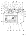
- the stove has an oven with one in one Cooker 29 arranged oven muffle 30, which together with a oven door 31 limits a cooking chamber, which forms a further heat consumer 20.
- Each of the induction cookers 25, 26, 27, 28 has a power electronics unit 15, 16, 17, 18, below a glass ceramic plate 32 each in the region of a not closer illustrated inductor of the induction cookers 25, 26, 27, 28 is arranged.
- the Induction hob has a cooling unit 10 for cooling the power electronics units 15, 16, 17, 18, which according to the invention has four heat pipes 11, 12, 13, 14.
- the one of the hot plate facing induction cookers 25, 28 assigned Heatpipes 11, 14 are formed by tubular components, each with a first End are coupled to one of the power electronics units 15, 18 and starting from these directed upward with a second end to an underside of the heat consumer 19 are formed hot plate from glass ceramic coupled ( Figures 1 and 2).
- In operation of the induction cookers 25, 28 evaporates in the area of the power electronics units 15, 18 coupled ends of the heatpipes 11, 14 a in the heatpipes 11, 14 and arranged on the occurring temperatures of the power electronics units 15, 18 tuned medium, takes heat from the power electronics units 15, 18 up, rises in the vapor state up to the with the hot plate coupled ends, in the area of the medium condenses and heat emits the hotplate. Subsequently, the medium flows back in the liquid state to the lower ends, coupled to the power electronics units 15, 18, thereon following evaporation again.
- the heat transfer via the heat pipes 11, 14 is in each case by means of one of a throttle unit Adjustment unit 23, 24 formed adjustable. From an operator can by means of a by a rotary knob formed actuating means 33, via a control unit 34th and via the adjusting units 23, 24, the heat transfer from the power electronics units 15, 18 are controlled via the heat pipes 11, 14 to the hot plate, wherein is always ensured via the control unit 34 that regardless of the setting of the Operator a predetermined limit temperature of the power electronics units 15, 18th is not exceeded. If the limit temperature is reached, are via the control unit 34 primarily the power electronics units 15, 18 cooled. To the temperature of To be able to adjust the hotplate flexibly and in particular around the hotplate also be able to use without the induction cookers 25, 28 are used are two additional electrical heating elements 36, 37 are provided, by means of which the Hot plate can be heated.
- the the hot plates facing away from the induction hobs 26, 27 assigned Heatpipes 12, 13 are also formed by tubular components, each with a first end to one of the power electronics units 16, 17 are coupled and from this starting upwards with a second end to a channel 35th a ventilation system of the oven are coupled ( Figures 1 and 3).
- Heatpipes 12, 13 a arranged in the heat pipes 12, 13 and on the occurring Temperatures of the power electronics units 16, 17 tuned medium decreases Heat from the power electronics units 16, 17 increases in the vapor state up to the coupled to the channel 35 ends in the area of the medium condenses and gives off heat to the channel 35. Subsequently, the medium flows in the liquid State back to the lower, coupled to the power electronics units 16, 17 Ends to be subsequently evaporated again.
- the channel 35 extends from an opening 38 along a front side of the hearth an upper, the hot plate facing away from the longitudinal edge of the hearth housing 29 and from this to a fan 21 of the ventilation system.
- the fan 21 is on the one hand provided, heat from the channel 35, in particular from coupling points of the heat pipes 12, 13 to the channel 35 and thus dissipate from the heat pipes 12, 13, and the other for generating an intended for a recirculation mode of the oven air flow in the oven.
- the fan 21 is used Furthermore, in individual operating conditions of the oven the cooking chamber via the channel 35 supply a fresh air stream 22.
- the provided for a particular cooking operation of the oven fresh air stream 22 via the Heatpipes 12, 13 heated, and an undesirable decrease in temperature in the cooking chamber can at least be reduced.
- the formed of an aluminum alloy with a thermal conductivity ⁇ of about 200 W / mK Channel 35 serves in addition to the guidance of the fresh air stream 22 as a heat conducting means 40, can be dissipated via the heat from the heat pipes 12, 13 by heat conduction.
Landscapes
- Engineering & Computer Science (AREA)
- Chemical & Material Sciences (AREA)
- Combustion & Propulsion (AREA)
- Mechanical Engineering (AREA)
- General Engineering & Computer Science (AREA)
- Physics & Mathematics (AREA)
- Electromagnetism (AREA)
- Electric Stoves And Ranges (AREA)
- Cookers (AREA)
- Induction Heating Cooking Devices (AREA)
Abstract
Description
- Fig. 1
- einen Herd schräg von oben,
- Fig. 2
- einen schematisch dargestellten ersten Ausschnitt einer Kühleinheit des Herds aus Fig. 1 mit einer zu einer Warmhalteplatte führenden Heatpipe und
- Fig. 3
- einen schematisch dargestellten zweiten Ausschnitt der Kühleinheit des Herds aus Fig. 1 mit einer zu einem Kanal führenden Heatpipe.
- 10
- Kühleinheit
- 11
- Heatpipe
- 12
- Heatpipe
- 13
- Heatpipe
- 14
- Heatpipe
- 15
- Elektronikeinheit
- 16
- Elektronikeinheit
- 17
- Elektronikeinheit
- 18
- Elektronikeinheit
- 19
- Wärmeverbraucher
- 20
- Wärmeverbraucher
- 21
- Lüfter
- 22
- Luftstrom
- 23
- Einstelleinheit
- 24
- Einstelleinheit
- 25
- Induktionskochstelle
- 26
- Induktionskochstelle
- 27
- Induktionskochstelle
- 28
- Induktionskochstelle
- 29
- Herdgehäuse
- 30
- Backofenmuffel
- 31
- Backofentür
- 32
- Glaskeramikplatte
- 33
- Betätigungsmittel
- 34
- Steuereinheit
- 35
- Kanal
- 36
- Heizelement
- 37
- Heizelement
- 38
- Öffnung
- 39
- Heizelement
- 40
- Wärmeleitmittel
Claims (13)
- Gargerät, insbesondere Kochmulde, mit einer Kühleinheit (10) zur Kühlung wenigstens eines Bauteils, dadurch gekennzeichnet, dass die Kühleinheit (10) zumindest eine Heatpipe (11, 12, 13, 14) aufweist.
- Gargerät nach Anspruch 1, dadurch gekennzeichnet, dass das zu kühlende Bauteil von einer Elektronikeinheit (15, 16, 17, 18) gebildet ist.
- Gargerät nach einem der vorhergehenden Ansprüche, dadurch gekennzeichnet, dass die Heatpipe (11, 12, 13, 14) mit einem Wärmeverbraucher (19, 20) gekoppelt ist.
- Gargerät nach Anspruch 3, dadurch gekennzeichnet, dass der Wärmeverbraucher (19) von einer Warmhalteplatte gebildet ist.
- Gargerät nach einem der vorhergehenden Ansprüche, gekennzeichnet durch einen Lüfter (21), der zur Wärmeabführung aus der Heatpipe (12, 13) vorgesehen ist.
- Gargerät nach Anspruch 5, dadurch gekennzeichnet, dass dem Lüfter (21) zumindest eine weitere Funktion zugeordnet ist.
- Gargerät zumindest nach Anspruch 3, dadurch gekennzeichnet, dass die Heatpipe (12, 13) dazu vorgesehen ist, einen für einen Garbetrieb vorgesehenen Luftstrom (22) zu erwärmen.
- Gargerät nach einem der vorhergehenden Ansprüche, dadurch gekennzeichnet, dass die Heatpipe (12, 13) mit wenigstens einem Wärmeleitmittel (40) gekoppelt ist.
- Gargerät nach Anspruch 8, dadurch gekennzeichnet, dass das Wärmeleitmittel (40) bei einer Referenztemperatur von 20°C eine höhere Wärmeleitfähigkeit λ als 45 W/mK aufweist.
- Gargerät nach Anspruch 9, dadurch gekennzeichnet, dass das Wärmeleitmittel (40) bei einer Referenztemperatur von 20°C eine höhere Wärmeleitfähigkeit λ als 74 W/mK aufweist.
- Gargerät nach einem der vorhergehenden Ansprüche, dadurch gekennzeichnet, dass ein Wärmetransport über die Heatpipe (11, 14) mittels einer Einstelleinheit (23, 24) einstellbar ist.
- Herd mit einer Kochmulde nach einem der vorhergehenden Ansprüche.
- Verfahren zur Kühlung wenigstens eines Bauteils eines Gargeräts, insbesondere einer Induktionskochmulde, mit einer Kühleinheit (10), dadurch gekennzeichnet, dass die Kühleinheit (10) wenigstens eine Heatpipe (11, 12, 13, 14) aufweist, mittels der die Wärme aus dem Bauteil abgeführt wird.
Applications Claiming Priority (2)
| Application Number | Priority Date | Filing Date | Title |
|---|---|---|---|
| DE102004025915 | 2004-05-27 | ||
| DE200410025915 DE102004025915A1 (de) | 2004-05-27 | 2004-05-27 | Gargerät mit einer Kühleinheit |
Publications (2)
| Publication Number | Publication Date |
|---|---|
| EP1601236A2 true EP1601236A2 (de) | 2005-11-30 |
| EP1601236A3 EP1601236A3 (de) | 2006-05-17 |
Family
ID=34939921
Family Applications (1)
| Application Number | Title | Priority Date | Filing Date |
|---|---|---|---|
| EP05104314A Withdrawn EP1601236A3 (de) | 2004-05-27 | 2005-05-20 | Gargerät mit einer Kühleinheit |
Country Status (2)
| Country | Link |
|---|---|
| EP (1) | EP1601236A3 (de) |
| DE (1) | DE102004025915A1 (de) |
Cited By (10)
| Publication number | Priority date | Publication date | Assignee | Title |
|---|---|---|---|---|
| EP2306092A2 (de) | 2009-10-02 | 2011-04-06 | BSH Bosch und Siemens Hausgeräte GmbH | Gargerät mit einer sich im Betrieb erwärmenden Komponente sowie Verfahren zum Kühlen einer solchen Komponente |
| EP2306093A2 (de) | 2009-10-02 | 2011-04-06 | BSH Bosch und Siemens Hausgeräte GmbH | Gargerät mit einer sich im Betrieb erwärmenden Komponente und einem Kühlluftgebläse sowie Verfahren zum Kühlen einer sich im Betrieb erwärmenden Komponente eines Gargeräts |
| WO2011086506A3 (de) * | 2010-01-18 | 2011-09-29 | BSH Bosch und Siemens Hausgeräte GmbH | Hausgerätvorrichtung |
| EP2531003A3 (de) * | 2011-06-02 | 2013-01-16 | General Electric Company | Kühlkit für ein Induktionskochfeld |
| EP2306534A3 (de) * | 2009-10-02 | 2013-03-13 | BSH Bosch und Siemens Hausgeräte GmbH | Hausgerät mit einer sich im Betrieb erwärmenden Komponente und einer Kühlvorrichtung sowie Verfahren zum Kühlen einer sich im Betrieb erwärmenden weiteren Komponente eines Hausgeräts |
| DE102014008443A1 (de) | 2014-06-06 | 2015-12-31 | E.G.O. Elektro-Gerätebau GmbH | Induktionskochfeld |
| EP3447389A1 (de) * | 2017-08-25 | 2019-02-27 | Vestel Elektronik Sanayi ve Ticaret A.S. | Kochvorrichtung |
| EP3477209A1 (de) * | 2017-10-27 | 2019-05-01 | Whirlpool Corporation | Ofen mit einem bilderfassungsgerät |
| US11672056B2 (en) * | 2018-03-23 | 2023-06-06 | Lg Electronics Inc. | Induction heating device having improved cooling structure |
| WO2025025668A1 (zh) * | 2023-07-28 | 2025-02-06 | 广东合胜厨电科技有限公司 | 一种带烹饪装置的集成灶 |
Families Citing this family (3)
| Publication number | Priority date | Publication date | Assignee | Title |
|---|---|---|---|---|
| DE102015103812A1 (de) * | 2015-03-16 | 2016-09-22 | Miele & Cie. Kg | Vorrichtung mit einer Kochfeldeinrichtung sowie Verfahren zu dessen Betrieb |
| DE102020215494A1 (de) | 2020-12-08 | 2022-06-09 | Wilhelm Bruckbauer | Vorrichtung zum Erwärmen von Speisen |
| DE102024209733A1 (de) * | 2024-10-04 | 2026-04-09 | BSH Hausgeräte GmbH | Gargerät mit Kühlung eines Elektronikbauteils |
Family Cites Families (9)
| Publication number | Priority date | Publication date | Assignee | Title |
|---|---|---|---|---|
| US3831578A (en) * | 1973-07-11 | 1974-08-27 | Westinghouse Electric Corp | Range exterior surface cooling device |
| JPS5795529A (en) * | 1980-12-05 | 1982-06-14 | Matsushita Electric Ind Co Ltd | Gas appliance |
| JPS5795530A (en) * | 1980-12-05 | 1982-06-14 | Matsushita Electric Ind Co Ltd | Gas appliance |
| DE3544039A1 (de) * | 1985-11-08 | 1987-05-27 | Erich Poehlmann | Heiz- und/oder kochvorrichtung mit einem waermespeicherblock |
| JPH03192686A (ja) * | 1989-12-21 | 1991-08-22 | Mitsubishi Electric Corp | 電磁調理器 |
| JPH06327553A (ja) * | 1993-05-19 | 1994-11-29 | Matsushita Electric Ind Co Ltd | 炊飯器 |
| JPH07241236A (ja) * | 1994-03-03 | 1995-09-19 | Sanyo Electric Co Ltd | 電磁誘導加熱炊飯器 |
| DE19540408A1 (de) * | 1995-10-30 | 1997-05-07 | Herchenbach Wolfgang | Kochsystem |
| TWM240615U (en) * | 2003-03-17 | 2004-08-11 | Shuttle Inc | Combination structure of CPU heat dissipating device and power supply |
-
2004
- 2004-05-27 DE DE200410025915 patent/DE102004025915A1/de not_active Withdrawn
-
2005
- 2005-05-20 EP EP05104314A patent/EP1601236A3/de not_active Withdrawn
Cited By (18)
| Publication number | Priority date | Publication date | Assignee | Title |
|---|---|---|---|---|
| EP2306092A3 (de) * | 2009-10-02 | 2018-01-03 | BSH Hausgeräte GmbH | Gargerät mit einer sich im Betrieb erwärmenden Komponente sowie Verfahren zum Kühlen einer solchen Komponente |
| EP2306093A2 (de) | 2009-10-02 | 2011-04-06 | BSH Bosch und Siemens Hausgeräte GmbH | Gargerät mit einer sich im Betrieb erwärmenden Komponente und einem Kühlluftgebläse sowie Verfahren zum Kühlen einer sich im Betrieb erwärmenden Komponente eines Gargeräts |
| DE102009045296A1 (de) | 2009-10-02 | 2011-04-07 | BSH Bosch und Siemens Hausgeräte GmbH | Gargerät mit einer sich im Betrieb erwärmenden Komponente und einem Kühlluftgebläse sowie Verfahren zum Kühlen einer sich im Betrieb erwärmenden Komponente eines Gargeräts |
| DE102009045297A1 (de) | 2009-10-02 | 2011-04-07 | BSH Bosch und Siemens Hausgeräte GmbH | Gargerät mit einer sich im Betrieb erwärmenden Komponente sowie Verfahren zum Kühlen einer sich im Betrieb erwärmenden Komponente eines Gargeräts |
| EP2306534A3 (de) * | 2009-10-02 | 2013-03-13 | BSH Bosch und Siemens Hausgeräte GmbH | Hausgerät mit einer sich im Betrieb erwärmenden Komponente und einer Kühlvorrichtung sowie Verfahren zum Kühlen einer sich im Betrieb erwärmenden weiteren Komponente eines Hausgeräts |
| EP2306092A2 (de) | 2009-10-02 | 2011-04-06 | BSH Bosch und Siemens Hausgeräte GmbH | Gargerät mit einer sich im Betrieb erwärmenden Komponente sowie Verfahren zum Kühlen einer solchen Komponente |
| EP2306093A3 (de) * | 2009-10-02 | 2018-01-03 | BSH Hausgeräte GmbH | Gargerät mit einer sich im Betrieb erwärmenden Komponente und einem Kühlluftgebläse sowie Verfahren zum Kühlen einer sich im Betrieb erwärmenden Komponente eines Gargeräts |
| WO2011086506A3 (de) * | 2010-01-18 | 2011-09-29 | BSH Bosch und Siemens Hausgeräte GmbH | Hausgerätvorrichtung |
| EP2531003A3 (de) * | 2011-06-02 | 2013-01-16 | General Electric Company | Kühlkit für ein Induktionskochfeld |
| US9125244B2 (en) | 2011-06-02 | 2015-09-01 | General Electric Company | Induction cooktop cooling kit |
| DE102014008443A1 (de) | 2014-06-06 | 2015-12-31 | E.G.O. Elektro-Gerätebau GmbH | Induktionskochfeld |
| EP3447389A1 (de) * | 2017-08-25 | 2019-02-27 | Vestel Elektronik Sanayi ve Ticaret A.S. | Kochvorrichtung |
| EP3477209A1 (de) * | 2017-10-27 | 2019-05-01 | Whirlpool Corporation | Ofen mit einem bilderfassungsgerät |
| US10591218B2 (en) | 2017-10-27 | 2020-03-17 | Whirlpool Corporation | Oven having an imaging device |
| US11231230B2 (en) | 2017-10-27 | 2022-01-25 | Whirlpool Corporation | Oven having an imaging device |
| US11619451B2 (en) | 2017-10-27 | 2023-04-04 | Whirlpool Corporation | Oven having an imaging device |
| US11672056B2 (en) * | 2018-03-23 | 2023-06-06 | Lg Electronics Inc. | Induction heating device having improved cooling structure |
| WO2025025668A1 (zh) * | 2023-07-28 | 2025-02-06 | 广东合胜厨电科技有限公司 | 一种带烹饪装置的集成灶 |
Also Published As
| Publication number | Publication date |
|---|---|
| EP1601236A3 (de) | 2006-05-17 |
| DE102004025915A1 (de) | 2005-12-22 |
Similar Documents
| Publication | Publication Date | Title |
|---|---|---|
| EP1601236A2 (de) | Gargerät mit einer Kühleinheit | |
| DE102017213582B4 (de) | Lüftervorrichtung für ein Elektrogerät, Elektrogerät und Verfahren zur Steuerung derselben | |
| DE60125894T2 (de) | Heizssystem für Mikrowellenofen | |
| DE4433814A1 (de) | Kraftfahrzeug | |
| DE102006015379A1 (de) | Auspuffwärme-Wiedergewinnungseinrichtung | |
| CH658761A5 (de) | Elektrische heizvorrichtung fuer kochherde mit einer kochplatte aus glaskeramik. | |
| WO2004085925A1 (de) | Verfahren zum betreiben eines backofens | |
| EP2526343A2 (de) | Hausgerätvorrichtung | |
| DE102020121633B4 (de) | Induktionskochfeld | |
| DE102006007379B4 (de) | Gargerät mit Combi-Dämpfer, Pizzaofen und Energiespeicher | |
| EP0833108B1 (de) | Anordnung mit einem Backofen und einer Kochmulde | |
| EP3223586A1 (de) | Kochfeldvorrichtung | |
| WO2008064993A1 (de) | Heizvorrichtungsanordnung | |
| DE4322946A1 (de) | Mikrowellengerät mit Strahlungsheizkörper außerhalb des Garraumes | |
| DE102009045297A1 (de) | Gargerät mit einer sich im Betrieb erwärmenden Komponente sowie Verfahren zum Kühlen einer sich im Betrieb erwärmenden Komponente eines Gargeräts | |
| EP3430324B1 (de) | Temperierkörper-anordnung mit flexiblen betriebsarten | |
| EP1431670A2 (de) | Gehäuse für ein Gargerät | |
| DE10122210A1 (de) | Anzeigevorrichtung | |
| DE3307342A1 (de) | Kombinationsherd, vorzugsweise fuer mobile wohneinheiten | |
| EP1643808B1 (de) | Ofen zur Garbehandlung von Lebensmitteln | |
| DE102022106372A1 (de) | Gargerät mit Zustromkanal und Rückstromkanal für einen Heißgasstrom | |
| DE102007046044B4 (de) | Dunstabzugshaube | |
| EP3011879A1 (de) | Küchenmaschine mit kühleinrichtung | |
| DE69509300T2 (de) | Vorrichtung zum Reduzieren der Kondensierung im Garraum eines Mikrowellenherdes | |
| DE102011052267A1 (de) | Deckenhallenheizsystem mit brennwerttechnik |
Legal Events
| Date | Code | Title | Description |
|---|---|---|---|
| PUAI | Public reference made under article 153(3) epc to a published international application that has entered the european phase |
Free format text: ORIGINAL CODE: 0009012 |
|
| AK | Designated contracting states |
Kind code of ref document: A2 Designated state(s): AT BE BG CH CY CZ DE DK EE ES FI FR GB GR HU IE IS IT LI LT LU MC NL PL PT RO SE SI SK TR |
|
| AX | Request for extension of the european patent |
Extension state: AL BA HR LV MK YU |
|
| PUAL | Search report despatched |
Free format text: ORIGINAL CODE: 0009013 |
|
| AK | Designated contracting states |
Kind code of ref document: A3 Designated state(s): AT BE BG CH CY CZ DE DK EE ES FI FR GB GR HU IE IS IT LI LT LU MC NL PL PT RO SE SI SK TR |
|
| AX | Request for extension of the european patent |
Extension state: AL BA HR LV MK YU |
|
| 17P | Request for examination filed |
Effective date: 20061117 |
|
| AKX | Designation fees paid |
Designated state(s): AT BE BG CH CY CZ DE DK EE ES FI FR GB GR HU IE IS IT LI LT LU MC NL PL PT RO SE SI SK TR |
|
| 17Q | First examination report despatched |
Effective date: 20080721 |
|
| RAP1 | Party data changed (applicant data changed or rights of an application transferred) |
Owner name: BSH HAUSGERAETE GMBH |
|
| STAA | Information on the status of an ep patent application or granted ep patent |
Free format text: STATUS: THE APPLICATION IS DEEMED TO BE WITHDRAWN |
|
| 18D | Application deemed to be withdrawn |
Effective date: 20151201 |