EP1601276B1 - Ensemble de couvercle de toilette - Google Patents
Ensemble de couvercle de toilette Download PDFInfo
- Publication number
- EP1601276B1 EP1601276B1 EP04717558A EP04717558A EP1601276B1 EP 1601276 B1 EP1601276 B1 EP 1601276B1 EP 04717558 A EP04717558 A EP 04717558A EP 04717558 A EP04717558 A EP 04717558A EP 1601276 B1 EP1601276 B1 EP 1601276B1
- Authority
- EP
- European Patent Office
- Prior art keywords
- hinge
- seat
- stud
- locking
- groove
- Prior art date
- Legal status (The legal status is an assumption and is not a legal conclusion. Google has not performed a legal analysis and makes no representation as to the accuracy of the status listed.)
- Expired - Lifetime
Links
Images



Classifications
-
- A—HUMAN NECESSITIES
- A47—FURNITURE; DOMESTIC ARTICLES OR APPLIANCES; COFFEE MILLS; SPICE MILLS; SUCTION CLEANERS IN GENERAL
- A47K—SANITARY EQUIPMENT; ACCESSORIES THEREFOR, e.g. TOILET ACCESSORIES
- A47K13/00—Seats or covers for all kinds of closets
- A47K13/12—Hinges
Definitions
- the invention relates to a toilet cover assembly including at least a seat and optionally a cover and a hinge arrangement including two studs adapted to be mounted mutually spaced on a toilet bowl in an upright position and two blocks provided with receiving holes for receiving the studs, said blocks each including a first hinge member of hinge connection provided between the blocks and the seat and comprising a hinge pin member and a hinge eye member, the other hinge member thereof being firmly secured to the seat or the cover, said hinge connections defining an axis of rotation perpendicular to the studs, the hinge members being mutually pivotal about said axis between positions corresponding to the lowered and raised position of the seat.
- a toilet cover assembly is known from document US 4.079.471 .
- US 6.101 . 640 discloses toilet seat assembly of the above type, wherein the studs are in releasable snap engagement with the receiving holes of the blocks, the snap engagement being provided by means of a spring-loaded ball arranged in the studs and engaging a corresponding radial recess in the receiving hole.
- US 4.367. 567 discloses a toilet cover assembly of the above type provided with a hinge shaft arranged in the blocks and being pivotal by means of an operating handle between a position, in which it locks the blocks to the pins and a release position.
- the object of the invention is to provide a toilet cover assembly of the above type, in which the blocks are securely locked to the studs in the lowered position of the seat and releasable therefrom without using a separate tool.
- each stud and hinge connection have co-acting locking means being in mutual locking engagement in a first relative pivot range between the first and the second hinge members (ie a first pivot range of the seat or the cover) to prevent the blocks (and thus the seat or cover) from being detached from the studs, said first pivot range including the pivot position corresponding to the lowered position of the seat or the cover, and in a second relative pivot position or pivot range between the first and second hinge members said locking means being in mutual releasable engagement or disengagement to allow detachment of the blocks (and thus the seat or cover) from the studs, said co-acting locking means being a peripheral groove in said studs and a displaceable locking member arragend in an opening in said blocks.
- the mutual locking engagement of the locking means in the first relative pivot range which includes the pivot position corresponding to the lowered position of the seat, prevents a detachment of the blocks from the studs and thus a removal of the seat in its lowered position, in which position the seat is subjected to the highest load.
- the blocks are easily detachable from the studs in the second relative pivot position by exerting an axially upward force on the block in relation to the studs.
- the studs have an advantageous circular cross-section and are provided with a circumferential groove. As a result it is not necessary to adopt measures for positioning the studs pivotally correctly on the toilet bowl.
- the co-acting locking means may include a peripheral groove provided in the stud, especially a circumferential groove, a locking member displaceably arranged in an opening provided in the blocks, said opening radially ending in the receiving hole of the blocks, and a cam means arranged on the second hinge member and provided with a cam face having a first cam face portion co- acting with the locking member in the first pivot range of the second hinge member so as to retain the locking member in locking engagement with the groove of the stud and a second cam face portion allowing the locking member to be released from its engagement position in a second pivot position or pivot range of the second hinge member.
- a spring means acting on the locking member in the direction towards its engagement position is provided.
- the locking member engages the groove in any pivot position of the second hinge member and an engagement portion of the locking member and the groove of the stud are provided with surfaces co-acting so as to displace the locking member out of its engagement position, when the block is subjected to an axially outward force, whereby the block may be released from the stud in the second pivot position of the second hinge member when subjected to a first outward releasing force.
- This embodiment of the invention is advantageous in that the block is always secured to the stud by means of a force corresponding to the first releasing force, thus preventing an unintentional detachment of the block from the pin in the release position of the seat.
- the embodiment is also advantageous in that it provides an audible click as the locking member snaps into engagement with the groove when the block is mounted on the stud, thus ensuring that the block is mounted correctly on the stud.
- the spring means may be firmly secured to the locking member, optionally integrally formed therewith, eg by means of the spring wire.
- the cam face of the cam means may have a third pivot position or pivot range of the second hinge member, in which it co-acts with the spring means such that a releasing force in excess of the first releasing force is required to detach the block from the stud.
- the said third pivot position or pivot range is advantageously chosen adjacent the second pivot position or pivot range.
- the said relative pivot positions seen in relation to the position of the seat may in principle may chosen freely except for the pivot position corresponding to the lowered position of the seat having to be within the first pivot range. It is, however, preferred that the first pivot range covers the majority of the pivot range between the lowered and raised positions of the seat. It is furthermore preferred that the second pivot range allowing the block to be released from the stud is within a range corresponding to the raised position of the seat, eg the seat being turned 80 to 100' upwards from its lowered position.
- first hinge member provided on the block may be a hinge pin member and the second hinge member being firmly secured to the seat may be a hinge eye member.
- the cam means may be an annular member on the hinge eye member circumscribing the hinge pin and provided with cam faces extending axially in relation to the axis of rotation. This allows for a compact design of the block by placing the axis of rotation such that it intersects the axis of the stud.
- the spring means may be a spring washer arranged around the hinge pin and between the locking member and the cam face.
- the spring means may be provided in a diametrically through-going recess in the hinge pin member.
- the first hinge member provided on the block may be a hinge eye member and the second hinge member being firmly secured to the seat may be a hinge pin member.
- cam means on the hinge pin member may be provided with cam faces radially extending in relation to the axis of rotation.
- the first hinge member provided on the block is a hinge eye member and the second hinge member being firmly secured to the seat is a hinge pin member, the axis of rotation being arranged such that the hinge pin member intersects the receiving hole of the block and thus the stud tangentially and that in the intersecting area with the receiving hole the hinge pin member and the stud are provided with a recess and a groove, respectively, shaped such that the groove and the non-recessed area of the hinge pin member form the co-acting locking means.
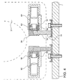
- FIG. 1 is a sectional view through the hinge axis of a first embodiment of a toilet cover assembly according to the invention seen in direction towards the front portion of the seat of the cover, respectively.
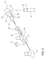
- Fig. 2 is an isometric exploded view of parts of the toilet cover assembly shown in Fig. 1
- Fig. 3 shows in a similar view as in Fig. 1 a second embodiment of the toilet cover assembly, the seat and cover being shown in their lowered position.
- Fig. 4 shows in a similar view as in Fig. 3, the seat and cover being shown in their raised position
- Fig. 5 is an isometric exploded view of parts of the toilet cover assembly shown in Figs. 3 and 4
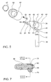
- Fig. 6 is an isometric exploded view of parts of a third embodiment of a toilet cover assembly according to the invention
- Fig. 7 is a horizontal sectional view through the hinge axis of the toilet cover assembly shown in Fig. 6, the parts thereof being shown in an assembled state
- Fig. 8 is a sectional view along the line VIII-VIII in Fig. 7, and wherein the seat and cover are also shown, the seat being in its lowered position, whereas it in Figs. 6 and 7 is shown in its raised position
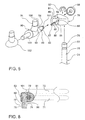
- Fig. 9 is a vertical sectional view through a fourth embodiment of a toilet cover assembly according to the invention
- Fig. 10 is an isometric exploded view of parts of the toilet cover assembly shown in Fig. 9.
- the toilet cover assembly shown in Figs. 1 and 2 includes a seat 1 and a cover 2 which by means of a hinge arrangement are adapted to be mounted on a toilet bowl 3.
- the hinge arrangement includes two brackets 4 each being provided with a bracket plate 5 and a bracket stud 6 extending perpendicularly from the bracket plate 5.
- the bracket is secured by the bracket plate in a known manner to the toilet bowl 4 by means of a screw/nut connection of which only the screw is shown.
- the bracket stud 6, which has a circular cross section, is provided with a circumferential groove 7 adjacent its upper end.
- the bracket stud 6 is provided with a bevelling 8 at its upper end.
- the hinge arrangement further includes a block 9 with a head 14 provided with a receiving hole 10 for receiving the upper end of the bracket stud 6.
- Each block 9 is provided with a hinge pin 11 projecting from the head 14.
- FIG. 2 in which the seat and the cover are not shown, it is indicated that the seat hinge eye 12 and the cover hinge eye 13 are secured to the seat and the cover, respectively, by means of screwing.
- a shoulder 15 is provided between the head 14 and hinge pin 11 of the block 9.
- the end face 16 of the seat hinge eye 12 facing the head 14 is retained in engagement with the shoulder 15 by means of a locking ring 17 arranged in a groove in the hinge pin.
- a depression 18 is provided in the end face 16.
- An annular disc 19 is provided in this depression, said disc being firmly secured to the bottom of the depression of the seat hinge eye 12, eg by adhesion. A portion of the disc 19 has been cut away such that a cavity is formed thereby at the bottom of the depression 18. This cavity does not appear from Fig. 1.
- a spring washer 20 is provided on the annular disc 19.
- a bore 21 is provided extending into the receiving hole 10 of the block.
- a locking pin 22 is displaceably arranged in the bore 21. At a first end 24 the locking pin 22 rests on the spring washer 20 and at a second end 23 the locking pin 22 extends into the circumferential groove 7 of the bracket stud 6.
- the disc 19 supports the spring washer 20 in the area on which the first end 24 of the pin 22 rests.
- the second end 23 of the pin 22 is retained in non-releasable engagement with the circumferential groove 7 of the bracket stud 6.
- the cut-away portion of the annular disc 19 is situated opposite the pin 22, as shown in Fig. 2, in which the seat is shown in its raised position.
- the annular disc 19 does thus not support the spring washer 20.
- the spring washer bends outwards and downwards into the cavity formed at the bottom of the depression 18 and the cut-away portion of the annular disc 19.
- the annular disc 19 thus forms a cam means, the surface or cam face thereof facing the pin defining a locking position, in which the pin is retained in locking engagement with the groove of the stud, the cut-away portion thereof forming a second cam face, where the pin can be brought out of and into engagement with the groove.
- the force required for disengaging the locking pin depends on the position of the first end 24 of the pin in the cut-away portion.
- the force which the spring washer exerts on the pin is thus lowest in the middle of the cut-away portion and increases gradually towards the ends thereof, ie. in the direction towards the cam face of the disc.
- the force required for pulling the seat upwards to remove the blocks from the studs is also lowest when the pin is positioned in the middle of the cut-away portion and increases gradually towards the cam face of the disc, where a release no longer is possible.
- the toilet cover assembly shown in Figs. 3-5 includes a seat 31 and a cover 32 pivotally connected to a toilet bowl 33 by means of a hinge arrangement including two mutually spaced apart brackets 34 each having a bracket plate 35 and a bracket stud 36 projecting vertically from the plate.
- the bracket studs 36 have a circular cross section and are provided with a circumferential groove 37 adjacent their upper ends and a bevelling 38 at their upper ends.
- the hinge arrangement further includes a block 39 with a block head 44 provided with a receiving hole 40 for receiving the stud 36.
- a hinge pin 41 projects from the head 44.
- a shoulder 45 is provided between the head 44 and the hinge pin 41.
- the hinge pins jointly define the axis of rotation of the hinge arrangement.
- the hinge pin 41 is provided with a diagonal recess 50 extending parallel to the receiving hole 40. The bottom of the recess is in the same plane as the shoulder 45. An opening 51 extending to the receiving hole 40 is provided in the bottom.
- the opening 51 is arranged to be flush with the groove 37, when the receiving hole of the block is arranged on the stud 36.
- a locking means in form of a locking pin 52 is displaceably received in the opening 51.
- the locking pin 52 is connected with a L-shaped spring 53 being attached to the bottom of the block at its upper end, as shown by means of the screw 54.
- An engagement end 55 of the locking pin 52 extends into the receiving hole 40 and thus into the groove 37 of the stud 36 when the stud is received in the receiving hole 40.
- a sleeve 46 is pivotally arranged on the hinge pin 41, said sleeve being retained in axial direction between the shoulder 45 and a locking ring 47 engaged in an annular groove 48 in a portion 49 of the hinge pin of a reduced diameter.
- the locking ring 47 abuts the outer face of an inner annular rib 56 on the sleeve 46.
- the surface of the rib 56 axially facing the head 44 is shaped as an annular cam face with an axially protruding portion 58 and an axially recessed portion 57. This cam face is not visible in Fig. 5.
- the protruding cam face portion 58 does, however, appear from Fig. 3, while the recessed cam face portion 57 appears from Fig. 4.
- the seat 31 is provided with two aligned and mutually spaced apart receiving openings 42 and 43.
- the sleeve 46 of a block 39 is received non-pivotally, the sleeve 46 being provided with a projection 59 received in a corresponding groove 60 in the openings 42 and 43, respectively.
- the seat 31 is thus pivotally arranged on the hinge pins 41 via the sleeves 46.
- the toilet cover assembly is further provided with rotational dampers for damping the movement of the seat and cover from their raised to their lowered position.
- the dampers 61,62 each has a shaft 63 of a non-circular cross section and a damper housing provided with a first portion 64 of a circular cross section and a second portion 65, wherein the circular cross section is provided with two opposed plane faces providing the second portion 65 with a non-circular cross section.
- the shaft 63 of the first damper 61 is non-pivotally received in the diagonal recess 50 of the hinge pin 41 shown on the right-hand side in the figures.
- the damper housing extends through an opening 66 in the seat 31 having an area of a cross section corresponding to the second non-circular area 65 of the damper housing such that the damper housing is interlocked with the seat 31.
- the damper housing further extends into a blind hole 67 in the cover 32, said blind hole having a diameter corresponding to that of the dam- per housing.
- the housing of the first damper thus forms the hinge axis for the cover 32.
- the damper 61 shown on the right-hand side in Figs. 3 and 4 thus provides a damping of the seat 31, but no damping of the cover 32.
- the damper 62 shown on the left-hand side in Figs. 3 and 4 has the same shape as the damper 61. However, its damper shaft is non-pivotally retained in the diagonal recess 50 of the hinge pin 41.
- the damper housing extends through a through-going opening 68 in the seat 31 of the same diameter as the damper housing, while the second non-rotational-symmetrical portion 65 of the damper housing extends into a blind hole 70 of a corresponding cross section in the cover 32.
- the damper 62 shown on the left-hand side in Figs. 3 and 4 thus provides a damping of the cover 32, but no damping of the seat 31.
- the recessed cam face portion 57 of the cam face is, however, positioned opposite the inner end 69 of the locking pin 52 (confer Fig. 4) such that the locking pin 52 is axially outwardly displaced in a corresponding manner as explained with reference to the embodiment shown in Figs. 1 and 2, when the seat and thus the block 39 are subjected to an axially upward force in relation to the stud 36.
- the seat 31 and the cover 32 may be detached from the toilet bowl, when the seat is in a substantially vertical position.
- the locking pin automatically engages the groove 37, when the receiving holes 40 of the blocks are made to re-engage the bracket studs 36.
- the third embodiment of a toilet cover assembly according to the invention shown in Figs. 6-8 further includes a seat 71, a cover 72 and two brackets 74, of which only one is shown in the figures, said brackets being adapted to be secured to a toilet bowl.
- the brackets 74 each have a not-shown bracket plate with a bracket stud 76.
- the bracket stud is provided with a circumferential groove 77 adjacent its upper end and a bevelling 78 at its upper end.
- the hinge arrangement further includes a block 79 with a receiving hole 80 for receiving the stud 76.
- the block is shaped as a hinge eye member provided with a hinge bore 81 extending perpendicular to the receiving hole 80.
- the hinge bore 81 is offset in such a manner in relation to the receiving hole 80 that its inner periphery 82 is substantially tangent to the inner periphery 83 of the receiving hole 80.
- the block 79 is provided with an axial groove 84. The said groove 84 thus runs into the receiving hole 80.
- the groove 84 runs into the receiving hole 80 in an area corresponding to the groove 77 of the stud 76, when the stud 76 is received in the receiving hole 80.
- a spring 85 is provided in the axial groove 84, said spring made of bent spring wire and provided with a rounded end 86 extending into the receiving hole 80 and thus into the groove of the stud 76 when the stud is received in the receiving hole 80.
- the spring 85 is provided with two legs 87 inserted in corresponding holes 88 in a shoulder face 89 on the block 79. It should furthermore be noted that the spring does not extend beyond the said shoulder face 89.
- Two interspaced hinge pin members 90 are connected to the seat 71.
- the hinge pin member 90 is provided with a threaded connecting part 91 by means of which it is firmly secured to the seat 71.
- the hinge pin member 90 further has a shoulder forming a transition to a hinge pin 92.
- the hinge pin 92 has a first portion 93 with a first large diameter and a second portion 94 with a second small diameter.
- the hinge bore 81 in the block has a bore portion 95 corresponding to the second portion 94, confer Fig. 7.
- the second portion 94 of the hinge pin 93 projects out of the block 79 and the block is axially retained to the hinge pin member 90 between the shoulder 89 of the hinge pin member and a locking ring 97 arranged in a groove in the projecting second end portion 94 of the hinge pin.
- An end cap 98 is attached to the projecting hinge pin end.
- a cam means is provided between the first and the second portions 93,94 of the hinge pin 92, said cam means being provided with a cam face having a first cam face portion 99 of a diameter corresponding to the first hinge pin portion 93, and a second cam face portion 100 of a diameter corresponding to the second hinge pin portion 94.
- An inclined edge face 101 is provided between the two cam face portions 99 and 100.
- the first cam face portion 99 having a large diameter is positioned immediately opposite the spring 85.
- the end portion 86 of the spring engaging the groove 77 of the stud 76 is thus prevented from disengaging the groove.
- the locking end portion 86 of the spring may be disengaged from the groove 77 of the stud 76 by applying an axially upward force to the block 79 in relation to the stud 76.
- This pivot position of the hinge pin member 90 and thus of the seat is shown in Fig. 7.
- the cam face portion provided with the inclined edge face 101 passes over the spring 85.
- a continuously decreasing portion of the first cam face portion 99 of a large diameter supports the spring 85 when the hinge pin member 90 is turned in the above direction.
- the lever arm of the spring between the locking end face 86 of the spring and the point supported by the first cam face portion 99 of a large diameter increases gradually. Consequently, the force to be exerted on the block 79 for detaching it from the stud 76 decreases gradually until the second cam face portion 100 of a small diameter is positioned opposite the spring.
- this embodiment of the invention allows the block 79 to be removed from the stud 76 in substantially any pivot position of the seat 71 except the lowered position thereof.
- this embodiment of the invention allows the block 79 to be removed from the stud 76 in substantially any pivot position of the seat 71 except the lowered position thereof.
- by increasing the peripheral extent of the first cam face portion 99 it is possible to reduce the pivot range in which the block and thus the seat can be removed.
- cover 72 is pivotally connected to the hinge pin member 90 by means of a cover hinge eye 102 firmly secured to the seat and pivotally arranged on a cover hinge pin 103 provided on the hinge pin member 90 and extending in opposite direction of the hinge pin 93.
- the embodiment of a toilet cover assembly shown in Figs. 9 and 10 is provided with a seat 111 and a cover 112 and two interspaced brackets 114 adapted to be secured to the toilet bowl 113.
- Each bracket includes a stud 116 extending upwards from a bracket plate 115.
- the bracket stud is provided with a circumferential groove 117 adjacent its upper end and a bevelling 118 at its upper end.
- the hinge arrangement further includes a block 119 formed as a hinge eye member and provided with a receiving hole 120 for receiving the stud 116 and a hinge bore 121 arranged perpendicular thereto.
- the hinge bore 121 intersects the block 119 such that a portion thereof extends through the receiving hole 120 and portion thereof is positioned outside the receiving hole 120.
- the axis of the hinge bore extends substantially tangentially to the periphery of the receiving hole.
- the diameter of the hinge bore further substantially corresponds to the diameter of the circumferential groove 117 on the stud 116. In the mounted state of the block 119 on the stud, the groove is positioned opposite the hinge bore 121.
- Each hinge pin member has a head 123 provided with a threaded fastening means 124 by means of which the hinge pin member 122 is secured to the seat 111.
- a hinge pin 125 extends axially from the head 123.
- the hinge pin 125 has an outer diameter corresponding to the hinge bore 121 and extends therethrough.
- the hinge pin 125 is axially retained to the block by means of a locking ring 126 engaging an annular groove in an end portion of the hinge pin 125 projecting from the hinge bore 121.
- An cap 128 is attached to the projecting hinge pin end portion.
- the hinge pin 125 In the area, in which the hinge pin intersects the receiving hole 120, the hinge pin 125 is provided with a recess 129 extending over slightly more than 180°. Put differently, in the said area the hinge pin 125 is shaped as a sector of a circle extending slightly less than 180° when seen in cross-section.
- the recess 129 is positioned opposite the receiving hole 120.
- the hinge block and thus the seat 111 may be removed from stud 116.
- the area 130 of the hinge pin 125 having a cross-section shaped as a sector of a circle, extends into the receiving hole 120 and thus into the groove 117 of the stud when the block 119 is arranged on the stud 116. Consequently the block 119 and thus the seat is secured to the stud 116, when the seat is not in its raised position.
- the hinge pin members 122 are provided with a cover hinge pin 131 opposite the hinge pin 125.
- the cover hinge pins 131 are received in corresponding bores in the cover hinge eyes 133 of which only one is shown, said cover hinge eyes 133 being secured to the cover 112, the cover hinge eyes 133 being provided with a threaded fastening means 134 by means of which they are secured to the cover.
Landscapes
- Health & Medical Sciences (AREA)
- Public Health (AREA)
- Toilet Supplies (AREA)
- Vehicle Waterproofing, Decoration, And Sanitation Devices (AREA)
Claims (10)
- Ensemble de couvercle de toilettes comprenant au moins un siège (1; 31; 71; 111) et, de façon optionnelle, un couvercle (2; 32; 72; 112) et un agencement formant charnière comprenant deux tenons (6; 36; 76; 116) adaptés pour être montés, de façon mutuellement espacée, sur une cuvette de toilettes (3; 33; 113) dans une position droite et deux blocs (9; 39; 79; 119) munis de trous de réception (10; 40; 80; 120) pour recevoir les tenons, lesdits blocs comprenant chacun un premier élément d'articulation d'une connexion formant charnière prévue entre les blocs et le siège et comprenant une élément de broche d'articulation (11; 41; 92; 125) et un élément d'oeil d'articulation (12; 46; 81; 121), son autre élément d'articulation étant fermement fixé sur le siège ou sur le couvercle, lesdites connexions formant charnière définissant un axe de rotation perpendiculaire aux tenons, les éléments d'articulation étant mutuellement pivotants autour dudit axe entre des positions correspondant à la position abaissée et soulevée du siège, caractérisé en ce que chaque tenon (6; 36; 76; 116) et chaque connexion formant charnière possèdent des moyens de blocage complémentaires étant en engagement mutuel de blocage dans un premier intervalle de pivotement relatif entre les premier et second éléments d'articulation, c'est-à-dire un premier intervalle du siège ou du couvercle, afin d'empêcher les blocs (9; 39; 79; 119), et ainsi le siège ou couvercle, d'être détaché des tenons (6; 36; 76; 116), ledit premier intervalle de pivotement comprenant la position de pivot correspondant à la position abaissée du siège ou du couvercle, et dans une seconde position relative de pivot ou intervalle de pivotement entre les premier et second élément d'articulation, lesdits moyens de blocage étant en désengagement ou en engagement mutuel amovible pour permettre une libération des blocs (9; 39; 79; 119), et ainsi du siège ou du couvercle, à partir des montants (6; 36; 76; 116), lesdits moyens de blocage complémentaires étant une rainure périphérique (7; 37; 77) dans lesdits tenons et un élément déplaçable de blocage (22; 52; 86) agencé dans une ouverture (21; 51) dans lesdits blocs.
- Ensemble de couvercle de toilettes selon la revendication 1, caractérisé en ce que la rainure périphérique (7; 37; 77) est une rainure de circonférence dans le tenon (6; 36; 76), et l'élément de blocage (22; 52; 86) est agencé de façon déplaçable dans une ouverture (21; 51) dans un des blocs, ladite ouverture débouchant radialement dans les trous de réceptions (9, 39, 79) et un moyen formant came (19; 56; 99; 100) prévu sur le second élément d'articulation et possédant une face de came munie d'une première partie de face de came (58; 100) coopérant avec l'élément de blocage (22; 52; 86) dans le premier intervalle de pivotement du second élément d'articulation afin de retenir l'élément de blocage en engagement de blocage avec la rainure (7; 37; 77) du tenon, et une seconde partie de face de came en engagement avec la rainure (7; 37; 77) du tenon, et une second partie de face de came (57; 100) permettant à l'élément de blocage d'être libéré de sa position d'engagement dans une seconde position de pivot ou intervalle de pivotement du second élément d'articulation.
- Ensemble de couvercle de toilettes selon la revendication 2, caractérisé par un moyen formant ressort (20; 53; 85) agissant sur l'élément de blocage dans la direction dirigée vers sa position d'engagement.
- Ensemble de couvercle de toilettes selon la revendication 3, caractérisé en ce que l'élément de blocage (22; 52; 86) engage la rainure (7; 37; 77) dans une quelconque position de pivot du second élément d'articulation et en ce qu'une partie d'engagement de l'élément de blocage et la rainure du tenon sont munies de surfaces coopérant entre elles de façon à déplacer l'élément de blocage en dehors de sa position d'engagement, lorsque le bloc est soumis à une force axiale dirigée vers l'extérieur par rapport au tenon, le bloc étant ainsi libéré du tenon dans la seconde position de pivot du second élément d'articulation lorsqu'il est soumis à une première force de libération dirigée vers l'extérieur.
- Ensemble de couvercle de toilettes selon la revendication 3 ou 4, caractérisé en ce que le moyen formant ressort (87) est fermement fixé sur ou est formé de façon intégrale avec l'élément de blocage (86).
- Ensemble de couvercle de toilettes selon la revendication 4 ou 5, caractérisé en ce que, dans une troisième position de pivot ou intervalle de pivotement du second élément d'articulation, la face de came du moyen formant came coopère avec le moyen formant ressort (52; 86) de telle façon qu'une force de libération dépassant la première force de libération soit requise pour détacher le bloc (14; 79) du tenon (6; 76).
- Ensemble de couvercle de toilettes selon une ou plusieurs des revendications 2 à 6, caractérisé en ce que le premier élément d'articulation prévu sur le bloc (9; 39) est un élément de broche d'articulation (11; 41) et le second élément d'articulation fermement fixé sur le siège est un élément d'oeil d'articulation (12; 46).
- Ensemble de couvercle de toilettes selon la revendication 7, caractérisé en ce que le moyen formant came (19; 56) est un élément annulaire sur l'élément d'oeil d'articulation (12; 46) entourant la broche d'articulation (11; 41) et muni de faces de came s'étendant de façon axiale par rapport à l'axe de rotation.
- Ensemble de couvercle de toilettes selon les revendications 3 et 8, caractérisé en ce que le moyen formant ressort est une rondelle à ressort (20) agencée autour de la broche d'articulation (11) et entre l'élément de blocage (22) et la face de came.
- Ensemble de couvercle de toilettes selon une ou plusieurs des revendications 2 à 6, caractérisé en ce que le premier élément d'articulation prévu sur le bloc (79) est un élément d'oeil d'articulation (81) et le second élément d'articulation fermement fixé sur le siège (71) est un élément de broche d'articulation (92).
Applications Claiming Priority (3)
| Application Number | Priority Date | Filing Date | Title |
|---|---|---|---|
| DK200300348 | 2003-03-06 | ||
| DK200300348A DK175690B1 (da) | 2003-03-06 | 2003-03-06 | Toiletafdækning |
| PCT/DK2004/000147 WO2004078017A1 (fr) | 2003-03-06 | 2004-03-05 | Ensemble de couvercle de toilette |
Publications (2)
| Publication Number | Publication Date |
|---|---|
| EP1601276A1 EP1601276A1 (fr) | 2005-12-07 |
| EP1601276B1 true EP1601276B1 (fr) | 2008-01-09 |
Family
ID=32946810
Family Applications (1)
| Application Number | Title | Priority Date | Filing Date |
|---|---|---|---|
| EP04717558A Expired - Lifetime EP1601276B1 (fr) | 2003-03-06 | 2004-03-05 | Ensemble de couvercle de toilette |
Country Status (5)
| Country | Link |
|---|---|
| EP (1) | EP1601276B1 (fr) |
| AT (1) | ATE383102T1 (fr) |
| DE (1) | DE602004011192T2 (fr) |
| DK (1) | DK175690B1 (fr) |
| WO (1) | WO2004078017A1 (fr) |
Families Citing this family (8)
| Publication number | Priority date | Publication date | Assignee | Title |
|---|---|---|---|---|
| DE112006003330C5 (de) * | 2006-08-16 | 2016-12-01 | Binhua Gong | Eine Montagehalterung für Deckel und Sitz einer Toilettenschüssel |
| DE102008058580B4 (de) * | 2008-11-23 | 2012-10-11 | Hamberger Industriewerke Gmbh | WC-Sitzgelenk |
| DE102014105342A1 (de) * | 2014-04-15 | 2015-10-15 | Wenko-Wenselaar Gmbh & Co. Kg | WC-Sitzgelenk |
| WO2015163065A1 (fr) * | 2014-04-24 | 2015-10-29 | トックベアリング株式会社 | Dispositif détachable, et dispositif à charnière faisant appel à celui-ci |
| DE102015103300A1 (de) * | 2015-03-06 | 2016-09-08 | Hamberger Industriewerke Gmbh | WC-Sitzgelenk und WC-Sitzgarnitur |
| DE102015112227A1 (de) * | 2015-07-27 | 2017-02-02 | Hamberger Industriewerke Gmbh | Gelenkanordnung und Rotationsdämpfer |
| DE102016125034A1 (de) * | 2016-12-20 | 2018-06-21 | Villeroy & Boch Ag | Scharnierteil und multifunktioneller Sitz für eine Sanitäreinrichtung und damit ausgestattete Sanitäreinrichtung |
| DE112019005241A5 (de) | 2018-10-20 | 2021-07-22 | Josef Gambs | System zur befestigung einer abnehmbaren abdeckung einer toilettenschüssel |
Family Cites Families (5)
| Publication number | Priority date | Publication date | Assignee | Title |
|---|---|---|---|---|
| US4079471A (en) * | 1976-05-03 | 1978-03-21 | Joseph Corda | Hinge assembly for toilet seats and other articles |
| US4367567A (en) | 1981-05-13 | 1983-01-11 | Sendoykas Jack J | Detachable hinge assembly |
| US6101640A (en) | 1996-06-17 | 2000-08-15 | Brewer; Barbara J. | Removable toilet seat and toilet seat connector |
| DK174813B1 (da) * | 2001-03-16 | 2003-12-01 | Pressalit As | Toiletafdækning med iskruningshængsel |
| ITBS20020034U1 (it) * | 2002-03-13 | 2003-09-15 | Saniplast Spa | Cerniera con effetto ammortizzante per coperchi di w.c. |
-
2003
- 2003-03-06 DK DK200300348A patent/DK175690B1/da not_active IP Right Cessation
-
2004
- 2004-03-05 DE DE602004011192T patent/DE602004011192T2/de not_active Expired - Lifetime
- 2004-03-05 AT AT04717558T patent/ATE383102T1/de active
- 2004-03-05 WO PCT/DK2004/000147 patent/WO2004078017A1/fr not_active Ceased
- 2004-03-05 EP EP04717558A patent/EP1601276B1/fr not_active Expired - Lifetime
Also Published As
| Publication number | Publication date |
|---|---|
| DE602004011192T2 (de) | 2009-01-08 |
| ATE383102T1 (de) | 2008-01-15 |
| DK175690B1 (da) | 2005-01-17 |
| WO2004078017A1 (fr) | 2004-09-16 |
| EP1601276A1 (fr) | 2005-12-07 |
| DK200300348A (da) | 2004-09-07 |
| DE602004011192D1 (de) | 2008-02-21 |
Similar Documents
| Publication | Publication Date | Title |
|---|---|---|
| CA2353226C (fr) | Couvercle flottant pour bouilloire | |
| US7137700B2 (en) | Impact resistant eyewear frame assembly having a split frame and fastener reinforcement | |
| US7100668B2 (en) | Control units | |
| KR100518467B1 (ko) | 튜브 커플링 | |
| US7752721B2 (en) | Swivel hook assembly | |
| US20100000048A1 (en) | Hinge and interference apparatus for the same | |
| JPS59183184A (ja) | 回転ステムへのハンドルの取付構造 | |
| CN100551629C (zh) | 深度限制器装置 | |
| CN101208552A (zh) | 推送阀组件 | |
| CN113520202B (zh) | 马桶座圈 | |
| EP1601276A1 (fr) | Ensemble de couvercle de toilette | |
| JP2010247992A (ja) | 連結器具 | |
| US5749557A (en) | Height adjusting device for a chair | |
| US6530119B2 (en) | Caster structure | |
| JP2002519603A (ja) | シングルコントロール式混合弁用の制限装置 | |
| US6195840B1 (en) | Two-piece deco lever hub | |
| CN102256520B (zh) | 用于马桶座圈的铰链组件 | |
| AU2020281013A1 (en) | Hinge for mounting a toilet support | |
| EP2661205B1 (fr) | Agencement de charnière de toilettes | |
| JP4965386B2 (ja) | トルク差を有するチルトヒンジ | |
| CN221356684U (zh) | 马桶盖板铰链装置 | |
| KR101924194B1 (ko) | 자동버클용 벨트 고정장치 | |
| JP3118020U (ja) | チルトヒンジ | |
| US11523719B2 (en) | Device for mounting a toilet seat assembly to and from a toilet bowl | |
| AU2014221226B2 (en) | Door handle assembly |
Legal Events
| Date | Code | Title | Description |
|---|---|---|---|
| PUAI | Public reference made under article 153(3) epc to a published international application that has entered the european phase |
Free format text: ORIGINAL CODE: 0009012 |
|
| 17P | Request for examination filed |
Effective date: 20050919 |
|
| AK | Designated contracting states |
Kind code of ref document: A1 Designated state(s): AT BE BG CH CY CZ DE DK EE ES FI FR GB GR HU IE IT LI LU MC NL PL PT RO SE SI SK TR |
|
| AX | Request for extension of the european patent |
Extension state: AL LT LV MK |
|
| DAX | Request for extension of the european patent (deleted) | ||
| 17Q | First examination report despatched |
Effective date: 20061206 |
|
| GRAP | Despatch of communication of intention to grant a patent |
Free format text: ORIGINAL CODE: EPIDOSNIGR1 |
|
| GRAS | Grant fee paid |
Free format text: ORIGINAL CODE: EPIDOSNIGR3 |
|
| GRAA | (expected) grant |
Free format text: ORIGINAL CODE: 0009210 |
|
| AK | Designated contracting states |
Kind code of ref document: B1 Designated state(s): AT BE BG CH CY CZ DE DK EE ES FI FR GB GR HU IE IT LI LU MC NL PL PT RO SE SI SK TR |
|
| REG | Reference to a national code |
Ref country code: GB Ref legal event code: FG4D |
|
| REG | Reference to a national code |
Ref country code: CH Ref legal event code: EP |
|
| REG | Reference to a national code |
Ref country code: IE Ref legal event code: FG4D |
|
| REF | Corresponds to: |
Ref document number: 602004011192 Country of ref document: DE Date of ref document: 20080221 Kind code of ref document: P |
|
| PG25 | Lapsed in a contracting state [announced via postgrant information from national office to epo] |
Ref country code: SI Free format text: LAPSE BECAUSE OF FAILURE TO SUBMIT A TRANSLATION OF THE DESCRIPTION OR TO PAY THE FEE WITHIN THE PRESCRIBED TIME-LIMIT Effective date: 20080109 |
|
| PG25 | Lapsed in a contracting state [announced via postgrant information from national office to epo] |
Ref country code: LI Free format text: LAPSE BECAUSE OF FAILURE TO SUBMIT A TRANSLATION OF THE DESCRIPTION OR TO PAY THE FEE WITHIN THE PRESCRIBED TIME-LIMIT Effective date: 20080109 Ref country code: CH Free format text: LAPSE BECAUSE OF FAILURE TO SUBMIT A TRANSLATION OF THE DESCRIPTION OR TO PAY THE FEE WITHIN THE PRESCRIBED TIME-LIMIT Effective date: 20080109 Ref country code: ES Free format text: LAPSE BECAUSE OF FAILURE TO SUBMIT A TRANSLATION OF THE DESCRIPTION OR TO PAY THE FEE WITHIN THE PRESCRIBED TIME-LIMIT Effective date: 20080420 Ref country code: FI Free format text: LAPSE BECAUSE OF FAILURE TO SUBMIT A TRANSLATION OF THE DESCRIPTION OR TO PAY THE FEE WITHIN THE PRESCRIBED TIME-LIMIT Effective date: 20080109 |
|
| REG | Reference to a national code |
Ref country code: CH Ref legal event code: PL |
|
| PG25 | Lapsed in a contracting state [announced via postgrant information from national office to epo] |
Ref country code: BG Free format text: LAPSE BECAUSE OF FAILURE TO SUBMIT A TRANSLATION OF THE DESCRIPTION OR TO PAY THE FEE WITHIN THE PRESCRIBED TIME-LIMIT Effective date: 20080409 |
|
| PG25 | Lapsed in a contracting state [announced via postgrant information from national office to epo] |
Ref country code: BE Free format text: LAPSE BECAUSE OF FAILURE TO SUBMIT A TRANSLATION OF THE DESCRIPTION OR TO PAY THE FEE WITHIN THE PRESCRIBED TIME-LIMIT Effective date: 20080109 Ref country code: PT Free format text: LAPSE BECAUSE OF FAILURE TO SUBMIT A TRANSLATION OF THE DESCRIPTION OR TO PAY THE FEE WITHIN THE PRESCRIBED TIME-LIMIT Effective date: 20080609 Ref country code: PL Free format text: LAPSE BECAUSE OF FAILURE TO SUBMIT A TRANSLATION OF THE DESCRIPTION OR TO PAY THE FEE WITHIN THE PRESCRIBED TIME-LIMIT Effective date: 20080109 |
|
| EN | Fr: translation not filed | ||
| PG25 | Lapsed in a contracting state [announced via postgrant information from national office to epo] |
Ref country code: SK Free format text: LAPSE BECAUSE OF FAILURE TO SUBMIT A TRANSLATION OF THE DESCRIPTION OR TO PAY THE FEE WITHIN THE PRESCRIBED TIME-LIMIT Effective date: 20080109 Ref country code: CZ Free format text: LAPSE BECAUSE OF FAILURE TO SUBMIT A TRANSLATION OF THE DESCRIPTION OR TO PAY THE FEE WITHIN THE PRESCRIBED TIME-LIMIT Effective date: 20080109 Ref country code: SE Free format text: LAPSE BECAUSE OF FAILURE TO SUBMIT A TRANSLATION OF THE DESCRIPTION OR TO PAY THE FEE WITHIN THE PRESCRIBED TIME-LIMIT Effective date: 20080409 Ref country code: MC Free format text: LAPSE BECAUSE OF NON-PAYMENT OF DUE FEES Effective date: 20080331 Ref country code: DK Free format text: LAPSE BECAUSE OF FAILURE TO SUBMIT A TRANSLATION OF THE DESCRIPTION OR TO PAY THE FEE WITHIN THE PRESCRIBED TIME-LIMIT Effective date: 20080109 |
|
| PLBE | No opposition filed within time limit |
Free format text: ORIGINAL CODE: 0009261 |
|
| STAA | Information on the status of an ep patent application or granted ep patent |
Free format text: STATUS: NO OPPOSITION FILED WITHIN TIME LIMIT |
|
| PG25 | Lapsed in a contracting state [announced via postgrant information from national office to epo] |
Ref country code: RO Free format text: LAPSE BECAUSE OF FAILURE TO SUBMIT A TRANSLATION OF THE DESCRIPTION OR TO PAY THE FEE WITHIN THE PRESCRIBED TIME-LIMIT Effective date: 20080109 |
|
| 26N | No opposition filed |
Effective date: 20081010 |
|
| PG25 | Lapsed in a contracting state [announced via postgrant information from national office to epo] |
Ref country code: IE Free format text: LAPSE BECAUSE OF NON-PAYMENT OF DUE FEES Effective date: 20080305 Ref country code: EE Free format text: LAPSE BECAUSE OF FAILURE TO SUBMIT A TRANSLATION OF THE DESCRIPTION OR TO PAY THE FEE WITHIN THE PRESCRIBED TIME-LIMIT Effective date: 20080109 |
|
| PG25 | Lapsed in a contracting state [announced via postgrant information from national office to epo] |
Ref country code: FR Free format text: LAPSE BECAUSE OF FAILURE TO SUBMIT A TRANSLATION OF THE DESCRIPTION OR TO PAY THE FEE WITHIN THE PRESCRIBED TIME-LIMIT Effective date: 20081031 |
|
| PG25 | Lapsed in a contracting state [announced via postgrant information from national office to epo] |
Ref country code: CY Free format text: LAPSE BECAUSE OF FAILURE TO SUBMIT A TRANSLATION OF THE DESCRIPTION OR TO PAY THE FEE WITHIN THE PRESCRIBED TIME-LIMIT Effective date: 20080109 |
|
| PG25 | Lapsed in a contracting state [announced via postgrant information from national office to epo] |
Ref country code: IT Free format text: LAPSE BECAUSE OF FAILURE TO SUBMIT A TRANSLATION OF THE DESCRIPTION OR TO PAY THE FEE WITHIN THE PRESCRIBED TIME-LIMIT Effective date: 20080109 |
|
| PG25 | Lapsed in a contracting state [announced via postgrant information from national office to epo] |
Ref country code: LU Free format text: LAPSE BECAUSE OF NON-PAYMENT OF DUE FEES Effective date: 20080305 Ref country code: HU Free format text: LAPSE BECAUSE OF FAILURE TO SUBMIT A TRANSLATION OF THE DESCRIPTION OR TO PAY THE FEE WITHIN THE PRESCRIBED TIME-LIMIT Effective date: 20080710 |
|
| PG25 | Lapsed in a contracting state [announced via postgrant information from national office to epo] |
Ref country code: TR Free format text: LAPSE BECAUSE OF FAILURE TO SUBMIT A TRANSLATION OF THE DESCRIPTION OR TO PAY THE FEE WITHIN THE PRESCRIBED TIME-LIMIT Effective date: 20080109 |
|
| PG25 | Lapsed in a contracting state [announced via postgrant information from national office to epo] |
Ref country code: GR Free format text: LAPSE BECAUSE OF FAILURE TO SUBMIT A TRANSLATION OF THE DESCRIPTION OR TO PAY THE FEE WITHIN THE PRESCRIBED TIME-LIMIT Effective date: 20080410 |
|
| PGFP | Annual fee paid to national office [announced via postgrant information from national office to epo] |
Ref country code: AT Payment date: 20230221 Year of fee payment: 20 |
|
| PGFP | Annual fee paid to national office [announced via postgrant information from national office to epo] |
Ref country code: GB Payment date: 20230327 Year of fee payment: 20 Ref country code: DE Payment date: 20230329 Year of fee payment: 20 |
|
| P01 | Opt-out of the competence of the unified patent court (upc) registered |
Effective date: 20230511 |
|
| PGFP | Annual fee paid to national office [announced via postgrant information from national office to epo] |
Ref country code: NL Payment date: 20230326 Year of fee payment: 20 |
|
| REG | Reference to a national code |
Ref country code: DE Ref legal event code: R071 Ref document number: 602004011192 Country of ref document: DE |
|
| REG | Reference to a national code |
Ref country code: NL Ref legal event code: MK Effective date: 20240304 |
|
| REG | Reference to a national code |
Ref country code: GB Ref legal event code: PE20 Expiry date: 20240304 |
|
| REG | Reference to a national code |
Ref country code: AT Ref legal event code: MK07 Ref document number: 383102 Country of ref document: AT Kind code of ref document: T Effective date: 20240305 |
|
| PG25 | Lapsed in a contracting state [announced via postgrant information from national office to epo] |
Ref country code: GB Free format text: LAPSE BECAUSE OF EXPIRATION OF PROTECTION Effective date: 20240304 |