EP1601385B1 - Dispositif destine au degermage d'instruments - Google Patents
Dispositif destine au degermage d'instruments Download PDFInfo
- Publication number
- EP1601385B1 EP1601385B1 EP04719344A EP04719344A EP1601385B1 EP 1601385 B1 EP1601385 B1 EP 1601385B1 EP 04719344 A EP04719344 A EP 04719344A EP 04719344 A EP04719344 A EP 04719344A EP 1601385 B1 EP1601385 B1 EP 1601385B1
- Authority
- EP
- European Patent Office
- Prior art keywords
- radiation source
- equipment
- light
- instruments
- elongated
- Prior art date
- Legal status (The legal status is an assumption and is not a legal conclusion. Google has not performed a legal analysis and makes no representation as to the accuracy of the status listed.)
- Expired - Lifetime
Links
Images


Classifications
-
- A—HUMAN NECESSITIES
- A61—MEDICAL OR VETERINARY SCIENCE; HYGIENE
- A61L—METHODS OR APPARATUS FOR STERILISING MATERIALS OR OBJECTS IN GENERAL; DISINFECTION, STERILISATION OR DEODORISATION OF AIR; CHEMICAL ASPECTS OF BANDAGES, DRESSINGS, ABSORBENT PADS OR SURGICAL ARTICLES; MATERIALS FOR BANDAGES, DRESSINGS, ABSORBENT PADS OR SURGICAL ARTICLES
- A61L2/00—Disinfection or sterilisation of materials or objects, in general; Accessories therefor
- A61L2/02—Disinfection or sterilisation of materials or objects, in general; Accessories therefor using physical processes
- A61L2/08—Radiation
- A61L2/10—Ultraviolet [UV] radiation
Definitions
- the present invention relates to a device for sterilizing instruments, in particular toothbrushes, by ultraviolet radiation, which can be generated by a radiation source, this device being designed so that the operation of the radiation source can be monitored, with an inner part, which an elongated Rear wall, via which the inner part may be attached to a wall, and with a housing which may be associated with the inner part.
- CH-PS 670 568 a device of this type is disclosed.
- the housing is removable in this known device from the inner part.
- the electrical part of this device which must be fed from a source of electrical energy. This source is firmly connected to the electrical part in the inner part.
- the device of the present type is often placed in the bathroom or the like. Since the housing of the inner part is removable at any time, there is a possibility that the user of this device can touch components of the electrical part of the prior art device. This can result in an electric shock.
- the intensity of the UV radiation may decrease due to aging of the radiation source. After a certain period of operation, the intensity of the UV radiation can decrease so much that a sufficient sterilization of the instruments is no longer guaranteed. Furthermore, it can also happen that the UV lamp fails. Also in this case, the sterilization of the instruments is no longer guaranteed.
- the object of the present invention is to eliminate these and other disadvantages of the prior art.
- the present degermination device comprises inter alia a visually appealing elongate housing 1 ( Figures 1 and 2), which is preferably made of a plastic.
- This housing will also be referred to below as the front cover 1 of the present device.
- this housing 1 has an upper wall 80, side walls 81 and 82, a front wall 83 and a bottom wall 84.
- a series of openings 3 is formed, which extends in the longitudinal direction of the housing 1. Through the openings 3, the instruments to be sterilized, in the present case, these toothbrushes 4, are inserted therethrough.
- a power supply unit 9 is shown, which is connected via a cable 8 to the electrical part of the present device.
- the present degermination device further comprises an inner part 7 (FIG. 2) to which the housing 1 is pivotally connected.
- the inner part 7 has a substantially planar main body 85.
- the base body 85 represents a wall, which represents the rear wall of the device. About this rear wall 85, the device may for example be attached to a room wall.
- a cheek 25 At the respective end edge of the elongated rear wall 85 each joins a cheek 25, which are perpendicular to the rear wall 85 level and extend from this rear wall 85 to the front. Between the cheeks 25 extends a partition wall 33, which is located at a distance from the rear wall 85 and which extends parallel to the rear wall 85.
- a hinge 38 is present (Fig. 2).
- the hinges 38 allow the aforementioned pivotal connection of the front cover 1 to the inner part 7.
- the respective hinge 38 has in the example shown on a pin which is integrally formed on the outside of the respective cheek 25 of the inner part 7, and a pin receiving this opening in Each of these hinges 38 thus acts between the outside of one of the inner part cheeks 25 and one of the side walls 81 and 82 of the housing 1.
- the housing is the first pivoted on the inner part 7 and shown locked.
- a support 20 for the electrical part 10 of the present device arranged latched in the inner part 7.
- This carrier 20 has a substantially planar or strip-shaped main body 21.
- This main body 21 is designed as a board made of an electrically insulating material and it carries all the electronics including the control device 10 and the light source. 2
- an elongated opening 34 is executed, which extends parallel to the light source 2.
- the light emitted by the light source 2 can reach that area of the present device where the instruments 4 are located.
- a holder 23 (FIG. 2) is arranged in each case in the area of the respective end part of the carrier 20.
- the respective holder 23 is designed in the illustrated case as a flat piece of a likewise insulating material. This piece of material 23 is practically perpendicular to the main body 21 of the carrier 20 and it is located above the carrier 20 of the inner part. 7
- the present degermination device further comprises a holding device 90 (FIGS. 1, 8 and 9) for the instruments 4.
- This holding device 90 is assigned to the front and / or outer side of the dividing wall 33 of the inner part 7 in a manner known per se. This can be done, for example, by means of guides 27 (FIG. 2), of which one is attached to the inside of the respective cheeks 25.
- the holding device 90 has a cross-sectionally substantially L-shaped main body 91 with the legs 92 and 93. The first of these L-legs 92 extends virtually horizontally and the second L-leg 93 extends upwardly from the first leg 92. The opposite edge portions of the horizontal leg 92 can be inserted into the guides 27.
- an elongated trough 94 is provided, which is located on the lower or horizontal L-leg 92 and which extends practically between the cheeks 25.
- a slot-like guide 29 is present, which extend from the bottom of the trough 94 upwards, ie vertically and practically parallel to the second L-leg 93.
- This holding device 90 further comprises a comb 17, the opposite edge portions 32 can be stirred into the respective guide 98 and 99, respectively.
- this comb 17 is located at a distance from the vertical L-leg 93 and it is virtually parallel to this leg 93.
- this device 90 After insertion of the receiving comb 17 in the holding device 90, this device 90 itself over its horizontal L-leg 92 in the manner of a Insertion of the partition plate 33 assigned by the edges of the horizontal L-leg 92 are inserted into the guides 27 on the cheeks 25.
- the comb 17 is intended and adapted to receive the instruments 4 to be sterilized.
- incisions 19 are executed from above (FIGS. 1 and 10), whose width corresponds to the width of the head 5 of a toothbrush 4.
- the respective recess 19 opens against one of the openings 3 in the top wall 80 of the container 1 out.
- the brush head 5 is oriented so that the bristles thereof are directed against the outside of the partition wall 33.
- the partition wall of the inner part 7 is provided with a window 34.
- the handle 6 of the toothbrushes 4 protrudes through the openings 3 out of the housing 1.
- the distance of the comb 17 from the base body 91 corresponds approximately to the thickness of the handle of the toothbrush 4th
- the vertical L-leg 93 of the holding device 90 likewise with the cuts 19 already described in connection with the comb or rake 17 (FIG. 10).
- the incisions 19 or the tines 22 of the plate 93 are aligned with the incisions 19 or tines 22 of the rake 17 or are aligned therewith.
- These Bushings 42 and 43 are designed to accommodate a commercial connector on the power supply unit 9 and they open in opposite directions, namely to the outside.
- the outwardly opening mouths 74 of the bushings 42 and 43 face certain locations on the side walls 81 and 82 of the housing 1.
- These locations on the housing walls 81 and 82 are each provided with a respective opening 40 and 41, respectively.
- These openings 40 and 41 are designed so that the plug of the power supply unit 9 can be inserted through the respective opening 40 or 41 and inserted into the respective socket 42 and 43, respectively.
- the plug of the power supply unit 9 can be inserted from that side into the present device, which appears to be more advantageous under the given conditions.
- the plugged plug also acts as a fuse. On the one hand it acts as a safeguard against unintentional opening of the device and secondly it acts as a safeguard against opening the device, as long as it is still connected to the mains.
- the electrical part of the present device comprises a sensor 16, which is intended to detect the insertion of an instrument 4 into the housing 1.
- This sensor 16 is designed in the present case as a light barrier.
- This light barrier comprises a light transmitter 161 and a light receiver 162, between which a light path 163 is located.
- the light barrier 16 can also work with infrared light, so that such a light barrier comprises an infrared transmitter and an infrared receiver.
- the light source 161 of the light barrier 16 is attached to one of the holders 23 and the light receiver 162 of the light barrier 16 is fastened to the other holder 23 at a distance above the board 20. This distance is greater than the length of the head 5 of the toothbrush 4.
- the light source 161 and the light receiver 162 are attached to each one of the large areas of the holder 23, which are facing each other.
- the housing or the cover 1 is pivotally mounted on the U-shaped inner part 7.
- the front cover 1 surrounds the inner part 7.
- the light barrier 16 is arranged above the space in which the heads of the toothbrushes 4 introduced into the device are located during the sterilization.
- the light barrier 16 is also arranged in front of the comb 17 so that the bristles of the heads 5 of the toothbrushes 4 temporarily interrupt the light beam 163 between the light source 161 and the light receiver 162 of the light barrier 16 when a toothbrushes 4 through one of the openings 3 of the Dekkels. 1 is introduced into the interior of this device.
- the light source 2 of the present device is implemented as an ultraviolet ray generating source. In the present case, it is a UV-C tube.
- two sockets 22 are attached to the end portions of the UV tube 2. These sockets 22 are arranged so that the UV light source 2 is at the height of the bristles of the head 5 of the toothbrushes 4, which are inserted in the device.
- the toothbrushes 4 are held in the housing 1 so that their bristles point towards the UV light source 2.
- the light barrier 16 is actuated and the UV light source 2 is caused to operate for a predetermined period of time.
- the toothbrushes 4 or other instruments are thus exposed to the ultraviolet rays and are thereby rendered germ-free or germ-free.
- the electrical part of the present device also includes an electronic control device 10, which is also mounted on the carrier 20 and thus together with the light source 2 on the common board 21 is located.
- an electronic control device 10 which is also mounted on the carrier 20 and thus together with the light source 2 on the common board 21 is located. 4
- the topology of a first embodiment of this control device 10 of the present device is shown schematically. 4 also shows the already mentioned light sensor 16 for the detection of the instruments 4.
- the instruments 4 are exposed to the rays of the UV tube 2.
- the paths of the light are indicated in Fig. 4 with dotted lines.
- a strip-shaped reflector 75 Between the carrier 20 and the UV tube 2 is a strip-shaped reflector 75.
- This reflector 75 extends between the sockets 22 for UV tube 2.
- the reflector 75 is made of an electrically insulating material and has at least one mirrored, electrically conductive Surface. This mirrored surface faces the UV tube 2.
- a through opening 87 is executed. This opening 87 is located in the region of the reflector 75, where the daylight sensor 44 is arranged on the carrier 20. Through this opening, the radiation emitted by the tube 2 radiates unhindered onto the daylight sensor 44 located behind it.
- a control electronics 49 for the UV tube 2 is connected via a line 60. These control electronics 49 is fed from the power supply unit 9 and it is used to convert the supply voltage from the power supply unit 9 in the necessary for the operation of the tube 2 electrical voltage with the required frequency. This control electronics 49 is connected via a feed line 64 to the UV tube 2.
- the circuit arrangement 10 further comprises a light sensor 44.
- This light sensor 44 is provided to detect light emerging from the UV tube 2. In the present case, it is not only the fact of importance whether the tube 2 radiates UV light at all, but also how great the intensity of this UV light is.
- the light sensor 44 is thus also designed so that the Output thereof can deliver a signal corresponding to the intensity of the received UV light. In the present case, the sensor 44 is such that it is normally intended for measuring daylight.
- the light sensor 44 is embedded in an opening in the board 21 in such a way that its receiving opening is directed against the located on the other side or below the board 20 UV tube 2 out (Fig. 3).
- a measuring line 67 connects the output of the light sensor 44 to the input of a device 54 for monitoring the intensity of the UV rays.
- the intensity of the UV light radiated from the tube 2 is not as high immediately after the activation of the UV tube 2 as is necessary for sterilization of the instruments.
- the intensity of the UV radiation reaches the value necessary for the sterilization only after a certain delay. Only after the intensity of the UV radiation has reached this value, the time required for the sterilization begins to run.
- a changeover switch 56 is connected via a line 65.
- the switch 56 is connected among other things to a device for signaling the operation of the UV tube 2 and the course of the degermination process. This device is described in more detail below.
- This group comprises a device 55 for specifying the length of the irradiation time, an oscillator or a source of pulses 51 and a connected to the output of this source 51 via a line 72
- Counter 52 which is connected via a signal line "irradiation time” 73 to one of the inputs of a comparator 53.
- the operation of the counter 52 is controlled via a line 61, which has a second output of the instrument transmitter 16 with a second input of the counter 52 connects.
- a first output of the aforementioned switch 56 is connected to a first input of the circuit "irradiation default" 55.
- a first output of the default device 55 is connected to a second input of the comparator 53.
- a second output of the irradiation preset 55 is connected to a control input of the oscillator 51.
- the output of the comparator 53 controls the operation of the drive means 49 for the UV tube 2 via a line 66.
- the apparatus is designed such that the irradiation time in the irradiation setting 55 is fixed.
- the intensity of the UV light emitted by the tube 2 increases from an initial value, which is below the value required for sterilizing the instruments 4, to this prescribed value within a few seconds.
- the value of the signal at the output of the light sensor 44 is below a level above which the intensity of the UV light is sufficient for disinfecting the instruments 4.
- this reports the device "monitoring intensity" 54 via the signal line 65 the switch 56.
- This switch 56 outputs a signal to the irradiation target 55, which the fixed irradiation time starts to run.
- the irradiation target 55 delivers information about the fixed length of the required irradiation time to the comparator 53, in the form of a number of pulses corresponding to the desired length of the irradiation time.
- the oscillator 51 provides pulses to the counter 52, which cumulates them and which provides information about the number of pulses received by the oscillator 51 to the comparator 53. If the number of pulses from the counter 52 equals the number of pulses from the default 55, the comparator 53 delivers a signal to the drive 49, which sets the UV tube 2 out of operation.
- the intensity of the light emitted by the tube 2 may fall below the level required for sterilization.
- the tube 2 continues to burn in such a case because it is powered by the line 64 with energy.
- the user of the device could thus not notice that the instruments 4 are no longer sufficiently sterilized.
- the means "irradiation timing" 55 is designed so that the wiring timing is changeable. It is expedient that the irradiation time can be prolonged in accordance with the decrease of the intensity of the ultraviolet light, and that this extension takes place automatically.
- FIG. 4 The block diagram of such a device is shown in FIG. This block diagram differs from the block diagram of FIG. 4 actually only in that the device "monitoring intensity" 54 has a second output, which is connected to a second input of the device “irradiation timing” 55. Via a respective line 68 receives the device "irradiation timing" 55 information about the current intensity of the emitted from the tube 2 UV light.
- the relationship between measured radiation intensity and the prolonged irradiation time must be entered by the device "irradiation time specification" 55.
- this relationship is a nonlinear relationship.
- This relationship can be modeled in a characteristic curve. This characteristic is stored in an electronic memory such that for each measured value of the radiation intensity, a correspondingly prolonged irradiation time in the device "irradiation time specification" 55 can be determined.
- the suitable electronic storage device can be designed either in analog technology or in digital technology.
- the electronic storage device is a PROM, EPROM or a functionally comparable component.
- the digitized measured value of the "monitoring intensity" is the input quantity at an address bus of the component.
- the output variable is that of the reduced radiation intensity correspondingly prolonged irradiation time.
- the new irradiation time is supplied via the control line 62 to the corresponding input of the comparator 53 for controlling the operation of the device "control UV tube” 49.
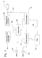
- FIG. 5 shows a circuit arrangement which makes possible a first possibility, namely an optical indication of the operating states of the UV tube 2.
- a first signal lamp 57 is connected to a first output of the switch 56.
- a second signal lamp 58 is connected to a second output of the switch 56.
- the first signal lamp 57 may be green in the present case and indicates the operating state of the UV tube 2 during which the instruments 4 are sterilized with the prescribed intensity of UV light.
- the second signal lamp 58 may be red in the present case and indicates that operating condition of the UV tube 2 during which the intensity of the emitted UV light is below the prescribed intensity.
- the aforementioned lamps 57 and 58 may be implemented as a single and per se known diode 95 (FIG. 3), which may be driven in two different ways. Depending on the type of control, this diode 95 may light up green or red.
- the diode 95 is mounted on the top of the carrier 20 and it is directed upwards. In the top wall 80 of the front cover 1, a corresponding opening 96 is executed. Through this opening 96, the diode 95 can be observed with which color it lights when switching between green and red. As long as the intensity of UV light below is the threshold level in the block "monitoring intensity" 54, burns the red lamp 58. After the intensity of the UV light has exceeded the threshold level, the green lamp burns 57th
- the green lamp 57 is connected to the first output of the changeover switch 56.
- a sleep switch 76 To the second output of the switch 56, one of the inputs of a sleep switch 76 is connected. A second input of the sleep switch 76 is connected via a control line 65 to the feed line 64 and thus also to the output of the device "control UV tube” 49.
- a first input of a breaker 77 is connected to the output of the red lamp 58 is connected.
- a timer 78 is connected to the output of the sleep switch 76, whose output is connected to a control input of the breaker 77.
- the supply of the UV tube 2 is broken off via the feed line 64 and it goes out.
- the level of the signal in the device "monitoring intensity" 54 drops below the threshold level provided, so that the switch 56 switches from the green lamp 57 to its second output, to which the first input of the sleep switch 76 is now connected instead of the red signal lamp 58 , Without this switch 76, the red signal lamp 58 would now continue to shine ununfierbrochen.
- the absence of the signal on the feed line 64 and thus also at the second input of the sleep switch 76 acts so that the sleep switch 76, the power of the red signal lamp 58th interrupts with energy and the red lamp 58 also goes out or does not start to light up.
- the failure of the UV tube 2 during operation, i. during a degermination process, is also recognized by the control electronics 10.
- the light sensor 44 no longer receives light from the UV tube 2.
- the intensity monitor 54 thus receives no signal from the light sensor 44, so that the level at the input of the intensity monitor 54 is below the said switching threshold.
- the intensity monitor 54 passes a corresponding signal to the switch 56, which causes the switch 56 to switch from the output "green light” 57 to its second output, namely, to the first input of the sleep switch 76.
- the voltage on the feed line 64 to the UV tube 2 remains in this case, however, because the voltage on the tube 2 is still applied. This is without regard to whether the tube 2 is defective or not. Consequently, this voltage is also at the second input of the sleep switch 76th
- the supply voltage is now at the second input of the sleep switch 76.
- the sleep switch 76 is designed to send a signal to a clock member 79 which causes the breaker 77 to supply the power to the red lamp 58 periodically interrupt.
- the flashing red light 58 signals the user of the device that the UV tube is defective and that it must be replaced.
- the red light 58 flashes until you pull the plug of the power supply unit 9 out of the device and thereby stops feeding the device.
- Fig. 6 shows a block diagram of a second embodiment for the signaling of the operating states of the present device.
- This block diagram is largely similar to the block diagram of Fig. 5.
- an acoustic signaling device 59 is connected to a (further) output of the sleep switch 56.
- This acoustic signaling device 59 may have a loudspeaker (not shown).
- the acoustic signaling can be done via a signal tone generator or a speech synthesizer with predetermined voice sequences.
- the same can also be equipped with a thermostat (not shown), which the UV light source switched on when exceeding a predetermined temperature, in particular in the interior of the housing 1.
- the connection of the thermostat is also designed so that this UV tube re-starts after the temperature sang below the threshold of danger.
- the device is characterized by a minimal power consumption and works in the safe for bathrooms low voltage range.
- This described device for germ-freeing and germ-free toothbrushes is not only intended for private households, but it can also be used in dental practices and hotel rooms. It is within the scope of the invention to use the device described or a similarly constructed device for germ-free and germ-free of other instruments that are used for the treatment or care of the human or animal body. In addition to medical or dental instruments, hairdressing instruments such as razors and the like as well as hand and foot care instruments may be considered. As a result, the UV radiation source switches on automatically during a movement process within the housing or the receptacle, whereby the sterilization is initiated.
- the control device is advantageously equipped with a counter which automatically switches off the switched-on UV light source after a predetermined time, for example after one hour.
Landscapes
- Health & Medical Sciences (AREA)
- Epidemiology (AREA)
- Life Sciences & Earth Sciences (AREA)
- Animal Behavior & Ethology (AREA)
- General Health & Medical Sciences (AREA)
- Public Health (AREA)
- Veterinary Medicine (AREA)
- Apparatus For Disinfection Or Sterilisation (AREA)
- Electrical Discharge Machining, Electrochemical Machining, And Combined Machining (AREA)
- Eye Examination Apparatus (AREA)
- Physical Water Treatments (AREA)
Claims (11)
- Appareil destiné à la stérilisation d'instruments (4), en particulier de brosses à dents (6), par rayonnement ultraviolet, qui peut être produit par une source de rayonnement (2), cet appareil étant conçu de telle sorte que le fonctionnement de la source de rayonnement (2) peut être surveillé, avec une partie intérieure (7) qui présente une paroi arrière longitudinale (85) sur laquelle la partie intérieure (7) peut être montée sur une paroi, et avec un boîtier (1) qui peut être affecté à la partie intérieure, caractérisé en ce que la partie intérieure (7) présente des faces (25), en ce que chacune de ces faces (25) se raccorde au bord extrême respectif de la paroi arrière longitudinale (85) de la partie intérieure et se trouve perpendiculaire au plan de cette paroi arrière (85), en ce que le boîtier (1) présente des parois latérales (81, 82) et est disposé sur ces parois latérales de façon orientable et verrouillable sur les faces de la paroi intérieure (7), en ce qu'un support longitudinal (20) est prévu pour la partie électronique (10) du présent appareil qui se trouve dans la partie intérieure (7), en ce que les sections finales (24) de ce support longitudinal (20) portent respectivement une prise (42, 43) pour la réception du connecteur d'un bloc de secteur (9), en ce que les parois latérales du boîtier (81, 82) sont munies respectivement d'une ouverture (40, 41) et en ce que ces ouvertures sont conçues de telle sorte que le connecteur d'une source à basse tension (9) passe à travers l'ouverture (40, 41) correspondante dans la paroi latérale du boîtier et peut être connecté dans la prise (42, 43) correspondante, lorsque le boîtier (1) se trouve à l'état fermé.
- Appareil selon la revendication 1, caractérisé en ce que les axes longitudinaux des prises (42, 43) pour la réception du connecteur de la source à basse tension (9) sont parallèles au plan du corps de base (21) du support (20), en ce que les prises (42, 43) s'ouvrent dans des directions opposées l'une à l'autre et plus précisément vers l'extérieur et en ce que chacune des ouvertures (40, 41) dans la paroi latérale du boîtier (81, 82) est alignée avec l'embouchure de réception d'une des prises (42, 43).
- Appareil selon la revendication 2, caractérisé en ce qu'une paroi de séparation (33) est prévue et se trouve à une certaine distance de la paroi arrière (85) de la partie intérieure (7), en ce que le support longitudinal (20) pour la partie électrique (10) est disposé dans une gaine de réception (35) qui se trouve entre la paroi arrière (85) de la partie intérieure (7) et la paroi de séparation (33), en ce que le support (20) porte une source de rayonnement longitudinale (2), en ce qu'une ouverture longitudinale (34) est réalisée dans la paroi de séparation (35) qui s'étend parallèlement à la source de rayonnement (2) et en ce qu'un dispositif de fixation (90) est prévu pour les instruments à traiter (4) et est attribué au côté opposé de la paroi de séparation (33).
- Appareil selon la revendication 3, caractérisé en ce que le corps de base (91) du dispositif de fixation (90) possède une section pour l'essentiel en forme de L, en ce que le dispositif (90) comprend en outre une coque longitudinale (94) ainsi qu'un peigne (17), en ce que la coque (94) se trouve sur la branche horizontale du L, en ce qu'un guidage en forme de fente (29) s'étend vers le haut depuis le fond de la coque (94), en ce que les parties de bordure (32) du peigne (17) opposées sont insérées dans le guidage respectif (29) et en ce que le peigne (17) présente des incisions (19) qui s'étendent verticalement depuis le haut et en ce que chaque incision respective (19) s'ouvre vers une des ouvertures (3) qui sont réalisées dans la paroi supérieure (80) du conteneur (1).
- Appareil selon la revendication 3, caractérisé en ce qu'un capteur (44) est associé à la source de rayonnement (2) et peut surveiller le fonctionnement de cette source de rayonnement (2), ledit capteur pouvant être un capteur de la lumière du jour, en ce qu'un dispositif (54) destiné à la mesure de l'intensité du rayonnement émis par la source de rayonnement (2) est raccordé à la sortie du capteur (44), en ce que des voyants (57, 58) et/ou un émetteur de signal acoustique (59) sont connectés aux sorties séparées du dispositif (54) pour mesurer l'intensité du rayonnement émis par la source de rayonnement (2) et en ce que la partie électrique (10) comprend une section qui sert à piloter la durée d'émission de la source de rayonnement (2).
- Appareil selon la revendication 5, caractérisé en ce qu'une ouverture (96) est réalisée dans la paroi supérieure (80) du boîtier (1) et en ce qu'au moins un des voyants (57, 58) se trouve sous cette ouverture (80) de sorte que l'état de celui-ci puisse être observé par l'ouverture (80).
- Appareil selon la revendication 5, caractérisé en ce que la partie électrique (10) présente un oscillateur (51) qui est connecté par un compteur (52) à une des entrées d'un comparateur (53), en ce qu'un dispositif (55) destiné à la détermination du temps de rayonnement de la source de rayonnement (2) est prévu, en ce que la sortie de ce dispositif de détermination (55) est connectée à une deuxième entrée du comparateur (53), en ce que la sortie du comparateur (53) est connectée à une deuxième entrée du dispositif de commande (49) et en ce qu'une deuxième sortie du détecteur d'instruments (16) est connectée à une deuxième entrée de commande du compteur (52).
- Appareil selon la revendication 7, caractérisé en ce qu'une deuxième sortie (68) du dispositif (54) destiné à contrôler l'intensité est connectée à une entrée de commande du dispositif (55) de détermination du temps de rayonnement.
- Appareil selon la revendication 7, caractérisé en ce qu'un détecteur (16) est prévu pour l'introduction des instruments (4) dans l'appareil, en ce que ce détecteur (16) est attribué au parcours des instruments (4) qui sont introduits dans le boîtier (1) et en ce que la sortie de ce détecteur (16) est connectée à un dispositif destiné à la commande (49) de la source de rayonnement (2).
- Appareil selon la revendication 5, caractérisé en ce que le capteur (16) est conçu comme une barrière lumineuse, en ce que cette barrière lumineuse comprend un émetteur de lumière (161) et un récepteur de lumière (162) entre lesquels se trouve une trajectoire de lumière (163), en ce que la source de lumière (161) et le récepteur de lumière (162) sont fixés sur des supports respectifs (23) qui se trouvent à une certaine distance l'un de l'autre et au-dessus de la platine (20) et en ce que la barrière lumineuse (16) est disposée au-dessus de chaque espace dans lequel se trouvent les têtes des instruments (4) introduits dans l'appareil pendant la stérilisation.
- Appareil selon la revendication 1, caractérisé en ce que deux montures (22) pour les parties extrêmes de la source de rayonnement longitudinale (2) sont fixées sur la face inférieure du corps de base (21) du support (20), en ce que ces montures (22) sont disposées de telle sorte que la source de rayonnement (2) se trouve à la hauteur de la tête (5) des instruments (4) qui sont introduits dans l'appareil.
Applications Claiming Priority (3)
| Application Number | Priority Date | Filing Date | Title |
|---|---|---|---|
| CH4042003 | 2003-03-12 | ||
| CH4042003 | 2003-03-12 | ||
| PCT/CH2004/000145 WO2004080495A1 (fr) | 2003-03-12 | 2004-03-11 | Dispositif destine au degermage d'instruments |
Publications (2)
| Publication Number | Publication Date |
|---|---|
| EP1601385A1 EP1601385A1 (fr) | 2005-12-07 |
| EP1601385B1 true EP1601385B1 (fr) | 2007-10-31 |
Family
ID=32968389
Family Applications (1)
| Application Number | Title | Priority Date | Filing Date |
|---|---|---|---|
| EP04719344A Expired - Lifetime EP1601385B1 (fr) | 2003-03-12 | 2004-03-11 | Dispositif destine au degermage d'instruments |
Country Status (4)
| Country | Link |
|---|---|
| EP (1) | EP1601385B1 (fr) |
| AT (1) | ATE376842T1 (fr) |
| DE (1) | DE502004005360D1 (fr) |
| WO (1) | WO2004080495A1 (fr) |
Families Citing this family (3)
| Publication number | Priority date | Publication date | Assignee | Title |
|---|---|---|---|---|
| US20130062534A1 (en) | 2010-05-10 | 2013-03-14 | Ted Cole | Uv germicidal system, method, and device thereof |
| US9974873B2 (en) | 2010-05-10 | 2018-05-22 | Uv Partners, Inc. | UV germicidal system, method, and device thereof |
| AU2021230386B2 (en) | 2020-03-06 | 2024-06-27 | Uv Partners, Inc. | UV disinfection platform |
Family Cites Families (4)
| Publication number | Priority date | Publication date | Assignee | Title |
|---|---|---|---|---|
| CH670568A5 (fr) * | 1988-08-24 | 1989-06-30 | Anton Ameseder | |
| US6592816B1 (en) * | 1999-03-01 | 2003-07-15 | Johnson & Johnson Vision Care, Inc. | Sterilization system |
| US6429438B1 (en) * | 1999-07-12 | 2002-08-06 | Waterhealth International, Inc. | Ultraviolet light detector for liquid disinfection unit |
| DE29915857U1 (de) * | 1999-09-09 | 2000-01-05 | Gerhards, Matthias, 87527 Sonthofen | Zahnbürstenhygieneschrank |
-
2004
- 2004-03-11 DE DE502004005360T patent/DE502004005360D1/de not_active Expired - Lifetime
- 2004-03-11 WO PCT/CH2004/000145 patent/WO2004080495A1/fr not_active Ceased
- 2004-03-11 EP EP04719344A patent/EP1601385B1/fr not_active Expired - Lifetime
- 2004-03-11 AT AT04719344T patent/ATE376842T1/de not_active IP Right Cessation
Also Published As
| Publication number | Publication date |
|---|---|
| ATE376842T1 (de) | 2007-11-15 |
| DE502004005360D1 (de) | 2007-12-13 |
| EP1601385A1 (fr) | 2005-12-07 |
| WO2004080495A1 (fr) | 2004-09-23 |
Similar Documents
| Publication | Publication Date | Title |
|---|---|---|
| EP0356896B1 (fr) | Dispositif pour la stérilisation d'instruments de toilette ou d'instruments médicaux | |
| DE68928731T2 (de) | Elektrotherapeutische einrichtung | |
| DE60112969T2 (de) | Uv pasteurisator | |
| DE69002999T2 (de) | Vorrichtung für die Zahnpflege. | |
| DE69708606T2 (de) | Verfahren und system zur verbesserung der handsauberkeit | |
| DE60316699T2 (de) | Dentalgerät zur untersuchung der zahnoberfläche | |
| DE69812036T2 (de) | Zahnärztliches Handgerät mit darin enthaltender Lichtquelle | |
| DE19618771A1 (de) | Wasserentnahmearmatur | |
| DE102012224183B4 (de) | Vorrichtung zur Emission von antimikrobieller Strahlung zur Anwendung auf menschlicher Haut | |
| EP0199158A2 (fr) | Brosse à dents | |
| DE4232487A1 (de) | Wurzelkanal-diagnose- und behandlungsgeraet | |
| DE3843047A1 (de) | Einrichtung zum regeln des zulaufes von wasser | |
| WO2019086598A1 (fr) | Dispositif de stockage et de désinfection de brosses de toilettes | |
| DE102017115743B4 (de) | Wasserdesinfektionsverfahren und Wasserzapfstellenanordnung dafür | |
| EP1601385B1 (fr) | Dispositif destine au degermage d'instruments | |
| DE60015328T3 (de) | Brausekopf mit einer ultraviolettlampe | |
| DE102011001094A1 (de) | Türgarnitur mit einer Einrichtung zur Desinfizierung | |
| DE202021100344U1 (de) | Schublade mit antiepidemischer Wirkung | |
| WO2000013565A1 (fr) | Toilettes | |
| DE3635568A1 (de) | Verfahren und geraet zur desinfektion und sterilisation des zufuehrungskreises der dynamischen instrumente fuer zahnaerzte | |
| EP0047418B1 (fr) | Lampe pour chambre noire | |
| DE3341797A1 (de) | Verfahren und vorrichtung zur entkeimung einer fluessigkeitsmenge, insbesondere einer wassermenge | |
| WO1999038806A1 (fr) | Dispositif pour steriliser l'eau qui traverse une installation sanitaire | |
| EP4062946A2 (fr) | Meuble doté d'un corps de meuble et d'une partie mobile de meuble | |
| EP1922950A1 (fr) | Appareil à tunnel destiné au durcissement de vernis à ongles |
Legal Events
| Date | Code | Title | Description |
|---|---|---|---|
| PUAI | Public reference made under article 153(3) epc to a published international application that has entered the european phase |
Free format text: ORIGINAL CODE: 0009012 |
|
| 17P | Request for examination filed |
Effective date: 20051011 |
|
| AK | Designated contracting states |
Kind code of ref document: A1 Designated state(s): AT BE BG CH CY CZ DE DK EE ES FI FR GB GR HU IE IT LI LU MC NL PL PT RO SE SI SK TR |
|
| AX | Request for extension of the european patent |
Extension state: AL LT LV MK |
|
| DAX | Request for extension of the european patent (deleted) | ||
| GRAP | Despatch of communication of intention to grant a patent |
Free format text: ORIGINAL CODE: EPIDOSNIGR1 |
|
| GRAS | Grant fee paid |
Free format text: ORIGINAL CODE: EPIDOSNIGR3 |
|
| GRAA | (expected) grant |
Free format text: ORIGINAL CODE: 0009210 |
|
| AK | Designated contracting states |
Kind code of ref document: B1 Designated state(s): AT BE BG CH CY CZ DE DK EE ES FI FR GB GR HU IE IT LI LU MC NL PL PT RO SE SI SK TR |
|
| REG | Reference to a national code |
Ref country code: GB Ref legal event code: FG4D Free format text: NOT ENGLISH |
|
| REG | Reference to a national code |
Ref country code: IE Ref legal event code: FG4D Free format text: LANGUAGE OF EP DOCUMENT: GERMAN |
|
| REG | Reference to a national code |
Ref country code: CH Ref legal event code: EP |
|
| REF | Corresponds to: |
Ref document number: 502004005360 Country of ref document: DE Date of ref document: 20071213 Kind code of ref document: P |
|
| NLV1 | Nl: lapsed or annulled due to failure to fulfill the requirements of art. 29p and 29m of the patents act | ||
| PG25 | Lapsed in a contracting state [announced via postgrant information from national office to epo] |
Ref country code: SE Free format text: LAPSE BECAUSE OF FAILURE TO SUBMIT A TRANSLATION OF THE DESCRIPTION OR TO PAY THE FEE WITHIN THE PRESCRIBED TIME-LIMIT Effective date: 20080131 Ref country code: ES Free format text: LAPSE BECAUSE OF FAILURE TO SUBMIT A TRANSLATION OF THE DESCRIPTION OR TO PAY THE FEE WITHIN THE PRESCRIBED TIME-LIMIT Effective date: 20080211 Ref country code: NL Free format text: LAPSE BECAUSE OF FAILURE TO SUBMIT A TRANSLATION OF THE DESCRIPTION OR TO PAY THE FEE WITHIN THE PRESCRIBED TIME-LIMIT Effective date: 20071031 |
|
| GBV | Gb: ep patent (uk) treated as always having been void in accordance with gb section 77(7)/1977 [no translation filed] | ||
| PG25 | Lapsed in a contracting state [announced via postgrant information from national office to epo] |
Ref country code: PL Free format text: LAPSE BECAUSE OF FAILURE TO SUBMIT A TRANSLATION OF THE DESCRIPTION OR TO PAY THE FEE WITHIN THE PRESCRIBED TIME-LIMIT Effective date: 20071031 Ref country code: SI Free format text: LAPSE BECAUSE OF FAILURE TO SUBMIT A TRANSLATION OF THE DESCRIPTION OR TO PAY THE FEE WITHIN THE PRESCRIBED TIME-LIMIT Effective date: 20071031 Ref country code: PT Free format text: LAPSE BECAUSE OF FAILURE TO SUBMIT A TRANSLATION OF THE DESCRIPTION OR TO PAY THE FEE WITHIN THE PRESCRIBED TIME-LIMIT Effective date: 20080331 Ref country code: BG Free format text: LAPSE BECAUSE OF FAILURE TO SUBMIT A TRANSLATION OF THE DESCRIPTION OR TO PAY THE FEE WITHIN THE PRESCRIBED TIME-LIMIT Effective date: 20080131 |
|
| REG | Reference to a national code |
Ref country code: IE Ref legal event code: FD4D |
|
| PG25 | Lapsed in a contracting state [announced via postgrant information from national office to epo] |
Ref country code: CZ Free format text: LAPSE BECAUSE OF FAILURE TO SUBMIT A TRANSLATION OF THE DESCRIPTION OR TO PAY THE FEE WITHIN THE PRESCRIBED TIME-LIMIT Effective date: 20071031 Ref country code: DK Free format text: LAPSE BECAUSE OF FAILURE TO SUBMIT A TRANSLATION OF THE DESCRIPTION OR TO PAY THE FEE WITHIN THE PRESCRIBED TIME-LIMIT Effective date: 20071031 |
|
| EN | Fr: translation not filed | ||
| PG25 | Lapsed in a contracting state [announced via postgrant information from national office to epo] |
Ref country code: RO Free format text: LAPSE BECAUSE OF FAILURE TO SUBMIT A TRANSLATION OF THE DESCRIPTION OR TO PAY THE FEE WITHIN THE PRESCRIBED TIME-LIMIT Effective date: 20071031 Ref country code: SK Free format text: LAPSE BECAUSE OF FAILURE TO SUBMIT A TRANSLATION OF THE DESCRIPTION OR TO PAY THE FEE WITHIN THE PRESCRIBED TIME-LIMIT Effective date: 20071031 |
|
| PLBE | No opposition filed within time limit |
Free format text: ORIGINAL CODE: 0009261 |
|
| STAA | Information on the status of an ep patent application or granted ep patent |
Free format text: STATUS: NO OPPOSITION FILED WITHIN TIME LIMIT |
|
| BERE | Be: lapsed |
Owner name: AMESEDER, ANTON Effective date: 20080331 |
|
| 26N | No opposition filed |
Effective date: 20080801 |
|
| PG25 | Lapsed in a contracting state [announced via postgrant information from national office to epo] |
Ref country code: MC Free format text: LAPSE BECAUSE OF NON-PAYMENT OF DUE FEES Effective date: 20080331 Ref country code: IE Free format text: LAPSE BECAUSE OF FAILURE TO SUBMIT A TRANSLATION OF THE DESCRIPTION OR TO PAY THE FEE WITHIN THE PRESCRIBED TIME-LIMIT Effective date: 20071031 Ref country code: FR Free format text: LAPSE BECAUSE OF FAILURE TO SUBMIT A TRANSLATION OF THE DESCRIPTION OR TO PAY THE FEE WITHIN THE PRESCRIBED TIME-LIMIT Effective date: 20080815 |
|
| REG | Reference to a national code |
Ref country code: CH Ref legal event code: NV Representative=s name: MOETTELI & ASSOCIES SARL Ref country code: CH Ref legal event code: PUE Owner name: CARMEN AMESEDER Free format text: AMESEDER, ANTON#LOEWENGARTENSTRASSE 11#CH-9400 RORSCHACH (CH) -TRANSFER TO- CARMEN AMESEDER#STEINWICHSLENSTRASSE 4#9052 NIEDERTEUFEN (CH) |
|
| PG25 | Lapsed in a contracting state [announced via postgrant information from national office to epo] |
Ref country code: GB Free format text: LAPSE BECAUSE OF FAILURE TO SUBMIT A TRANSLATION OF THE DESCRIPTION OR TO PAY THE FEE WITHIN THE PRESCRIBED TIME-LIMIT Effective date: 20071031 |
|
| PG25 | Lapsed in a contracting state [announced via postgrant information from national office to epo] |
Ref country code: GR Free format text: LAPSE BECAUSE OF FAILURE TO SUBMIT A TRANSLATION OF THE DESCRIPTION OR TO PAY THE FEE WITHIN THE PRESCRIBED TIME-LIMIT Effective date: 20080201 Ref country code: EE Free format text: LAPSE BECAUSE OF FAILURE TO SUBMIT A TRANSLATION OF THE DESCRIPTION OR TO PAY THE FEE WITHIN THE PRESCRIBED TIME-LIMIT Effective date: 20071031 |
|
| PG25 | Lapsed in a contracting state [announced via postgrant information from national office to epo] |
Ref country code: BE Free format text: LAPSE BECAUSE OF NON-PAYMENT OF DUE FEES Effective date: 20080331 Ref country code: FI Free format text: LAPSE BECAUSE OF FAILURE TO SUBMIT A TRANSLATION OF THE DESCRIPTION OR TO PAY THE FEE WITHIN THE PRESCRIBED TIME-LIMIT Effective date: 20071031 |
|
| PG25 | Lapsed in a contracting state [announced via postgrant information from national office to epo] |
Ref country code: CY Free format text: LAPSE BECAUSE OF FAILURE TO SUBMIT A TRANSLATION OF THE DESCRIPTION OR TO PAY THE FEE WITHIN THE PRESCRIBED TIME-LIMIT Effective date: 20071031 |
|
| PG25 | Lapsed in a contracting state [announced via postgrant information from national office to epo] |
Ref country code: LU Free format text: LAPSE BECAUSE OF NON-PAYMENT OF DUE FEES Effective date: 20080311 Ref country code: HU Free format text: LAPSE BECAUSE OF FAILURE TO SUBMIT A TRANSLATION OF THE DESCRIPTION OR TO PAY THE FEE WITHIN THE PRESCRIBED TIME-LIMIT Effective date: 20080501 |
|
| PG25 | Lapsed in a contracting state [announced via postgrant information from national office to epo] |
Ref country code: TR Free format text: LAPSE BECAUSE OF FAILURE TO SUBMIT A TRANSLATION OF THE DESCRIPTION OR TO PAY THE FEE WITHIN THE PRESCRIBED TIME-LIMIT Effective date: 20071031 |
|
| PGFP | Annual fee paid to national office [announced via postgrant information from national office to epo] |
Ref country code: CH Payment date: 20100917 Year of fee payment: 7 |
|
| PGFP | Annual fee paid to national office [announced via postgrant information from national office to epo] |
Ref country code: AT Payment date: 20100827 Year of fee payment: 7 Ref country code: DE Payment date: 20100902 Year of fee payment: 7 |
|
| PG25 | Lapsed in a contracting state [announced via postgrant information from national office to epo] |
Ref country code: IT Free format text: LAPSE BECAUSE OF NON-PAYMENT OF DUE FEES Effective date: 20080331 |
|
| REG | Reference to a national code |
Ref country code: CH Ref legal event code: PL |
|
| PG25 | Lapsed in a contracting state [announced via postgrant information from national office to epo] |
Ref country code: AT Free format text: LAPSE BECAUSE OF NON-PAYMENT OF DUE FEES Effective date: 20110311 |
|
| PG25 | Lapsed in a contracting state [announced via postgrant information from national office to epo] |
Ref country code: CH Free format text: LAPSE BECAUSE OF NON-PAYMENT OF DUE FEES Effective date: 20110331 Ref country code: DE Free format text: LAPSE BECAUSE OF NON-PAYMENT OF DUE FEES Effective date: 20111001 Ref country code: LI Free format text: LAPSE BECAUSE OF NON-PAYMENT OF DUE FEES Effective date: 20110331 |
|
| REG | Reference to a national code |
Ref country code: DE Ref legal event code: R119 Ref document number: 502004005360 Country of ref document: DE Effective date: 20111001 |