EP1601439B1 - Verfahren und vorrichtung zum filtern von abgasteilchen - Google Patents
Verfahren und vorrichtung zum filtern von abgasteilchen Download PDFInfo
- Publication number
- EP1601439B1 EP1601439B1 EP04715700A EP04715700A EP1601439B1 EP 1601439 B1 EP1601439 B1 EP 1601439B1 EP 04715700 A EP04715700 A EP 04715700A EP 04715700 A EP04715700 A EP 04715700A EP 1601439 B1 EP1601439 B1 EP 1601439B1
- Authority
- EP
- European Patent Office
- Prior art keywords
- plate
- exhaust flow
- plates
- exhaust
- micropockets
- Prior art date
- Legal status (The legal status is an assumption and is not a legal conclusion. Google has not performed a legal analysis and makes no representation as to the accuracy of the status listed.)
- Expired - Lifetime
Links
Images


Classifications
-
- F—MECHANICAL ENGINEERING; LIGHTING; HEATING; WEAPONS; BLASTING
- F01—MACHINES OR ENGINES IN GENERAL; ENGINE PLANTS IN GENERAL; STEAM ENGINES
- F01N—GAS-FLOW SILENCERS OR EXHAUST APPARATUS FOR MACHINES OR ENGINES IN GENERAL; GAS-FLOW SILENCERS OR EXHAUST APPARATUS FOR INTERNAL-COMBUSTION ENGINES
- F01N3/00—Exhaust or silencing apparatus having means for purifying, rendering innocuous, or otherwise treating exhaust
- F01N3/02—Exhaust or silencing apparatus having means for purifying, rendering innocuous, or otherwise treating exhaust for cooling, or for removing solid constituents of, exhaust
- F01N3/021—Exhaust or silencing apparatus having means for purifying, rendering innocuous, or otherwise treating exhaust for cooling, or for removing solid constituents of, exhaust by means of filters
- F01N3/022—Exhaust or silencing apparatus having means for purifying, rendering innocuous, or otherwise treating exhaust for cooling, or for removing solid constituents of, exhaust by means of filters characterised by specially adapted filtering structure, e.g. honeycomb, mesh or fibrous
-
- B—PERFORMING OPERATIONS; TRANSPORTING
- B01—PHYSICAL OR CHEMICAL PROCESSES OR APPARATUS IN GENERAL
- B01D—SEPARATION
- B01D46/00—Filters or filtering processes specially modified for separating dispersed particles from gases or vapours
- B01D46/10—Particle separators, e.g. dust precipitators, using filter plates, sheets or pads having plane surfaces
-
- B—PERFORMING OPERATIONS; TRANSPORTING
- B01—PHYSICAL OR CHEMICAL PROCESSES OR APPARATUS IN GENERAL
- B01D—SEPARATION
- B01D46/00—Filters or filtering processes specially modified for separating dispersed particles from gases or vapours
- B01D46/56—Filters or filtering processes specially modified for separating dispersed particles from gases or vapours with multiple filtering elements, characterised by their mutual disposition
- B01D46/62—Filters or filtering processes specially modified for separating dispersed particles from gases or vapours with multiple filtering elements, characterised by their mutual disposition connected in series
- B01D46/64—Filters or filtering processes specially modified for separating dispersed particles from gases or vapours with multiple filtering elements, characterised by their mutual disposition connected in series arranged concentrically or coaxially
-
- F—MECHANICAL ENGINEERING; LIGHTING; HEATING; WEAPONS; BLASTING
- F01—MACHINES OR ENGINES IN GENERAL; ENGINE PLANTS IN GENERAL; STEAM ENGINES
- F01N—GAS-FLOW SILENCERS OR EXHAUST APPARATUS FOR MACHINES OR ENGINES IN GENERAL; GAS-FLOW SILENCERS OR EXHAUST APPARATUS FOR INTERNAL-COMBUSTION ENGINES
- F01N3/00—Exhaust or silencing apparatus having means for purifying, rendering innocuous, or otherwise treating exhaust
- F01N3/02—Exhaust or silencing apparatus having means for purifying, rendering innocuous, or otherwise treating exhaust for cooling, or for removing solid constituents of, exhaust
- F01N3/021—Exhaust or silencing apparatus having means for purifying, rendering innocuous, or otherwise treating exhaust for cooling, or for removing solid constituents of, exhaust by means of filters
- F01N3/0215—Exhaust or silencing apparatus having means for purifying, rendering innocuous, or otherwise treating exhaust for cooling, or for removing solid constituents of, exhaust by means of filters the filtering elements having the form of disks or plates
-
- F—MECHANICAL ENGINEERING; LIGHTING; HEATING; WEAPONS; BLASTING
- F01—MACHINES OR ENGINES IN GENERAL; ENGINE PLANTS IN GENERAL; STEAM ENGINES
- F01N—GAS-FLOW SILENCERS OR EXHAUST APPARATUS FOR MACHINES OR ENGINES IN GENERAL; GAS-FLOW SILENCERS OR EXHAUST APPARATUS FOR INTERNAL-COMBUSTION ENGINES
- F01N3/00—Exhaust or silencing apparatus having means for purifying, rendering innocuous, or otherwise treating exhaust
- F01N3/02—Exhaust or silencing apparatus having means for purifying, rendering innocuous, or otherwise treating exhaust for cooling, or for removing solid constituents of, exhaust
- F01N3/021—Exhaust or silencing apparatus having means for purifying, rendering innocuous, or otherwise treating exhaust for cooling, or for removing solid constituents of, exhaust by means of filters
- F01N3/033—Exhaust or silencing apparatus having means for purifying, rendering innocuous, or otherwise treating exhaust for cooling, or for removing solid constituents of, exhaust by means of filters in combination with other devices
- F01N3/035—Exhaust or silencing apparatus having means for purifying, rendering innocuous, or otherwise treating exhaust for cooling, or for removing solid constituents of, exhaust by means of filters in combination with other devices with catalytic reactors
-
- B—PERFORMING OPERATIONS; TRANSPORTING
- B01—PHYSICAL OR CHEMICAL PROCESSES OR APPARATUS IN GENERAL
- B01D—SEPARATION
- B01D2275/00—Filter media structures for filters specially adapted for separating dispersed particles from gases or vapours
- B01D2275/30—Porosity of filtering material
-
- B—PERFORMING OPERATIONS; TRANSPORTING
- B01—PHYSICAL OR CHEMICAL PROCESSES OR APPARATUS IN GENERAL
- B01D—SEPARATION
- B01D2279/00—Filters adapted for separating dispersed particles from gases or vapours specially modified for specific uses
- B01D2279/30—Filters adapted for separating dispersed particles from gases or vapours specially modified for specific uses for treatment of exhaust gases from IC Engines
-
- F—MECHANICAL ENGINEERING; LIGHTING; HEATING; WEAPONS; BLASTING
- F01—MACHINES OR ENGINES IN GENERAL; ENGINE PLANTS IN GENERAL; STEAM ENGINES
- F01N—GAS-FLOW SILENCERS OR EXHAUST APPARATUS FOR MACHINES OR ENGINES IN GENERAL; GAS-FLOW SILENCERS OR EXHAUST APPARATUS FOR INTERNAL-COMBUSTION ENGINES
- F01N2330/00—Structure of catalyst support or particle filter
- F01N2330/02—Metallic plates or honeycombs, e.g. superposed or rolled-up corrugated or otherwise deformed sheet metal
-
- F—MECHANICAL ENGINEERING; LIGHTING; HEATING; WEAPONS; BLASTING
- F02—COMBUSTION ENGINES; HOT-GAS OR COMBUSTION-PRODUCT ENGINE PLANTS
- F02B—INTERNAL-COMBUSTION PISTON ENGINES; COMBUSTION ENGINES IN GENERAL
- F02B37/00—Engines characterised by provision of pumps driven at least for part of the time by exhaust
-
- Y—GENERAL TAGGING OF NEW TECHNOLOGICAL DEVELOPMENTS; GENERAL TAGGING OF CROSS-SECTIONAL TECHNOLOGIES SPANNING OVER SEVERAL SECTIONS OF THE IPC; TECHNICAL SUBJECTS COVERED BY FORMER USPC CROSS-REFERENCE ART COLLECTIONS [XRACs] AND DIGESTS
- Y10—TECHNICAL SUBJECTS COVERED BY FORMER USPC
- Y10S—TECHNICAL SUBJECTS COVERED BY FORMER USPC CROSS-REFERENCE ART COLLECTIONS [XRACs] AND DIGESTS
- Y10S55/00—Gas separation
- Y10S55/30—Exhaust treatment
-
- Y—GENERAL TAGGING OF NEW TECHNOLOGICAL DEVELOPMENTS; GENERAL TAGGING OF CROSS-SECTIONAL TECHNOLOGIES SPANNING OVER SEVERAL SECTIONS OF THE IPC; TECHNICAL SUBJECTS COVERED BY FORMER USPC CROSS-REFERENCE ART COLLECTIONS [XRACs] AND DIGESTS
- Y10—TECHNICAL SUBJECTS COVERED BY FORMER USPC
- Y10T—TECHNICAL SUBJECTS COVERED BY FORMER US CLASSIFICATION
- Y10T428/00—Stock material or miscellaneous articles
- Y10T428/24—Structurally defined web or sheet [e.g., overall dimension, etc.]
- Y10T428/24628—Nonplanar uniform thickness material
- Y10T428/24669—Aligned or parallel nonplanarities
Definitions
- the present disclosure relates generally to an exhaust system, and particularly to a particulate filter for an exhaust system.
- Automotive exhaust systems for diesel and other internal combustion engines typically include an exhaust subsystem that limits the mass of particulate matter emitted with the exhaust gases.
- this matter typically includes both carbonaceous components and metallic components.
- Present filtering methods to trap the exhaust particulates include both surface filtration and depth filtration approaches.
- Surface filtration relies on interception as the mechanism for particulate filtration, while depth filtration relies on impaction as the main mechanism for particulate filtration.
- surface filtration systems particulate deposits tend to block the flow path and lead to high trapping efficiency and an increase in pressure drop over time.
- depth filtration systems particulate deposits do not block the flow path, which leads to low trapping efficiency and limited change in pressure drop over time.
- EP 0 353 679 A1 describes a filter apparatus which is designed for filtering solid, liquid or gaseous, electrically uncharged or electrically charged particles out of a gaseous flow medium as it flows through the filter apparatus.
- the filter apparatus has a housing and filter elements arranged in the housing.
- the filter elements are arranged parallel to each other and spaced from each other in the direction of flow of the gaseous medium to the apparatus.
- Each filter element has a plate-like carrier element and a substrate which are provided with spaced-apart openings.
- the substrate serves for the storage of a filter medium.
- Each opening in the filter element has a sleeve-like guide element for the flow medium, wherein the guide element extends around the edge of the corresponding opening.
- the guide elements which project at least at the upstream side prevent filter medium at the individual substrates from being unintentionally entrained through the openings, even at high flow rates in respect of the flow medium.
- a particulate filter for an exhaust system having an exhaust flow and a nominal flow area includes a housing and a plurality of plates arranged parallel to each other within the housing, each plate having a plurality of orifices and a plurality of micropockets configured to trap exhaust particulates.
- a particulate filter for an exhaust system having an exhaust flow and a nominal flow area includes a housing and a plurality of plates, each plate having a plurality of orifices and a plurality of micropockets arranged within the housing and configured to trap exhaust particulates.
- the plates are arranged parallel to each other as plate pairs and have their micropockets facing the exhaust flow.
- the plates have gaps between them that decrease in size in the direction of the exhaust flow.
- the orifices of each plate are in line with the micropockets of an adjacent plate, each orifice being surrounded by a funnel shaped surface with the bottom of the funnel facing the exhaust flow.
- the total flow through area of the orifices of each plate is equal to or greater than the nominal flow area of the exhaust system.
- a method for filtering particulates of an exhaust flow of an exhaust system includes receiving the exhaust flow at one end of a particulate filter, impinging the exhaust flow on the plates, collecting a portion of the particulates at micropockets on the plates, passing a portion of the exhaust flow through orifices on the plates toward a subsequent plate, repeating the impinging, collecting, and passing processes for all plates, and discharging the exhaust flow at an opposite end of the particulate filter.
- the plates are arranged perpendicular to the exhaust flow and have gaps between them.
- the orifices of each plate are in line with the micropockets of a subsequent plate.
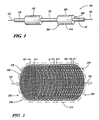
- Fig. 1 depicts an exhaust system employing an embodiment of the invention
- Fig. 2 depicts an isometric view of a particulate filter in accordance with an embodiment of the invention
- Fig. 3 depicts a cross section side view of an arrangement of filter plates employed in the particulate filter of Figure 2 ;
- Fig. 4 depicts an enlarged front view of a portion of the filter plate depicted in Figures 2 and 3 ;
- Fig. 5 depicts an enlarged side view of a portion of the filter plate depicted in Figure 3 ;
- Fig. 6 depicts a cross section side view of another arrangement of filter plates in accordance with an embodiment of the invention.
- Fig. 7 depicts an enlarged illustrative view of filtration efficiency as a function of micropocket shape and flow rate
- Fig. 8 depicts an alternative front view of the filter plate arrangement depicted in Figure 4 .
- An embodiment of the invention provides a particulate filter for an exhaust system of an automotive diesel engine. While the embodiment described herein depicts an automotive diesel engine as an exemplary diesel powerplant using a particulate filter, it will be appreciated that the disclosed invention is also applicable to other diesel powerplants that require the functionality of a particulate filter herein disclosed, such as a diesel powered generator for example. While the disclosed invention is well suited for filtering the combustion byproducts of a diesel engine, it may also be applicable for filtering combustion byproducts of a gasoline powered engine.
- An exemplary exhaust system 100 for an automotive diesel engine is depicted in Figure 1 having manifold exhaust pipes 110 suitably connected at one end to exhaust manifolds (not shown) of the diesel engine (not shown) for receiving an exhaust flow, depicted generally as numeral 150, intermediate exhaust pipes 120, a turbocharger exhaust pipe 130 coupled to a tailpipe (not shown) for exhausting the conditioned exhaust flow to atmosphere, a turbocharger 140 suitably connected between intermediate exhaust pipes 120 and turbocharger exhaust pipe 130, and particulate filters 200 suitably connected intermediate manifold exhaust pipes 110 and intermediate exhaust pipes 120 for trapping exhaust particulates present in the exhaust flow 150.
- Exhaust flow 150 passes from exhaust manifolds (not shown) to manifold exhaust pipes 110, particulate filters 200, intermediate exhaust pipes 120, turbocharger 140, turbocharger exhaust pipe 130, and then to atmosphere.
- Exhaust system 100 has a nominal flow area equal to or greater than the inside cross-sectional flow area of manifold exhaust pipes 110.
- particulate filter 200 is arranged in a pre-turbo, as opposed to a post-turbo, location. Since the exhaust gas temperature is higher at a pre-turbo location (versus post-turbo), regeneration of particulate filter 200 may benefit by positioning particulate filter 200 at the pre-turbo location. However, as a filtering device, particulate filter 200 may be positioned at either a pre- or a post-turbo location.
- Each particulate filter 200 has a housing 210, which may be any form of construction and configuration suitable for the purpose, and a plurality of plates 220 arranged parallel to each other and retained within housing 210 by any means suitable for the purpose, the plurality of plates 220 composing a filter element for trapping exhaust particulates, as best seen by now referring to Figure 2 .
- Each plate 225 has a plurality of orifices 230 and a plurality of micropockets 240, best seen by referring to Figure 3 , which depicts plates 220 in cross-sectional side view through orifices 230 and micropockets 240.
- FIG. 4 An enlarged front view of a portion of plate 225 is depicted in Figure 4 showing orifices 230 and micropockets 240 as small and large discs, respectively, and arranged intermediate each other.
- Figure 8 depicts an alternative arrangement to the plate 225 of Figure 4 , where orifices 230 are depicted as small discs, funnel shaped surfaces 235 (discussed in reference to Figure 3 below) surrounding orifices 230 are depicted as larger concentric discs, and micropockets 240 are depicted as the regions between the funnel shaped surfaces 235.
- An embodiment of particulate filter 200 includes an arrangement of orifices 230 where the total flow through area of orifices 230 on each plate 220 is equal to or greater than the nominal flow area of exhaust system 100, thereby preventing excessive pressure drop within exhaust system 100.
- each plate 225 is formed by known forming means to create crescent shaped micropockets 240 with orifices 230 therebetween and a funnel shaped surface 235 around each orifice 230.
- Funnel shaped surface 235 may be fabricated, for example, by a die extrusion process.
- An embodiment of particulate filter 200 has the bottoms of each funnel shaped surface (funnel) 235 facing the exhaust flow 150.
- the term facing the exhaust flow as used herein refers to the orientation of a part that faces the direction from which the exhaust flow is locally traveling.
- micropockets 240 facing the exhaust flow 150 (as seen in Figure 3 ), that is, the internal crescent shaped surfaces of micropockets 240 face the exhaust flow 150.
- orifices 230 and micropockets 240 on successive plates 220 is such that the orifices 230 of a preceding plate, a first plate 226, are arranged in line with micropockets 240 of a succeeding plate, a second plate 227, as best seen by referring to Figures 3 and 5 , where Figure 5 depicts an enlarged side view of a portion of Figure 3 showing the exhaust flow 150 through orifices 230 of successive plates 220.
- the exhaust flow 150 through orifices 230 of first plate 226 is directed toward the centers of micropockets 240 of second plate 227, and the exhaust flow 150 through orifices 230 of second plate 227 is directed toward the centers of micropockets 240 of third plate 228.
- the crescent shaped micropockets 240 and the offset arrangement of orifices 230 and micropockets 240 from one plate 220 to the next results in exhaust particulates being trapped in micropockets 240 and the passing of a less contaminated flow to the next plate 220.
- the term in line with as used herein not only refers to an arrangement of orifices 230 of first plate 226 that aim the exhaust flow 150 directly at the center of micropockets 240 of second plate 227, but rather refers to the general flow from one plate 220 to the next where the exhaust flow 150 is directed toward the micropockets in the successive plate for the purpose of trapping exhaust particulates.
- an embodiment of particulate filter 200 has an arrangement of plates 220 where the gap G1 between the first two successive plates 220 is greater that the gap G2 between the last two successive plates 220 and where the gap g between each successive plate 220 decreases in dimension in the direction of exhaust flow 150.
- exhaust flow 150 travels through particulate filter 200, it is natural for larger particulates to be trapped in the micropockets 240 at the front of particulate filter 200 first, and for smaller particulates to travel further through particulate filter 200.
- gap g between each successive plate 220 By arranging gap g between each successive plate 220 to decrease in the direction of exhaust flow 150, the smaller particulates can be trapped at the end of particulate filter 200.
- FIG. 6 Another embodiment of particulate filter 200 is depicted in Figure 6 , which shows an arrangement of plates 220 that alternate in direction to produce an arrangement of plate pairs 245 having a first plate 246 and a second plate 247.
- micropockets 240 of first plate 246 face opposite to the direction of exhaust flow 150 and micropockets 240 of second plate 247 face the direction of exhaust flow 150, and orifices 230 of first plate 246 are arranged in line with micropockets 240 of second plate 247.
- This arrangement of plate pairs 245 continues for the balance of plates 220 in the particulate filter 200 of Figure 6 .
- gap h refers to the distance between the bottom of funnels 235 of first plate 246 and the bottom of micropockets 240 of second plate 247.
- gap H1 in the first plate pair 245 is greater than gap H2 in the last plate pair 245.
- the embodiment depicted in Figure 6 provides for a greater packing density of plates 220, thereby resulting in more exhaust filtration per increment of exhaust flow.
- the exhaust particulate filtering method begins with particulate filter 200 receiving exhaust flow 150 at one end 202 of particulate filter 200, where exhaust flow 150 then impinges on a plate 225 of a plurality of plates 220, each plate 220 having a plurality of orifices 230 and a plurality of micropockets 240.
- Plates 220 are arranged perpendicular to the exhaust flow 150, that is, facing the exhaust flow, and have gaps g separating them.
- separation gaps g decrease in magnitude in the direction of exhaust flow 150, thereby enabling small particulate filtration, and each micropocket 240 of each plate 220 faces the direction of exhaust flow 150.
- orifices 230 are arranged as funnels with funnel shaped surfaces 235, and the bottom of each funnel of each plate 220 is arranged to face the flow stream of exhaust flow 150.
- the exhaust particulate filtering method involves the impinging of exhaust flow 150 on plates 220 where micropockets 240 of each other plate are arranged to face the flow stream of exhaust flow 150.
- orifices 230 are arranged as funnels having a funnel shaped surface 235 where the bottoms of each funnel of each other plate 220 face the flow stream of exhaust flow 150.
- plates 220 are arranged perpendicular to the exhaust flow 150 with separation gaps h therebetween that decrease in magnitude in the direction of exhaust flow 150, thereby enabling small particulate filtration.
- the bottoms of the funnels of orifices 230 of each other plate 220 direct exhaust flow 150 toward micropockets 240 of each subsequent plate 220.
- plates 220 are fabricated from a known metallic substrate composition having iron, chromium, aluminum, and yttrium, which is then coated with a catalyst such as platinum.
- the catalyzed particulate trap can facilitate low temperature oxidation of carbonaceous components in the deposited particulates.
- the metallic components in the particulate deposits (known as ash) cannot be burned.
- Orifices 230 and gaps g and h are sized to allow the passage of ash particles, which are small in size compared to the deposited particulates. In an embodiment, orifices 230 are about .05 centimeters in diameter, and gaps g and h are about. 01 centimeters to about .1 centimeters in dimension.
- Figure 7 depicts several shapes that may be employed for micropockets 240, including round 250, rectangle 260, and crescent 270.
- the estimated filtration efficiency is represented by shaded regions 255, 265, 275 for each shape 250, 260, 270, respectively.
Landscapes
- Engineering & Computer Science (AREA)
- Chemical & Material Sciences (AREA)
- Chemical Kinetics & Catalysis (AREA)
- Combustion & Propulsion (AREA)
- Mechanical Engineering (AREA)
- General Engineering & Computer Science (AREA)
- Processes For Solid Components From Exhaust (AREA)
- Filtering Of Dispersed Particles In Gases (AREA)
- Exhaust Gas After Treatment (AREA)
Claims (12)
- Partikelfilter (200) für eine Abgasanlage (100), der eine Abgasströmung (150) sowie eine Nennströmungsfläche aufweist, umfassend:ein Gehäuse (210); undeine Vielzahl von Platten (220), die rechtwinklig zu der Abgasströmung und parallel zueinander in dem Gehäuse (210) angeordnet sind, wobei jede der Vielzahl von Platten (220) eine Vielzahl von Öffnungen (230) und eine Vielzahl von Mikrotaschen (240) aufweist, die derart ausgestaltet sind, um Abgaspartikel abzufangen,wobei die Vielzahl von Platten (220) eine Vielzahl von Spalten (g, h) dazwischen definiert, wobei die Vielzahl von Spalten (g, h) derart ausgestaltet ist, dass sie in der Richtung der Abgasströmung (150) eine abnehmende Abmessung besitzt.
- Partikelfilter nach Anspruch 1, wobei die Vielzahl von Öffnungen (230) und die Vielzahl von Mikrotaschen (240) von jeder der Vielzahl von Platten (220) zwischen einander angeordnet sind.
- Partikelfilter nach Anspruch 2, wobei die Vielzahl von Öffnungen (230) durch eine trichterförmige Fläche (235) umgeben ist, wobei die Böden jedes Trichters (235) von zumindest einer Platte der Vielzahl von Platten (220) zu der Abgasströmung (150) weisen.
- Partikelfilter nach Anspruch 1, wobei die Vielzahl von Platten (220) eine erste und zweite Platte (226, 227) umfasst, die jeweils die Vielzahl von zu der Abgasströmung (150) weisenden Mikrotaschen (240) aufweisen, wobei die Vielzahl von Öffnungen (230) der ersten Platte (226) mit der Vielzahl von Mikrotaschen (240) der zweiten Platte (227) ausgerichtet ist.
- Partikelfilter nach Anspruch 1, wobei die Gesamtströmung durch die Fläche der Vielzahl von Öffnungen (230) von jeder der Vielzahl von Platten (220) gleich oder größer als die Nennströmungsfläche der Abgasanlage (100) ist.
- Partikelfilter nach Anspruch 1, wobei die Vielzahl von Platten (220) eine Vielzahl von Plattenpaaren (245) umfasst, die eine erste Platte (246), deren Vielzahl von Mikrotaschen (240) entgegengesetzt zu der Abgasströmung (150) weist, und eine benachbarte zweite Platte (247) aufweist, deren Vielzahl von Mikrotaschen (240) zu der Abgasströmung (150) weist, wobei die Vielzahl von Öffnungen (230) der ersten Platte (246) mit der Vielzahl von Mikrotaschen (240) der zweiten Platte (247) ausgerichtet ist.
- Verfahren zum Filtern von Partikeln einer Abgasströmung (150) einer Abgasanlage (100), umfassend, dass:die Abgasströmung (150) an einem Ende eines Partikelfilters (200) aufgenommen wird;die Abgasströmung (150) auf eine Platte einer Vielzahl von Platten (220) auftreffen gelassen wird, die jeweils eine Vielzahl von Öffnungen (230) und eine Vielzahl von Mikrotaschen (240) aufweisen, wobei die Vielzahl von Platten (220) rechtwinklig zu der Abgasströmung (150) mit Spalten (g, h) dazwischen angeordnet ist, deren Größe in der Richtung der Abgasströmung (150) abnimmt;ein Anteil der Partikel an der Vielzahl von Mikrotaschen (240) der Platte gesammelt wird;ein Anteil der Abgasströmung (150) durch die Vielzahl von Öffnungen (230) der Platte in Richtung einer nachfolgenden Platte geführt wird;das Auftreffenlassen der Abgasströmung (150), das Sammeln eines Anteils der Partikel und das Führen eines Anteils der Abgasströmung (150) für die Vielzahl von Platten (220) wiederholt werden; unddie Abgasströmung (150) an einem gegenüberliegenden Ende des Partikelfilters (200) ausgetragen wird.
- Verfahren nach Anspruch 7, wobei das Auftreffenlassen der Abgasströmung ferner umfasst, dass die Abgasströmung auf eine Platte einer Vielzahl von Platten auftreffen gelassen wird, wobei die Vielzahl von Mikrotaschen jeder Platte derart ausgebildet ist, um zu dem Durchflussstrom der Abgasströmung zu weisen.
- Verfahren nach Anspruch 7, wobei das Auftreffenlassen der Abgasströmung (150) ferner umfasst, dass die Abgasströmung (150) auf eine Platte einer Vielzahl von Platten (220) auftreffen gelassen wird, wobei die Vielzahl von Öffnungen (230) als Trichter (235) angeordnet ist, wobei der Boden jedes Trichters (235) von jeder der Vielzahl von Platten (220) zu dem Durchflussstrom der Abgasströmung (150) weist.
- Verfahren nach Anspruch 7, wobei das Auftreffenlassen der Abgasströmung (150) ferner umfasst, dass die Abgasströmung (150) auf eine Platte einer Vielzahl von Platten (220) auftreffen gelassen wird, wobei die Vielzahl von Mikrotaschen (240) jeder weiteren Platte derart ausgebildet ist, um zu dem Durchflussstrom der Abgasströmung (150) zu weisen.
- Verfahren nach Anspruch 10, wobei das Auftreffenlassen der Abgasströmung (150) ferner umfasst, dass die Abgasströmung (150) auf eine Platte einer Vielzahl von Platten (220) auftreffen gelassen wird, wobei die Vielzahl von Öffnungen (230) als Trichter (235) angeordnet ist, wobei der Boden jedes Trichters (235) jeder weiteren Platte zu dem Durchflussstrom der Abgasströmung (150) weist.
- Verfahren nach Anspruch 7, wobei die Vielzahl von Öffnungen (230) der Platte mit den Mikrotaschen (240) der nachfolgenden Platte ausgerichtet ist.
Applications Claiming Priority (3)
| Application Number | Priority Date | Filing Date | Title |
|---|---|---|---|
| US378270 | 2003-03-03 | ||
| US10/378,270 US6764532B1 (en) | 2003-03-03 | 2003-03-03 | Method and apparatus for filtering exhaust particulates |
| PCT/US2004/005987 WO2004078319A1 (en) | 2003-03-03 | 2004-02-27 | Method and apparatus for filtering exhaust particulates |
Publications (3)
| Publication Number | Publication Date |
|---|---|
| EP1601439A1 EP1601439A1 (de) | 2005-12-07 |
| EP1601439A4 EP1601439A4 (de) | 2007-05-09 |
| EP1601439B1 true EP1601439B1 (de) | 2010-04-07 |
Family
ID=32681784
Family Applications (1)
| Application Number | Title | Priority Date | Filing Date |
|---|---|---|---|
| EP04715700A Expired - Lifetime EP1601439B1 (de) | 2003-03-03 | 2004-02-27 | Verfahren und vorrichtung zum filtern von abgasteilchen |
Country Status (5)
| Country | Link |
|---|---|
| US (1) | US6764532B1 (de) |
| EP (1) | EP1601439B1 (de) |
| CN (1) | CN100361728C (de) |
| DE (1) | DE602004026421D1 (de) |
| WO (1) | WO2004078319A1 (de) |
Families Citing this family (10)
| Publication number | Priority date | Publication date | Assignee | Title |
|---|---|---|---|---|
| DE102006003317B4 (de) | 2006-01-23 | 2008-10-02 | Alstom Technology Ltd. | Rohrbündel-Wärmetauscher |
| US9557119B2 (en) | 2009-05-08 | 2017-01-31 | Arvos Inc. | Heat transfer sheet for rotary regenerative heat exchanger |
| US8622115B2 (en) * | 2009-08-19 | 2014-01-07 | Alstom Technology Ltd | Heat transfer element for a rotary regenerative heat exchanger |
| US9200853B2 (en) | 2012-08-23 | 2015-12-01 | Arvos Technology Limited | Heat transfer assembly for rotary regenerative preheater |
| US10175006B2 (en) | 2013-11-25 | 2019-01-08 | Arvos Ljungstrom Llc | Heat transfer elements for a closed channel rotary regenerative air preheater |
| CN104949212B (zh) * | 2014-03-28 | 2017-11-14 | Lg电子株式会社 | 空气净化器 |
| CN104949213B (zh) | 2014-03-28 | 2017-09-29 | Lg电子株式会社 | 空气净化器 |
| US10927457B2 (en) * | 2015-03-04 | 2021-02-23 | Toshiba Memory Corporation | Semiconductor manufacturing apparatus |
| US10094626B2 (en) | 2015-10-07 | 2018-10-09 | Arvos Ljungstrom Llc | Alternating notch configuration for spacing heat transfer sheets |
| DE102017124225A1 (de) * | 2017-10-18 | 2019-04-18 | Man Diesel & Turbo Se | Abgasnachbehandlungssystem und Verfahren zur Abgasnachbehandlung |
Family Cites Families (25)
| Publication number | Priority date | Publication date | Assignee | Title |
|---|---|---|---|---|
| DE244548C (de) * | ||||
| US1783143A (en) * | 1926-01-09 | 1930-11-25 | Schrempp Albert | Filter device |
| US2847086A (en) * | 1953-08-04 | 1958-08-12 | Muller Paul Adolf | Filtering material |
| US2723725A (en) * | 1954-05-18 | 1955-11-15 | Charles J Keiffer | Dust separating and recovering apparatus |
| US3807144A (en) * | 1972-01-31 | 1974-04-30 | P Graybill | Air rectifiers, apparatus with process |
| FR2325413A1 (fr) * | 1975-09-26 | 1977-04-22 | Zundel Marcel | Dispositif de devesiculage et depoussierage des gaz |
| CA1145270A (en) | 1979-12-03 | 1983-04-26 | Morris Berg | Ceramic filters for diesel exhaust particulates and methods of making |
| JPS57113822A (en) * | 1980-12-30 | 1982-07-15 | Nippon Soken Inc | Fine particle collecting filter |
| US4423090A (en) | 1982-02-02 | 1983-12-27 | General Motors Corporation | Method of making wall-flow monolith filter |
| US4390355A (en) | 1982-02-02 | 1983-06-28 | General Motors Corporation | Wall-flow monolith filter |
| DE8629355U1 (de) * | 1986-10-31 | 1987-03-05 | Simmerlein-Erlbacher, Ewald Wilhelm, 8570 Pegnitz | Filter |
| US4925561A (en) * | 1988-03-31 | 1990-05-15 | Tsuchiya Mfg. Co., Ltd. | Composite planar and triangularly pleated filter element |
| DE58904904D1 (de) * | 1988-08-04 | 1993-08-19 | Simmerlein Erlbacher E W | Filtervorrichtung. |
| US5051241A (en) | 1988-11-18 | 1991-09-24 | Pfefferle William C | Microlith catalytic reaction system |
| US5002597A (en) * | 1989-04-03 | 1991-03-26 | Invent Ag | Aerodynamic filter |
| US5294411A (en) | 1989-04-17 | 1994-03-15 | Emitec Gesellschaft Fuer Emissionstechnologie Mbh | Honeycomb body with heatable catalytic active coating |
| DE9102970U1 (de) * | 1991-03-13 | 1991-10-10 | Kalthoff Luftfilter und Filtermedien GmbH, 4714 Selm | Flächiges Filtermedium |
| US5204027A (en) * | 1992-02-04 | 1993-04-20 | Armstrong Charles M | Fluid contact panels |
| US5253476A (en) | 1992-02-21 | 1993-10-19 | Northeastern University | Pulsed, reverse-flow, regenerated diesel trap capturing soot, ash and PAH's |
| US5426936A (en) | 1992-02-21 | 1995-06-27 | Northeastern University | Diesel engine exhaust gas recirculation system for NOx control incorporating a compressed air regenerative particulate control system |
| WO1994012258A2 (en) * | 1992-12-01 | 1994-06-09 | Koch Engineering Company | Nested packing for an exchange column |
| US6010554A (en) * | 1997-06-23 | 2000-01-04 | Battelle Memorial Institute | Micro-machined virtual impactor and method of operation |
| WO2001020241A2 (en) * | 1999-09-15 | 2001-03-22 | Brentwood Industries, Inc. | Contact bodies and method and apparatus of making same |
| CN2464426Y (zh) * | 2001-01-23 | 2001-12-12 | 张学龙 | 一种油烟净化装置 |
| US6576045B2 (en) * | 2001-09-10 | 2003-06-10 | Fleetguard, Inc. | Multi-stage diesel particulate collector system with combined processes of inertial impaction, virtual impaction, and filtration |
-
2003
- 2003-03-03 US US10/378,270 patent/US6764532B1/en not_active Expired - Lifetime
-
2004
- 2004-02-27 WO PCT/US2004/005987 patent/WO2004078319A1/en not_active Ceased
- 2004-02-27 CN CNB2004800117715A patent/CN100361728C/zh not_active Expired - Fee Related
- 2004-02-27 DE DE602004026421T patent/DE602004026421D1/de not_active Expired - Lifetime
- 2004-02-27 EP EP04715700A patent/EP1601439B1/de not_active Expired - Lifetime
Also Published As
| Publication number | Publication date |
|---|---|
| DE602004026421D1 (de) | 2010-05-20 |
| US6764532B1 (en) | 2004-07-20 |
| WO2004078319A1 (en) | 2004-09-16 |
| CN1780676A (zh) | 2006-05-31 |
| EP1601439A1 (de) | 2005-12-07 |
| EP1601439A4 (de) | 2007-05-09 |
| CN100361728C (zh) | 2008-01-16 |
Similar Documents
| Publication | Publication Date | Title |
|---|---|---|
| US6712884B2 (en) | Particle trap and process for separating particles out of an exhaust gas flow and honeycomb body and exhaust system having a particle trap | |
| US6576045B2 (en) | Multi-stage diesel particulate collector system with combined processes of inertial impaction, virtual impaction, and filtration | |
| US6835224B2 (en) | Open end diesel particulate trap | |
| RU2431750C2 (ru) | Отделитель твердых частиц, а также способ отделения твердых частиц из потока отработавших газов двигателя внутреннего сгорания | |
| EP1601439B1 (de) | Verfahren und vorrichtung zum filtern von abgasteilchen | |
| WO2007083639A1 (en) | Exhaust gas-purifying apparatus and exhaust gas-purifying method | |
| EP1601440B1 (de) | Verfahren zum filtern von abgasteilchen | |
| EP2761146B1 (de) | Vorrichtung und verfahren zum filtern der abgase eines motors | |
| RU2009123453A (ru) | Отделитель частиц, а также способ отделения частиц из потока отработавших газов двигателя внутреннего сгорания | |
| CN101903080B (zh) | 微粒过滤装置 | |
| CN114080494A (zh) | 排气净化催化剂装置 | |
| JPH04255513A (ja) | 内燃機関の排気フィルタ | |
| FI131258B1 (en) | Exhaust gas aftertreatment system and exhaust gas aftertreatment method | |
| KR100745109B1 (ko) | 디젤엔진의 배기가스 정화장치용 필터장치 | |
| KR20060136014A (ko) | 디젤엔진의 배기가스 정화장치용 필터장치 | |
| US10494970B2 (en) | Emissions control substrate | |
| KR20040037724A (ko) | 배기가스 정화 기능을 갖는 매연 여과장치 | |
| KR20220081812A (ko) | 열유동 분배기능을 갖는 매연여과 장치 | |
| JPH0466712A (ja) | エンジンの排気浄化装置 | |
| KR20070000043A (ko) | 디젤엔진의 입자상물질 제거용 필터장치 | |
| KR20060136013A (ko) | 디젤엔진의 입자상물질 제거용 필터장치 | |
| JPH09158720A (ja) | 排気浄化装置 | |
| JP2007187123A (ja) | 内燃機関の排気浄化装置 | |
| JPH057919U (ja) | パーテイキユレートトラツプフイルタ装置 | |
| JPH04342816A (ja) | 内燃機関の排気フィルタ |
Legal Events
| Date | Code | Title | Description |
|---|---|---|---|
| PUAI | Public reference made under article 153(3) epc to a published international application that has entered the european phase |
Free format text: ORIGINAL CODE: 0009012 |
|
| 17P | Request for examination filed |
Effective date: 20050905 |
|
| AK | Designated contracting states |
Kind code of ref document: A1 Designated state(s): AT BE BG CH CY CZ DE DK EE ES FI FR GB GR HU IE IT LI LU MC NL PT RO SE SI SK TR |
|
| AX | Request for extension of the european patent |
Extension state: AL LT LV MK |
|
| DAX | Request for extension of the european patent (deleted) | ||
| RBV | Designated contracting states (corrected) |
Designated state(s): DE FR GB |
|
| A4 | Supplementary search report drawn up and despatched |
Effective date: 20070405 |
|
| RIC1 | Information provided on ipc code assigned before grant |
Ipc: B01D 46/12 20060101AFI20070330BHEP Ipc: F01N 3/022 20060101ALI20070330BHEP Ipc: F01N 3/023 20060101ALI20070330BHEP |
|
| 17Q | First examination report despatched |
Effective date: 20071002 |
|
| GRAP | Despatch of communication of intention to grant a patent |
Free format text: ORIGINAL CODE: EPIDOSNIGR1 |
|
| GRAS | Grant fee paid |
Free format text: ORIGINAL CODE: EPIDOSNIGR3 |
|
| GRAA | (expected) grant |
Free format text: ORIGINAL CODE: 0009210 |
|
| AK | Designated contracting states |
Kind code of ref document: B1 Designated state(s): DE FR GB |
|
| REG | Reference to a national code |
Ref country code: GB Ref legal event code: FG4D |
|
| REF | Corresponds to: |
Ref document number: 602004026421 Country of ref document: DE Date of ref document: 20100520 Kind code of ref document: P |
|
| PLBE | No opposition filed within time limit |
Free format text: ORIGINAL CODE: 0009261 |
|
| STAA | Information on the status of an ep patent application or granted ep patent |
Free format text: STATUS: NO OPPOSITION FILED WITHIN TIME LIMIT |
|
| 26N | No opposition filed |
Effective date: 20110110 |
|
| REG | Reference to a national code |
Ref country code: DE Ref legal event code: R081 Ref document number: 602004026421 Country of ref document: DE Owner name: GM GLOBAL TECHNOLOGY OPERATIONS LLC (N. D. GES, US Free format text: FORMER OWNER: GENERAL MOTORS CORP. (N.D.GES.D. STAATES DELAWARE), DETROIT, US Effective date: 20110330 Ref country code: DE Ref legal event code: R081 Ref document number: 602004026421 Country of ref document: DE Owner name: GM GLOBAL TECHNOLOGY OPERATIONS LLC (N. D. GES, US Free format text: FORMER OWNER: GENERAL MOTORS CORP. (N.D.GES.D. STAATES DELAWARE), DETROIT, MICH., US Effective date: 20110330 |
|
| REG | Reference to a national code |
Ref country code: DE Ref legal event code: R082 Ref document number: 602004026421 Country of ref document: DE Representative=s name: MANITZ, FINSTERWALD & PARTNER GBR, DE |
|
| GBPC | Gb: european patent ceased through non-payment of renewal fee |
Effective date: 20110227 |
|
| REG | Reference to a national code |
Ref country code: FR Ref legal event code: ST Effective date: 20111102 |
|
| PG25 | Lapsed in a contracting state [announced via postgrant information from national office to epo] |
Ref country code: FR Free format text: LAPSE BECAUSE OF NON-PAYMENT OF DUE FEES Effective date: 20110228 |
|
| PG25 | Lapsed in a contracting state [announced via postgrant information from national office to epo] |
Ref country code: GB Free format text: LAPSE BECAUSE OF NON-PAYMENT OF DUE FEES Effective date: 20110227 |
|
| PGFP | Annual fee paid to national office [announced via postgrant information from national office to epo] |
Ref country code: DE Payment date: 20120222 Year of fee payment: 9 |
|
| REG | Reference to a national code |
Ref country code: DE Ref legal event code: R082 Ref document number: 602004026421 Country of ref document: DE Representative=s name: MANITZ, FINSTERWALD & PARTNER GBR, DE |
|
| REG | Reference to a national code |
Ref country code: DE Ref legal event code: R081 Ref document number: 602004026421 Country of ref document: DE Owner name: GM GLOBAL TECHNOLOGY OPERATIONS LLC (N. D. GES, US Free format text: FORMER OWNER: GM GLOBAL TECHNOLOGY OPERATIONS, INC., DETROIT, US Effective date: 20121019 Ref country code: DE Ref legal event code: R082 Ref document number: 602004026421 Country of ref document: DE Representative=s name: MANITZ, FINSTERWALD & PARTNER GBR, DE Effective date: 20121019 Ref country code: DE Ref legal event code: R082 Ref document number: 602004026421 Country of ref document: DE Representative=s name: MANITZ, FINSTERWALD & PARTNER GBR, DE Effective date: 20110812 Ref country code: DE Ref legal event code: R081 Ref document number: 602004026421 Country of ref document: DE Owner name: GM GLOBAL TECHNOLOGY OPERATIONS LLC (N. D. GES, US Free format text: FORMER OWNER: GM GLOBAL TECHNOLOGY OPERATIONS, INC., DETROIT, MICH., US Effective date: 20121019 |
|
| REG | Reference to a national code |
Ref country code: DE Ref legal event code: R119 Ref document number: 602004026421 Country of ref document: DE Effective date: 20130903 |
|
| PG25 | Lapsed in a contracting state [announced via postgrant information from national office to epo] |
Ref country code: DE Free format text: LAPSE BECAUSE OF NON-PAYMENT OF DUE FEES Effective date: 20130903 |