EP1601832B2 - An arrangement for adjusting rotor position in a roting sluice - Google Patents
An arrangement for adjusting rotor position in a roting sluice Download PDFInfo
- Publication number
- EP1601832B2 EP1601832B2 EP04716823.2A EP04716823A EP1601832B2 EP 1601832 B2 EP1601832 B2 EP 1601832B2 EP 04716823 A EP04716823 A EP 04716823A EP 1601832 B2 EP1601832 B2 EP 1601832B2
- Authority
- EP
- European Patent Office
- Prior art keywords
- rotor
- driving unit
- adjustment
- casing
- torque
- Prior art date
- Legal status (The legal status is an assumption and is not a legal conclusion. Google has not performed a legal analysis and makes no representation as to the accuracy of the status listed.)
- Expired - Lifetime
Links
- 239000000463 material Substances 0.000 claims description 8
- 238000006073 displacement reaction Methods 0.000 abstract description 4
- 238000010411 cooking Methods 0.000 description 4
- 238000001514 detection method Methods 0.000 description 4
- 238000009434 installation Methods 0.000 description 4
- 238000000034 method Methods 0.000 description 3
- 238000005259 measurement Methods 0.000 description 2
- 238000012544 monitoring process Methods 0.000 description 2
- 238000002360 preparation method Methods 0.000 description 2
- 230000002787 reinforcement Effects 0.000 description 2
- 238000010025 steaming Methods 0.000 description 2
- 238000010521 absorption reaction Methods 0.000 description 1
- 230000003044 adaptive effect Effects 0.000 description 1
- 230000001419 dependent effect Effects 0.000 description 1
- 239000012530 fluid Substances 0.000 description 1
- 230000000977 initiatory effect Effects 0.000 description 1
- 238000004519 manufacturing process Methods 0.000 description 1
- 230000001105 regulatory effect Effects 0.000 description 1
- 238000003466 welding Methods 0.000 description 1
Images



Classifications
-
- D—TEXTILES; PAPER
- D21—PAPER-MAKING; PRODUCTION OF CELLULOSE
- D21C—PRODUCTION OF CELLULOSE BY REMOVING NON-CELLULOSE SUBSTANCES FROM CELLULOSE-CONTAINING MATERIALS; REGENERATION OF PULPING LIQUORS; APPARATUS THEREFOR
- D21C7/00—Digesters
- D21C7/06—Feeding devices
Definitions
- the present invention concerns an arrangement according to the introduction to claim 1.
- chips are sluiced through what is known as a low-pressure feed into a steaming vessel in which a certain vapour pressure is maintained, usually between 150 and 200 KPa.
- the chips together with cooking liquor are sluiced after the steaming process via a highpressure feed into the high-pressure system of the digester, where a considerably higher pressure is maintained.
- a high-pressure feed i.e. a sluice feeder intended for use with large pressure differences, of a conventional type is shown in Figure 1 and Figure 2 . This feed corresponds to the type of feed revealed in SE,C,503684 .
- a feed casing 1 consists of a feed casing 1 and a rotor 2, also known as a tap.
- This tap is divided into a number of pockets 3 in order to sluice in chips through an inlet opening 4 and cooking fluid through an inlet opening 5 via an outlet opening 6 to the pulp digester.
- the shaft of the tap is denoted by the number 7.
- the general shape of the tap is that of a truncated cone, whose surface is denoted by the number 8.
- This tap is brought into contact with a correspondingly cone-shaped congruent surface 9 in the feed casing 1.
- the surfaces 8 and 9 are worn through friction between the surfaces 8 and 9 during rotation of the tap (means for achieving this rotation are not shown in the drawings).
- the setting of the tap must therefore be gradually adjusted by an axial displacement relative to the feed casing 1.
- different manually adjustable screw arrangements in adjustment equipment attached to one end of the shaft 7 of the tap have been used for this adjustment. These arrangements have in common that they required relatively large forces to adjust them, while at the same time providing, in many cases, only limited accuracy of adjustment. Systems have been developed in order to adjust the position of the tap automatically.
- An electric motor is used in this case that presses the rotor shaft inwards by a regulatory distance of 0.03 - 0.4 mm at suitable intervals of time, from 3 times per day to once every four days.
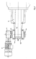
- the adjustment concept specified in SE,C,512305 has been installed at approximately 20 pulp mills, and the principle of its execution in practice is shown in Figure 3 .
- An electric motor 50 is used in this case, suspended on a ground-based frame 51.
- the tap shaft 7 is rotated through a reduction gear 52, this also being anchored to the ground-based frame, through a first connection 55 and a second connection 56.
- the connection 55 is a flexible connection that can absorb vibrations and oblique orientation between the driving unit and the shaft 7 of the tap, where the driving unit (motor and gear) is located in a support fixed to the ground and the feed casing 1 is allowed to have a certain flexibility.
- the second connection 56 and the shaft 7 of the tap are allowed through a splines connection (the female half of the splines connection is shown crosshatched in the drawing) to move to the right in Figure 3 during adjustment for wear.
- Detection of the current rotational position is carried out through a toothed wheel 53 that is attached to the shaft of the motor, and by a sensor 54 on the support that detects the rotational position of the disk 53.
- the adjustment servo as it is implemented as described in Figure 3 will be relatively expensive since several different expensive connectors are required in order to connect the shafts between the driving unit that is attached to the ground and the shaft of the tap.
- the flexible connection is very expensive since it must be able to absorb the relatively large adjustment torque without any risk for play arising at the rotational position. Adjustment costs will also be unnecessarily high since installation of the adjustment servo requires on-site preparation during the completion of the ground-based frame.
- the present invention intends to offer a cheaper, better and considerably simpler adjustment servo for the compensation of wear in the sluice feeder.
- at least one connector and two expensive connections can be eliminated.
- Preparations for installation and installation costs can be reduced to a minimum since a ground-based frame can be totally eliminated and the complete adjustment servo is instead suspended on the shaft of the tap with torque support in the feed casing.
- a splines connector can also be eliminated and replaced by a sliding bearing support that is fixed attached to the feed casing.
- an adjustment servo is obtained with the simplified design and the simplified installation procedure that costs only 1/3 - 1/5 of the equivalent cost for a previously known adjustment servo.
- the complete driving package is suspended on the shaft of the tap and accompanies the educated sliding towards the sliding bearing support during adjustment of the position of the shaft of the tap.
- the invention concerns an arrangement for a sluice feederer equivalent to the one shown in Figure 1 and as has been previously described.
- the sluice feederer is arranged to sluice material from a first upper region 4 with lower pressure to a second lower region 6 with higher pressure, where the sluice feeder comprises a rotor 3 with a rotor shaft 7 arranged in a feed casing 1 where the rotor has the form of a truncated cone arranged with rotational symmetry around the rotor shaft 7 with at least two pockets 3 in the rotor that are open radially towards the perimeter, and where the inner surface of the feed casing has a conical form congruent with that of the rotor with an inlet connected to the first region 4 and an outlet connected to the second region 6, whereby a pocket on the rotor is initially filled with material from the first upper region and, following rotation of the rotor, delivers material to the second lower region.
- the rotor is provided with an adjustment servo in a known manner for adjustment of the axial position of the rotor in the feed casing 1 in order to compensate for wear between the rotor and the feed casing hereby compensation of wear is obtained by adjustment of the axial position of the rotor such that play between the conical form of the rotor and the conical inner surface of the feed casing is reduced to a minimum.
- the adjustment servo according to the invention is shown in different views in Figures 4 , 5 , 6 and 7 , which adjustment servo comprises a driving unit 60 and a gear 61, which gear in this embodiment is a worm gear.
- the driving unit 60, 61 is arranged directly connected to the rotor shaft 7 without a ground-based frame for the driving unit, through a journal 63 and a shaft sleeve 64 fixed attached to the journal.
- the shaft sleeve 64 is fixed with respect to rotation to the rotor shaft with a conventional cotter joint.
- At least one fixed torque support (two torque supports 70a, 70b are shown in the drawings) is arranged in the feed casing 1, which torque support is arranged parallel to the rotor shaft 7 with an extent of the torque support from the feed casing 1 to the driving unit 60, 61, and that the driving unit makes contact with the torque support 70a, 70b when seen from the direction of rotation of the rotor/rotor shaft 7.
- the torque support is constituted by at least one torsionally rigid beam 70a, 70b, fixed arranged in the feed casing, preferably a hollow beam as the cross-sectional views in Figure 6 and Figure 7 make clear.
- Each beam is fixed arranged, appropriately by welding, to the relevant end of the feed casing onto a flange 80 that is attached by screwing to the feed casing using attachment screws 81.
- Figure 6 shows that the beams also have reinforcements 82 that, as is shown in Figures 4 and 5 , extend a certain distance from the beam at the free end of the beam.
- the complete torque support is thus constituted only by the flange 80, the beams 70a, 70b and the reinforcements 82, which are mounted with attachment screws 81.
- the torsionally rigid beam is designed to have an elongated surface of contact 71, 72 on the beam that is parallel with the rotor shaft.
- each beam 70a, 70b is designed with two parallel elongated contact surfaces 71 a and 71 b on both sides of the beam.
- the driving unit 60, 61 is designed with a sliding support 73a, 73b and 74a, 74b that makes contact with the elongated contact surface of the beam. In the embodiment shown, these are constituted by the end surfaces of an adjustment screw.
- the sliding support 73a, 73b and 74a, 74b straddles, in the embodiment shown, the interacting torque-absorbing beam and makes contact with the elongated contact surfaces on each side of the beam. Absorption of torque can in this way take place in both directions without any play arising.
- the sliding support is in the form of the end surfaces of adjustment screws, it is easy to adjust the play between the sliding support of the driving unit and the elongated contact surface of each beam, and to lock the adjustment screws with the locking nut shown.
- the complete driving unit will accompany the axial displacement of the rotor shaft during adjustment, while the sliding supports slide along the contact surfaces of the beam or beams 70a, 70b.
- an automated adjustment of wear can take place on the basis of time, in this case suitably with an adjustment magnitude of 0.03 - 0.4 mm, as often as an adjustment three times per day and up to an adjustment of once per four days.
- this method of adjustment has proven to be unsuitable and insensitive to changes in the process, since wear in the sluice feeder is far from uniform over a period of time, and depends on the tendency of the material being fed in at any moment to wear down the play between the rotor and the feed casing.
- the adjustment be carried out in an adaptive manner depending on a parameter of the sluice feeder that depends on operation, and that is indicative of the degree of wear.
- This parameter can be constituted by one or several of the following parameters.
- the motor torque for driving the rotor of the sluice feeder By monitoring the motor torque at a pre-determined production (rpm of the rotor), an adjustment can be initiated as soon as the motor torque constantly falls below a pre-determined threshold value during a certain minimum period. It is appropriate if the threshold value is set at a motor torque that lies 5-10% under the nominal motor torque, which nominal motor torque corresponds to the torque required at the relevant rate of revolution and initially measured play between the rotor and the casing. It is appropriate that torque measurement at the shaft or a torque measurement of the driving motor is used for detection of the motor torque, by detection of the instantaneous current supply to the electric motor (for a motor having a controlled rate of revolution).
- Sluice feeders of the relevant type most often have a return flow to the sluice feeder in order to compensate for increased wear, and in this way also for leakage of cooking liquor.
- An adjustment can be initiated by monitoring this return flow, as soon as the flow exceeds a pre-determined threshold value during a certain minimum period. It is appropriate that the threshold value is set to be a flow that lies 10-20% above the nominal flow, which corresponds to the flow required at the relevant rate of revolution and initially measured play between the rotor and the casing.
- a feedback-controlled initiation of adjustment using a parameter that indicates wear allows each adjustment to be much smaller, since a subsequent detection of the parameter can be carried once the adjustment has been made. If the relevant parameter still indicates that the wear is too large, a new adjustment can be made after only a few minutes, preferably at least 10 minutes after the previous adjustment.
- the desired nominal value can be used instead of the threshold value during such a repeated adjustment, if adjustment back to the optimal situation is desired.
Landscapes
- Paper (AREA)
- Filling Or Emptying Of Bunkers, Hoppers, And Tanks (AREA)
- Transmission Devices (AREA)
- Fluid-Damping Devices (AREA)
- Soil Working Implements (AREA)
- Vehicle Body Suspensions (AREA)
- Spinning Or Twisting Of Yarns (AREA)
- Centrifugal Separators (AREA)
- Sowing (AREA)
Applications Claiming Priority (3)
| Application Number | Priority Date | Filing Date | Title |
|---|---|---|---|
| SE0300581A SE0300581L (sv) | 2003-03-05 | 2003-03-05 | Anordning för reglering av en rotor i en roterande slussmatare |
| SE0300581 | 2003-03-05 | ||
| PCT/SE2004/000287 WO2004079086A1 (en) | 2003-03-05 | 2004-03-03 | An arrangement for adjusting rotor position in a roting sluice |
Publications (3)
| Publication Number | Publication Date |
|---|---|
| EP1601832A1 EP1601832A1 (en) | 2005-12-07 |
| EP1601832B1 EP1601832B1 (en) | 2010-10-06 |
| EP1601832B2 true EP1601832B2 (en) | 2014-05-14 |
Family
ID=20290567
Family Applications (1)
| Application Number | Title | Priority Date | Filing Date |
|---|---|---|---|
| EP04716823.2A Expired - Lifetime EP1601832B2 (en) | 2003-03-05 | 2004-03-03 | An arrangement for adjusting rotor position in a roting sluice |
Country Status (8)
| Country | Link |
|---|---|
| US (1) | US7350674B2 (sv) |
| EP (1) | EP1601832B2 (sv) |
| AT (1) | ATE483851T1 (sv) |
| BR (1) | BRPI0408102B1 (sv) |
| CA (1) | CA2517612C (sv) |
| DE (1) | DE602004029447D1 (sv) |
| SE (1) | SE0300581L (sv) |
| WO (1) | WO2004079086A1 (sv) |
Families Citing this family (10)
| Publication number | Priority date | Publication date | Assignee | Title |
|---|---|---|---|---|
| SE518897C2 (sv) * | 2001-04-17 | 2002-12-03 | Lars Obitz | System och metod för matning av fibrer från ett fiberseparationssteg vid ett första tryck till ett torkningssteg vid ett andra, lägre tryck |
| US8672588B2 (en) * | 2009-04-15 | 2014-03-18 | Andritz Inc. | Unobstructed low pressure outlet and screen grid for a high pressure feeder |
| US8377261B2 (en) * | 2009-05-04 | 2013-02-19 | Metso Paper Sweden Ab | High pressure sluice feeder |
| CN102251426B (zh) * | 2011-06-30 | 2012-12-12 | 北京化工大学 | 螺杆挤出机用机头压力流量调节装置 |
| US9929608B2 (en) | 2014-02-07 | 2018-03-27 | Nidec Motor Corporation | Stator cage for large motor |
| WO2015120093A1 (en) * | 2014-02-07 | 2015-08-13 | Nidec Motor Corporation | Internal rotor sensor having adjustable sensor carrier |
| US9523462B2 (en) | 2014-05-15 | 2016-12-20 | Andritz Inc. | Adjustment housing assembly and monitoring and support system for a rotary feeder in a cellulose chip feeding system for a continuous digester |
| SE1951117A1 (sv) * | 2019-10-01 | 2021-04-02 | Valmet Oy | Electronic scale for continuous digester feeder |
| KR102583977B1 (ko) * | 2021-05-03 | 2023-10-05 | (주) 테크윈 | 분체계량 로터리밸브장치 |
| FI20225114A1 (sv) * | 2022-02-10 | 2023-08-11 | Valmet Technologies Oy | Mätsystem av en matare |
Citations (1)
| Publication number | Priority date | Publication date | Assignee | Title |
|---|---|---|---|---|
| US3273758A (en) † | 1964-02-28 | 1966-09-20 | Bauer Bros Co | Rotary valve |
Family Cites Families (4)
| Publication number | Priority date | Publication date | Assignee | Title |
|---|---|---|---|---|
| US2161553A (en) * | 1935-09-30 | 1939-06-06 | Westberg Gustave Edward | Means of conveying and mixing comminuted material |
| US3708890A (en) * | 1970-02-05 | 1973-01-09 | Wyssmont Co Inc | Rotary air lock apparatus |
| JPH01239184A (ja) * | 1988-03-17 | 1989-09-25 | Gaderiusu Eng Service Kk | 截頭円錐ロータの軸押し込み制御方法及び装置 |
| JP2783040B2 (ja) * | 1992-01-31 | 1998-08-06 | 王子製紙株式会社 | 高圧フィーダーのローター位置制御装置及び制御方法 |
-
2003
- 2003-03-05 SE SE0300581A patent/SE0300581L/sv not_active IP Right Cessation
-
2004
- 2004-03-03 AT AT04716823T patent/ATE483851T1/de not_active IP Right Cessation
- 2004-03-03 DE DE602004029447T patent/DE602004029447D1/de not_active Expired - Lifetime
- 2004-03-03 WO PCT/SE2004/000287 patent/WO2004079086A1/en not_active Ceased
- 2004-03-03 US US10/546,642 patent/US7350674B2/en not_active Expired - Lifetime
- 2004-03-03 BR BRPI0408102-1A patent/BRPI0408102B1/pt not_active IP Right Cessation
- 2004-03-03 EP EP04716823.2A patent/EP1601832B2/en not_active Expired - Lifetime
- 2004-03-03 CA CA2517612A patent/CA2517612C/en not_active Expired - Lifetime
Patent Citations (1)
| Publication number | Priority date | Publication date | Assignee | Title |
|---|---|---|---|---|
| US3273758A (en) † | 1964-02-28 | 1966-09-20 | Bauer Bros Co | Rotary valve |
Also Published As
| Publication number | Publication date |
|---|---|
| BRPI0408102B1 (pt) | 2014-07-22 |
| SE524572C2 (sv) | 2004-08-31 |
| US20060159551A1 (en) | 2006-07-20 |
| CA2517612A1 (en) | 2004-09-16 |
| SE0300581L (sv) | 2004-08-31 |
| EP1601832B1 (en) | 2010-10-06 |
| US7350674B2 (en) | 2008-04-01 |
| CA2517612C (en) | 2012-07-10 |
| WO2004079086A1 (en) | 2004-09-16 |
| DE602004029447D1 (de) | 2010-11-18 |
| EP1601832A1 (en) | 2005-12-07 |
| ATE483851T1 (de) | 2010-10-15 |
| BRPI0408102A (pt) | 2006-03-01 |
| SE0300581D0 (sv) | 2003-03-05 |
Similar Documents
| Publication | Publication Date | Title |
|---|---|---|
| EP1601832B1 (en) | An arrangement for adjusting rotor position in a roting sluice | |
| US4391414A (en) | Cone crusher | |
| US9771682B2 (en) | Adjustment assembly for axially adjusting a rotor in a rotary feeder | |
| US4936518A (en) | Apparatus for crushing or grinding of fibrous material, in particular drum refiner | |
| CA2528773C (en) | Self-aligning and actively compensating refiner stator plate system | |
| NO178612B (no) | Fremgangsmåte ved maling av fibermateriale | |
| CN116669887A (zh) | 具有平衡装置和夹紧元件的刀具头以及具有这种刀具头的机床 | |
| FI82392B (fi) | Skivkvarn. | |
| US4533148A (en) | Sealing ring assembly for use in pulp refining equipment | |
| US8974633B2 (en) | System and method for the pumped feed of chips to a continuous digester | |
| US3158333A (en) | Grinding apparatus for fibrous materials | |
| US3311309A (en) | Method and apparatus for locking a paper pulp refiner disc | |
| US7984867B2 (en) | Device for aligning the refining disc of a refining apparatus | |
| EP3469139B1 (en) | Defibrator with separated blow valve | |
| CA3157158A1 (en) | Device and method for sealing off an overpressure area |
Legal Events
| Date | Code | Title | Description |
|---|---|---|---|
| PUAI | Public reference made under article 153(3) epc to a published international application that has entered the european phase |
Free format text: ORIGINAL CODE: 0009012 |
|
| 17P | Request for examination filed |
Effective date: 20051005 |
|
| AK | Designated contracting states |
Kind code of ref document: A1 Designated state(s): AT BE BG CH CY CZ DE DK EE ES FI FR GB GR HU IE IT LI LU MC NL PL PT RO SE SI SK TR |
|
| AX | Request for extension of the european patent |
Extension state: AL LT LV MK |
|
| DAX | Request for extension of the european patent (deleted) | ||
| RAP1 | Party data changed (applicant data changed or rights of an application transferred) |
Owner name: METSO FIBER KARLSTAD AB |
|
| 17Q | First examination report despatched |
Effective date: 20100304 |
|
| GRAP | Despatch of communication of intention to grant a patent |
Free format text: ORIGINAL CODE: EPIDOSNIGR1 |
|
| GRAS | Grant fee paid |
Free format text: ORIGINAL CODE: EPIDOSNIGR3 |
|
| GRAA | (expected) grant |
Free format text: ORIGINAL CODE: 0009210 |
|
| AK | Designated contracting states |
Kind code of ref document: B1 Designated state(s): AT BE BG CH CY CZ DE DK EE ES FI FR GB GR HU IE IT LI LU MC NL PL PT RO SE SI SK TR |
|
| REG | Reference to a national code |
Ref country code: GB Ref legal event code: FG4D |
|
| REG | Reference to a national code |
Ref country code: CH Ref legal event code: EP |
|
| REG | Reference to a national code |
Ref country code: IE Ref legal event code: FG4D |
|
| REF | Corresponds to: |
Ref document number: 602004029447 Country of ref document: DE Date of ref document: 20101118 Kind code of ref document: P |
|
| REG | Reference to a national code |
Ref country code: NL Ref legal event code: VDEP Effective date: 20101006 |
|
| PG25 | Lapsed in a contracting state [announced via postgrant information from national office to epo] |
Ref country code: SI Free format text: LAPSE BECAUSE OF FAILURE TO SUBMIT A TRANSLATION OF THE DESCRIPTION OR TO PAY THE FEE WITHIN THE PRESCRIBED TIME-LIMIT Effective date: 20101006 |
|
| PG25 | Lapsed in a contracting state [announced via postgrant information from national office to epo] |
Ref country code: AT Free format text: LAPSE BECAUSE OF FAILURE TO SUBMIT A TRANSLATION OF THE DESCRIPTION OR TO PAY THE FEE WITHIN THE PRESCRIBED TIME-LIMIT Effective date: 20101006 Ref country code: PT Free format text: LAPSE BECAUSE OF FAILURE TO SUBMIT A TRANSLATION OF THE DESCRIPTION OR TO PAY THE FEE WITHIN THE PRESCRIBED TIME-LIMIT Effective date: 20110207 Ref country code: NL Free format text: LAPSE BECAUSE OF FAILURE TO SUBMIT A TRANSLATION OF THE DESCRIPTION OR TO PAY THE FEE WITHIN THE PRESCRIBED TIME-LIMIT Effective date: 20101006 Ref country code: BG Free format text: LAPSE BECAUSE OF FAILURE TO SUBMIT A TRANSLATION OF THE DESCRIPTION OR TO PAY THE FEE WITHIN THE PRESCRIBED TIME-LIMIT Effective date: 20110106 Ref country code: SE Free format text: LAPSE BECAUSE OF FAILURE TO SUBMIT A TRANSLATION OF THE DESCRIPTION OR TO PAY THE FEE WITHIN THE PRESCRIBED TIME-LIMIT Effective date: 20101006 |
|
| PG25 | Lapsed in a contracting state [announced via postgrant information from national office to epo] |
Ref country code: BE Free format text: LAPSE BECAUSE OF FAILURE TO SUBMIT A TRANSLATION OF THE DESCRIPTION OR TO PAY THE FEE WITHIN THE PRESCRIBED TIME-LIMIT Effective date: 20101006 Ref country code: GR Free format text: LAPSE BECAUSE OF FAILURE TO SUBMIT A TRANSLATION OF THE DESCRIPTION OR TO PAY THE FEE WITHIN THE PRESCRIBED TIME-LIMIT Effective date: 20110107 |
|
| PLBI | Opposition filed |
Free format text: ORIGINAL CODE: 0009260 |
|
| PG25 | Lapsed in a contracting state [announced via postgrant information from national office to epo] |
Ref country code: CZ Free format text: LAPSE BECAUSE OF FAILURE TO SUBMIT A TRANSLATION OF THE DESCRIPTION OR TO PAY THE FEE WITHIN THE PRESCRIBED TIME-LIMIT Effective date: 20101006 Ref country code: EE Free format text: LAPSE BECAUSE OF FAILURE TO SUBMIT A TRANSLATION OF THE DESCRIPTION OR TO PAY THE FEE WITHIN THE PRESCRIBED TIME-LIMIT Effective date: 20101006 Ref country code: ES Free format text: LAPSE BECAUSE OF FAILURE TO SUBMIT A TRANSLATION OF THE DESCRIPTION OR TO PAY THE FEE WITHIN THE PRESCRIBED TIME-LIMIT Effective date: 20110117 |
|
| PLAX | Notice of opposition and request to file observation + time limit sent |
Free format text: ORIGINAL CODE: EPIDOSNOBS2 |
|
| 26 | Opposition filed |
Opponent name: ANDRITZ, INC. Effective date: 20110706 |
|
| PG25 | Lapsed in a contracting state [announced via postgrant information from national office to epo] |
Ref country code: RO Free format text: LAPSE BECAUSE OF FAILURE TO SUBMIT A TRANSLATION OF THE DESCRIPTION OR TO PAY THE FEE WITHIN THE PRESCRIBED TIME-LIMIT Effective date: 20101006 Ref country code: DK Free format text: LAPSE BECAUSE OF FAILURE TO SUBMIT A TRANSLATION OF THE DESCRIPTION OR TO PAY THE FEE WITHIN THE PRESCRIBED TIME-LIMIT Effective date: 20101006 Ref country code: PL Free format text: LAPSE BECAUSE OF FAILURE TO SUBMIT A TRANSLATION OF THE DESCRIPTION OR TO PAY THE FEE WITHIN THE PRESCRIBED TIME-LIMIT Effective date: 20101006 Ref country code: SK Free format text: LAPSE BECAUSE OF FAILURE TO SUBMIT A TRANSLATION OF THE DESCRIPTION OR TO PAY THE FEE WITHIN THE PRESCRIBED TIME-LIMIT Effective date: 20101006 |
|
| REG | Reference to a national code |
Ref country code: DE Ref legal event code: R026 Ref document number: 602004029447 Country of ref document: DE Effective date: 20110706 |
|
| PG25 | Lapsed in a contracting state [announced via postgrant information from national office to epo] |
Ref country code: MC Free format text: LAPSE BECAUSE OF NON-PAYMENT OF DUE FEES Effective date: 20110331 |
|
| REG | Reference to a national code |
Ref country code: CH Ref legal event code: PL |
|
| PLBB | Reply of patent proprietor to notice(s) of opposition received |
Free format text: ORIGINAL CODE: EPIDOSNOBS3 |
|
| GBPC | Gb: european patent ceased through non-payment of renewal fee |
Effective date: 20110303 |
|
| REG | Reference to a national code |
Ref country code: FR Ref legal event code: ST Effective date: 20111130 |
|
| PG25 | Lapsed in a contracting state [announced via postgrant information from national office to epo] |
Ref country code: IT Free format text: LAPSE BECAUSE OF FAILURE TO SUBMIT A TRANSLATION OF THE DESCRIPTION OR TO PAY THE FEE WITHIN THE PRESCRIBED TIME-LIMIT Effective date: 20101006 |
|
| REG | Reference to a national code |
Ref country code: IE Ref legal event code: MM4A |
|
| PG25 | Lapsed in a contracting state [announced via postgrant information from national office to epo] |
Ref country code: DE Free format text: LAPSE BECAUSE OF NON-PAYMENT OF DUE FEES Effective date: 20111001 Ref country code: LI Free format text: LAPSE BECAUSE OF NON-PAYMENT OF DUE FEES Effective date: 20110331 Ref country code: IE Free format text: LAPSE BECAUSE OF NON-PAYMENT OF DUE FEES Effective date: 20110303 Ref country code: CH Free format text: LAPSE BECAUSE OF NON-PAYMENT OF DUE FEES Effective date: 20110331 Ref country code: FR Free format text: LAPSE BECAUSE OF NON-PAYMENT OF DUE FEES Effective date: 20110331 |
|
| REG | Reference to a national code |
Ref country code: DE Ref legal event code: R119 Ref document number: 602004029447 Country of ref document: DE Effective date: 20111001 |
|
| PG25 | Lapsed in a contracting state [announced via postgrant information from national office to epo] |
Ref country code: GB Free format text: LAPSE BECAUSE OF NON-PAYMENT OF DUE FEES Effective date: 20110303 |
|
| RAP2 | Party data changed (patent owner data changed or rights of a patent transferred) |
Owner name: METSO PAPER SWEDEN AB |
|
| PG25 | Lapsed in a contracting state [announced via postgrant information from national office to epo] |
Ref country code: LU Free format text: LAPSE BECAUSE OF NON-PAYMENT OF DUE FEES Effective date: 20110303 Ref country code: CY Free format text: LAPSE BECAUSE OF FAILURE TO SUBMIT A TRANSLATION OF THE DESCRIPTION OR TO PAY THE FEE WITHIN THE PRESCRIBED TIME-LIMIT Effective date: 20101006 |
|
| PG25 | Lapsed in a contracting state [announced via postgrant information from national office to epo] |
Ref country code: TR Free format text: LAPSE BECAUSE OF FAILURE TO SUBMIT A TRANSLATION OF THE DESCRIPTION OR TO PAY THE FEE WITHIN THE PRESCRIBED TIME-LIMIT Effective date: 20101006 |
|
| PG25 | Lapsed in a contracting state [announced via postgrant information from national office to epo] |
Ref country code: HU Free format text: LAPSE BECAUSE OF FAILURE TO SUBMIT A TRANSLATION OF THE DESCRIPTION OR TO PAY THE FEE WITHIN THE PRESCRIBED TIME-LIMIT Effective date: 20101006 |
|
| PUAH | Patent maintained in amended form |
Free format text: ORIGINAL CODE: 0009272 |
|
| STAA | Information on the status of an ep patent application or granted ep patent |
Free format text: STATUS: PATENT MAINTAINED AS AMENDED |
|
| 27A | Patent maintained in amended form |
Effective date: 20140514 |
|
| AK | Designated contracting states |
Kind code of ref document: B2 Designated state(s): AT BE BG CH CY CZ DE DK EE ES FI FR GB GR HU IE IT LI LU MC NL PL PT RO SE SI SK TR |
|
| REG | Reference to a national code |
Ref country code: DE Ref legal event code: R102 Ref document number: 602004029447 Country of ref document: DE |
|
| REG | Reference to a national code |
Ref country code: DE Ref legal event code: R102 Ref document number: 602004029447 Country of ref document: DE Effective date: 20140514 |
|
| PGFP | Annual fee paid to national office [announced via postgrant information from national office to epo] |
Ref country code: FI Payment date: 20230315 Year of fee payment: 20 |