EP1601837B1 - Une unité cyclone avec une trémie - Google Patents
Une unité cyclone avec une trémie Download PDFInfo
- Publication number
- EP1601837B1 EP1601837B1 EP04720079.5A EP04720079A EP1601837B1 EP 1601837 B1 EP1601837 B1 EP 1601837B1 EP 04720079 A EP04720079 A EP 04720079A EP 1601837 B1 EP1601837 B1 EP 1601837B1
- Authority
- EP
- European Patent Office
- Prior art keywords
- hopper
- cyclone unit
- cyclone
- mesh screen
- actuator mechanism
- Prior art date
- Legal status (The legal status is an assumption and is not a legal conclusion. Google has not performed a legal analysis and makes no representation as to the accuracy of the status listed.)
- Expired - Lifetime
Links
- 230000007246 mechanism Effects 0.000 claims description 61
- 238000010408 sweeping Methods 0.000 claims description 33
- 238000004140 cleaning Methods 0.000 claims description 13
- 238000000034 method Methods 0.000 claims description 8
- 239000000463 material Substances 0.000 description 18
- 239000000428 dust Substances 0.000 description 9
- XLYOFNOQVPJJNP-UHFFFAOYSA-N water Substances O XLYOFNOQVPJJNP-UHFFFAOYSA-N 0.000 description 9
- 241001417527 Pempheridae Species 0.000 description 4
- 229910000831 Steel Inorganic materials 0.000 description 2
- 230000000694 effects Effects 0.000 description 2
- 239000000203 mixture Substances 0.000 description 2
- 239000010959 steel Substances 0.000 description 2
- 238000013022 venting Methods 0.000 description 2
- 239000003570 air Substances 0.000 description 1
- 238000001914 filtration Methods 0.000 description 1
- 230000001771 impaired effect Effects 0.000 description 1
- 238000012986 modification Methods 0.000 description 1
- 230000004048 modification Effects 0.000 description 1
- JTJMJGYZQZDUJJ-UHFFFAOYSA-N phencyclidine Chemical class C1CCCCN1C1(C=2C=CC=CC=2)CCCCC1 JTJMJGYZQZDUJJ-UHFFFAOYSA-N 0.000 description 1
- 238000000926 separation method Methods 0.000 description 1
- 239000007787 solid Substances 0.000 description 1
- 125000006850 spacer group Chemical group 0.000 description 1
- 238000009987 spinning Methods 0.000 description 1
- 230000001629 suppression Effects 0.000 description 1
- 238000010407 vacuum cleaning Methods 0.000 description 1
- 238000009736 wetting Methods 0.000 description 1
Images


Classifications
-
- E—FIXED CONSTRUCTIONS
- E01—CONSTRUCTION OF ROADS, RAILWAYS, OR BRIDGES
- E01H—STREET CLEANING; CLEANING OF PERMANENT WAYS; CLEANING BEACHES; DISPERSING OR PREVENTING FOG IN GENERAL CLEANING STREET OR RAILWAY FURNITURE OR TUNNEL WALLS
- E01H1/00—Removing undesirable matter from roads or like surfaces, with or without moistening of the surface
- E01H1/02—Brushing apparatus, e.g. with auxiliary instruments for mechanically loosening dirt
- E01H1/04—Brushing apparatus, e.g. with auxiliary instruments for mechanically loosening dirt taking- up the sweepings, e.g. for collecting, for loading
- E01H1/047—Collecting apparatus characterised by the hopper or by means for unloading the hopper
Definitions
- the present invention relates to a cyclone unit with a hopper for a suction sweeping machine including an opening mechanism, in particular for assisting in the cleaning of motorised suction sweeping machines used for clearing dirt and litter from streets and roads.
- the present invention also provides a method for tipping the hopper of a suction sweeping machine comprising such a cyclone unit with a hopper.
- a suction sweeping machine generally comprises front rotary sweepers for gathering the dust and the like, water sprayers for wetting the dust and the like in dry weather, and a vacuum cleaning or suction mechanism for sucking the wetted dust and the like into the machine for collection in a hopper via a suction hose. Once the hopper is full, the machine is emptied and, if required, cleaned.
- cyclone units are provided for removing fine or small dirt and the like from the airflow generated by a main vacuum fan. Larger dirt and litter, which would damage the cyclone unit, is prevented from entering the cyclone unit by a mesh screen. The cleaned air is then vented from the machine, while the dirt and litter that has been extracted from the airflow is thrown by the cyclone unit into the hopper.
- the hopper i.e. a container for collecting the dirt ant litter, when full, needs to be emptied. At the end of the day, the hopper is additionally cleaned.
- the cyclone unit however, is a sealed unit. Therefore it is difficult to clean.
- the present invention provides a cyclone unit and hopper according to claim 1.
- the present invention also provides a suction sweeping machine comprising a cyclone unit with a hopper as defined in claim 1.
- the base has a portion of a mesh screen attached thereto, the mesh screen forming a filter for the cyclone unit.
- the actuator mechanism comprises a hydraulic piston.
- the actuator mechanism is attached at one end to the inside of the hopper, and more preferably to the roof of the hopper.
- the actuator mechanism is attached at one end to a lid or door of the hopper.
- the actuator mechanism is attached at one end to a removable base of the cyclone unit.
- the actuator mechanism is attached at one end to the removable base of the cyclone unit via a hinged portion of a mesh screen for the cyclone unit, the base being attached to the hinged portion of the mesh screen.
- the actuator mechanism is attached to the lid or door of the hopper via a linkage mechanism.
- the actuator mechanism is attached to the mesh screen, or the base of the cyclone unit, or both, via a linkage mechanism.
- the linkage mechanism is attached to both the mesh screen and the lid or door of the hopper.
- the lid or door is rotated by about 60°.
- the actuator mechanism upon actuation, will rotate the mesh screen and base of the cyclone unit. Preferably they are rotated by about 34.4°.
- the lid or door is hinged towards the front of the hopper.
- the hopper is positioned towards the rear of the suction sweeping machine.
- the mesh screen is attached to the base of the cyclone unit using spacers to provide an air gap between the base of the cyclone unit and the hinged portion of the mesh screen.
- the air gap is about 20mm.
- the cyclone unit is inside the hopper.
- the cyclone unit is positioned towards the top and front of the hopper.
- the cyclone unit comprises an air vent for venting air to the atmosphere, out of the hopper.
- the air vent is positioned towards the top of the hopper.
- the mesh screen effectively extends across the entire horizontal area of the hopper, just below the top thereof.
- the mesh screen is in two parts.
- a first part extends substantially horizontally, in its closed position, below the or each cyclone unit.
- a second part extends substantially horizontally, in its closed position, below the lid or door of the hopper.
- both parts are hinged.
- the first part is rotated by the actuator mechanism.
- the second part is hinged adjacent the junction thereof with the first part.
- the junction extends laterally across the hopper.
- the first part is hinged adjacent the front of the hopper, parallel to the hinge of the second part.
- a portion of the second part of the mesh screen is provided on the underside of the lid or door of the hopper, so that it is opened as the lid or door of the hopper is opened by the actuator mechanism.
- a pair of cyclone units is provided.
- the cyclone units are laterally spaced.
- the actuator mechanism is positioned between the two cyclone units.
- the hopper comprises a tipper mechanism for tipping the hopper about a hinge point for emptying the contents thereof through the lid or door of the hopper once the lid or door of the hopper has been opened by the actuator mechanism.
- the lid or door of the hopper is provided at the top of the hopper in its untipped position.
- the lid or door opens such that it moves away from the hinge point.
- the mesh screen is rotated such that it moves away from the hinge point.
- the present invention also provides a method for tipping a hopper of a suction sweeping machine as defined in claim 16.
- the hopper to tip out its contents, is rotated up and over the hinge point by about 110°.
- the hopper upon starting to tip the hopper, the hopper is moved rearwardly and upwards, while being rotated, to move it out of the suction sweeping machine such that, in its tipped position, it will hang substantially upside down, above and clear of the suction sweeping machine.
- the opening mechanism opens a lid or door of the hopper and opens a base of the cyclone unit to move them into a cleaning position prior to tipping of the hopper.
- FIG 3 there is shown a small sweeper or suction sweeping machine 10 that uses a centrifugal fan (not shown) to suck up dirt and dust in all weathers. It passes the dirt and dust via a pick up hose (not shown) through the fan, which compacts this material and blows it into a hopper 12. Once the hopper 12 is full, the hopper is emptied by tipping out its contents. The hopper 12 is shown in its tipping position 20 and its non tipping position 22. Instead of a fan through which the dirt passes, however, the system may operate using a vacuum source to pull the dirt into the hopper.
- the mixing and compacting properties of the fan agglomerates the majority of the dry/dusty material swept and sucked up off the ground to form heavy dirt before it enters the hopper.
- a system of baffles in the main body of the hopper spins the material, air and water mixture in the hopper, creating a cyclone effect.
- the baffles are placed in the corners of the hopper and when air, water, dirt and dust enter the hopper, it does so at the near side of the hopper. Together with the baffles the mixture is set spinning with the heavy dirt being thrown against the walls of the hopper and lighter material settling into the 'dead' air area at the centre of the hopper.
- a sample device incorporating this technology is the original Applied 525 sweeping machine, from the present applicants. Further description of this basic cyclone effect, therefore, is not required.
- the machine shown in figure 3 comprises a secondary cleaning system not found in the original Applied 525 sweeping machine.
- the hopper 12 is again shown, but in more detail.
- the hopper 12 has therein a pair of cyclone units 16 (one shown).
- a cyclone unit 16 is provided on each side of the machine 10.
- a mesh screen 18 is provided inside the hopper 12 to extend substantially across the entire horizontal extent of the hopper 12, just below the top 50 of the hopper 12, but below the cyclone units 16.
- the mesh screen 18 is shown to comprise multiple component parts 18', 18", 18"'. They are all hinged so that they can be opened for cleaning both sides thereof.
- a first part is positioned below the cyclone units 16. It is shown in an open or downwardly rotated position 18' as well as the closed position. It can be rotated about a hinge 19 adjacent the front of the hopper 12. When the cyclone units are operating, however, this part of the mesh screen 18 will be closed (reference sign 30 in figure 5 ).
- a second part 18" is provided on the underside of the lid or door 24 of the hopper 12. It is hinged adjacent the hinge 23 of the lid or door 24.
- the third part 18'" is hinged about a laterally extending hinge 25 towards the middle of the hopper 12.
- Cyclone units are normally designed individually to handle a certain flow of air at a certain pressure.
- the material the cyclones are designed to separate normally does not change. It is either wet or dry and normally of a pre-determined size.
- the material passing through the mesh screens 18 into the cyclone units 16 will be dry or wet depending on the conditions of the street.
- the cyclone unit shown in figures 1 and 2 will handle both wet and dry dirt.
- each cyclone unit 16 comprises stationary, angled blades (or fins) 32, a spinner 34 underneath them (shown more clearly in Figure 5 ), and a central air venting core.
- the spinner comprises four arms 40 (one shown having a paddle on the end - each arm, however, will generally have a paddle).
- the side wall of the cyclone unit 16 has at least one dirt slot 38 therein for the dirt to exit the cyclone unit 16.
- the base of the cyclone unit 16 is made of a solid steel plate 39. The plate 39 can be moved relative to the rest of the cyclone unit 16 to open up the cyclone unit for cleaning it.
- the dusty or dirty air will enter 31 the cyclone units 16. Then it passes through the angled blades 32. They cause the air to spin at high speed around the cyclone unit 16.
- the slot or slots 38 in the external wall of the cyclone units then allows the heavier than air material to pass out of the cyclone unit for collection in the hopper 12.
- the spinner 34 (a propeller-like unit) spins with the air causing the 'boundary' air in the cyclone unit to be at a higher velocity and so more efficient at displacing the dirt therefrom.
- the cleaned air will then pass to the inside of the cyclone unit and exit 33 upwards through the central core 36.
- the heavier than air material passing out of the cyclone unit for collection in the hopper 12 may pass back through the mesh into the hopper or may collect on the cyclone unit side of the mesh screen 18.
- cyclone units 16 will be readily understood by a skilled person in the art of cyclone based dirt/air separation units. Therefore further description of the cyclone units 16 is not required.
- the present invention provides a mechanism for facilitating the cleaning operation of the internal mechanisms of the hopper and cyclone unit.
- the base of the cyclone unit 16 (steel plate 39), which is attached to the hinged part 18' of the mesh screen 18, swings down and away from the rest of the cyclone unit 16 to open up the interior of the cyclone unit 16. This facilitates the cleaning of the interior of the cyclone unit 16.
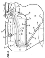
- an actuator mechanism 42 In order to operate the opening of the mesh screen, an actuator mechanism 42 is provided.
- the actuator mechanism 42 comprises a hydraulic cylinder 44 attached at a first end 46 to a bracket 48 on the inside surface 50 of the roof of the hopper 12.
- a piston 52 At the other end of the cylinder 44 there is a piston 52, operable with the cylinder 44 to form a hydraulic ram.
- the piston 52 connects at its operative end 54, i.e. the end distal to the first end 46 of the cylinder 44, to a linkage mechanism 56 that is operatively connected to both a lid or door 24 for the hopper 12 and the hinged part 18' of the mesh screen 18.
- the linkage mechanism 56 comprises a link arm that is connected to both a lever arm for the lid or door 24 of the hopper 12 and to a lever arm 60 for the hinged part 18' of the mesh screen 18.
- the lengths of the two lever arms are different so that the angles to which the lid or door 24 and the hinged part 18' of the mesh screen 18 will open upon operation of the actuating mechanism will be different.
- the angles are shown to be 60° and 34.4°, respectively.
- Reference sign 56 is for the open position.
- Reference sign 56' represents an intermediate position.
- Reference sign 56" represents a closed position.
- the suction sweeping machine also comprises a tipping mechanism for the hopper 12.
- the tipping mechanism comprises a hinge arm 62 that is welded or bolted to the rear wall 64 of the hopper 12.
- the hinge arm has a hinge point 66 positioned substantially towards the rear and top of the hopper.
- a hydraulic ram (not shown) operates against the hinge arm 62 to rotate the hopper 12 up and over the hinge point 66 by about 110° into an inverted and raised position (tipping position 20) as shown in figure 3 .
- the suction sweeping machine is first positioned such that it is backed up to a skip, or the like, for receiving the dirt from the hopper 12. Then a user operates the tipping mechanism to tip out the contents of the hopper 12 into the skip.
- the actuator mechanism for the door 24 of the hopper and the hinged part 18' of the mesh screen 18 will be operable in conjunction with the tipping mechanism such that the actuator mechanism can be operated either before the tipper mechanism is operated, or as the tipper mechanism is operated.
- the hopper 12, the mesh screen 18 and the cyclone units 16 will need to be washed out.
- a user after tipping out the contents of the hopper 12 as best as possible by operating the tipping mechanism while the machine is positioned backed up to the skip, will move the machine 10 forward without untipping the hopper to allow him to stand behind the machine 10. The user will then wash down the inside of the hopper 12, for example using a high pressure hose.
- the hopper 12 is rotated to be positioned above and behind the suction sweeping machine 10. Further, the lid or door 24 of the hopper 12 is opened. Further, the mesh screen 18 will also be open.
- These three features provide for simple access to the dirty parts of the internal mechanisms of the hopper, the mesh screen and cyclone units, thereby facilitating the cleaning process for the hopper, the mesh screen and the cyclone units; access to the inside of the hopper 12 and both surfaces of each part of the mesh screen 18 is provided through the lid or door of the hopper since the mesh screen parts are hinged so that water can be sprayed on the inside surface of the hopper 12 and also the both surfaces 26 of the various parts of the mesh screen 18 to displace any accumulated dirt from the outside surface 28 of the mesh screen 18 - water can push through the mesh screen to force out entrapped dirt. Further, with a hooked hose, the inside of the cyclone unit can also be washed out easily.
- the present invention makes the cyclone units and the mesh screen, i.e. the filters, split or open automatically whenever the machine is emptied. This facilitates the cleaning of the internal components of the suction sweeping machine 10, and in particular otherwise inaccessible areas and components of the machine 10.
Landscapes
- Engineering & Computer Science (AREA)
- Architecture (AREA)
- Civil Engineering (AREA)
- Structural Engineering (AREA)
- Cyclones (AREA)
- Cleaning In General (AREA)
Claims (19)
- Unité de cyclone avec une trémie (12) pour une balayeuse aspirante (10), comprenant un mécanisme d'ouverture comprenant un mécanisme d'actionnement (42) pour ouvrir à la fois l'unité de cyclone et la trémie (12) pour nettoyer l'unité de cyclone et la trémie (12) ;
caractérisée en ce que :le mécanisme d'actionnement, suite à l'actionnement, ouvre un couvercle ou porte de la trémie en le faisant tourner et une base de l'unité de cyclone est déplacée par le mécanisme d'actionnement par rapport au reste de l'unité de cyclone pour ouvrir l'unité de cyclone. - Unité de cyclone avec une trémie selon la revendication 1, dans laquelle le mécanisme d'actionnement (42) est fixé au niveau d'une extrémité à l'intérieur de la trémie (12).
- Unité de cyclone avec une trémie selon la revendication 1 ou la revendication 2, dans laquelle le mécanisme d'actionnement (42) est fixé, au niveau d'une extrémité, au couvercle ou à la porte (24) de la trémie (12).
- Unité de cyclone avec une trémie selon l'une quelconque des revendications 1 à 3, dans laquelle le mécanisme d'actionnement (42) est fixé, au niveau d'une extrémité, à la base de l'unité de cyclone (16).
- Unité de cyclone avec une trémie selon l'une quelconque des revendications 1 à 4, dans laquelle le mécanisme d'actionnement (42) est fixé, au niveau d'une extrémité, à un tamis à mailles (18), la base de l'unité de cyclone (16) étant fixée au tamis à mailles (18).
- Unité de cyclone avec une trémie selon l'une quelconque des revendications 1 à 5, dans laquelle le mécanisme d'actionnement (42) est fixé au couvercle ou à la porte (24) de la trémie (12) via un mécanisme de tringlerie.
- Unité de cyclone avec une trémie selon l'une quelconque des revendications 1 à 6, dans laquelle le mécanisme d'actionnement (42) est fixé à la base de l'unité de cyclone (16) via un mécanisme de tringlerie.
- Unité de cyclone avec une trémie selon l'une quelconque des revendications 1 à 7, dans laquelle il n'y a qu'un seul actionneur dans le mécanisme d'actionnement (42).
- Unité de cyclone avec une trémie selon l'une quelconque des revendications 1 à 7, dans laquelle l'unité de cyclone (16) est à l'intérieur de la trémie (12).
- Unité de cyclone avec une trémie selon l'une quelconque des revendications 1 à 9, dans laquelle l'unité de cyclone (16) est l'une d'une paire d'unités de cyclone (16) et le mécanisme d'actionnement (42) est positionné entre la paire d'unités de cyclone (16).
- Unité de cyclone avec une trémie selon l'une quelconque des revendications 1 à 10, dans laquelle la trémie (12) comprend un mécanisme de basculement pour faire basculer la trémie (12) et l'unité de cyclone (16) pour vider le contenu éventuel de la trémie par un couvercle ou une porte (24) de la trémie (12), une fois que le couvercle ou la porte (24) de la trémie (12) a été ouvert(e) par le mécanisme d'actionnement (42).
- Balayeuse aspirante comprenant une unité de cyclone avec une trémie selon la revendication 1.
- Balayeuse aspirante selon la revendication 12, dans laquelle le mécanisme d'actionnement fait également tourner un tamis à mailles pour nettoyer une surface inaccessible du tamis à mailles.
- Balayeuse aspirante selon la revendication 13, dans laquelle le tamis à mailles fait partie d'un filtre pour l'unité de cyclone.
- Balayeuse aspirante selon la revendication 13 ou 14, dans laquelle la base de l'unité de cyclone est fixée au tamis à mailles.
- Procédé pour faire basculer la trémie (12) d'une balayeuse aspirante (10) selon l'une quelconque des revendications 12 à 15, dans lequel la trémie (12) comprend un mécanisme de basculement pour faire basculer la trémie (12) et l'unité de cyclone (16) afin de vider le contenu éventuel de la trémie par le couvercle ou la porte (24) de la trémie (12) une fois que le couvercle ou la porte (24) de la trémie (12) a été ouvert(e) par le mécanisme d'actionnement (42),
la trémie (12) étant positionnée vers l'arrière de la balayeuse aspirante (10), le procédé comprenant l'étape consistant à actionner le mécanisme de basculement pour basculer la trémie (12) autour d'une charnière positionnée sensiblement vers la partie supérieure et arrière de la balayeuse aspirante (10). - Procédé selon la revendication 16, dans lequel l'unité de cyclone (16) est à l'intérieur de la trémie (12) lorsque la trémie est basculée.
- Procédé selon la revendication 16 ou 17, dans lequel la trémie (12), pour basculer son contenu éventuel, est entraînée en rotation à environ 110°.
- Procédé selon la revendication 16 ou la revendication 17, dans lequel, après avoir commencé le basculement de la trémie (12), la trémie (12) est déplacée vers l'arrière et vers le haut, tout en étant entraînée en rotation, pour la faire sortir de la balayeuse aspirante (10), de sorte que, dans sa position basculée, elle est suspendue sensiblement à l'envers, au-dessus et dégagée de la balayeuse aspirante (10).
Applications Claiming Priority (3)
| Application Number | Priority Date | Filing Date | Title |
|---|---|---|---|
| GB0305664 | 2003-03-12 | ||
| GBGB0305664.5A GB0305664D0 (en) | 2003-03-12 | 2003-03-12 | Hopper opening mechanism |
| PCT/GB2004/001077 WO2004081289A1 (fr) | 2003-03-12 | 2004-03-12 | Mecanisme servant a ouvrir une tremie |
Publications (2)
| Publication Number | Publication Date |
|---|---|
| EP1601837A1 EP1601837A1 (fr) | 2005-12-07 |
| EP1601837B1 true EP1601837B1 (fr) | 2013-09-04 |
Family
ID=9954638
Family Applications (1)
| Application Number | Title | Priority Date | Filing Date |
|---|---|---|---|
| EP04720079.5A Expired - Lifetime EP1601837B1 (fr) | 2003-03-12 | 2004-03-12 | Une unité cyclone avec une trémie |
Country Status (6)
| Country | Link |
|---|---|
| US (1) | US7712181B2 (fr) |
| EP (1) | EP1601837B1 (fr) |
| AU (1) | AU2004219896B2 (fr) |
| CA (1) | CA2515352C (fr) |
| GB (1) | GB0305664D0 (fr) |
| WO (1) | WO2004081289A1 (fr) |
Families Citing this family (17)
| Publication number | Priority date | Publication date | Assignee | Title |
|---|---|---|---|---|
| US7533435B2 (en) | 2003-05-14 | 2009-05-19 | Karcher North America, Inc. | Floor treatment apparatus |
| US20120096671A1 (en) | 2010-10-26 | 2012-04-26 | Karcher North America, Inc. | Floor cleaning apparatus employing a combined sweeper and vaccum assembly |
| US8302240B2 (en) * | 2009-07-29 | 2012-11-06 | Karcher North America, Inc. | Selectively adjustable steering mechanism for use on a floor cleaning machine |
| GB0426710D0 (en) * | 2004-12-06 | 2005-01-12 | Applied Sweepers Ltd | Dust control system |
| DE102007038677B4 (de) | 2007-08-15 | 2009-09-17 | Wirtgen Gmbh | Abstreifeinrichtung, sowie Baumaschine |
| WO2009108955A1 (fr) * | 2008-02-29 | 2009-09-03 | Tennant Company | Ensemble trémie équipé d'un module filtre pour machine d'entretien de surface |
| GB2463288B (en) | 2008-09-09 | 2013-03-27 | Tennant N V | Sweeping machine with location monitoring and charging |
| US9795913B1 (en) * | 2009-06-26 | 2017-10-24 | Exact Corporation | System for removing particles from an air stream |
| US9821953B2 (en) | 2011-05-02 | 2017-11-21 | The Charles Machine Works, Inc. | Apparatus for sealing a vacuum tank door |
| US9057180B1 (en) * | 2011-05-02 | 2015-06-16 | The Charles Machine Works, Inc. | Apparatus for sealing a vacuum tank door |
| CN102493387B (zh) * | 2011-12-27 | 2013-12-25 | 黄宇 | 模块化通用车载清路装置 |
| US10221602B2 (en) | 2016-04-06 | 2019-03-05 | The Charles Machine Works, Inc. | Vacuum system |
| EP3618676B1 (fr) | 2017-05-04 | 2023-09-20 | Alfred Kärcher SE & Co. KG | Appareil de nettoyage de sol et méthode de nettoyage d'une surface au sol |
| US11059682B2 (en) | 2017-12-21 | 2021-07-13 | The Charles Machine Works, Inc. | Offloading vacuum tank |
| USD895914S1 (en) | 2018-02-15 | 2020-09-08 | The Charles Machine Works, Inc. | Vacuum system |
| USD907868S1 (en) | 2019-01-24 | 2021-01-12 | Karcher North America, Inc. | Floor cleaner |
| US11395984B2 (en) | 2019-05-24 | 2022-07-26 | Flory Industries | Dust control system and related methods |
Citations (1)
| Publication number | Priority date | Publication date | Assignee | Title |
|---|---|---|---|---|
| US4574420A (en) * | 1984-02-24 | 1986-03-11 | Nfe International, Ltd. | Versatile particle collector apparatus |
Family Cites Families (11)
| Publication number | Priority date | Publication date | Assignee | Title |
|---|---|---|---|---|
| GB923960A (en) * | 1960-03-28 | 1963-04-18 | Asbrink & Co Ab | Improvements in or relating to mobile pneumatic cleaning devices |
| US3406423A (en) * | 1967-01-30 | 1968-10-22 | Werner W. Young | Street cleaning machine |
| US4218226A (en) * | 1978-07-25 | 1980-08-19 | Link Built Products of Ocala, Inc. | Vacuum apparatus |
| US5113548A (en) * | 1988-04-29 | 1992-05-19 | Tymco, Inc. | Surface sweeping machine with over-the-cab hopper dumping |
| US5303448A (en) | 1992-07-08 | 1994-04-19 | Tennant Company | Hopper and filter chamber for direct forward throw sweeper |
| US5596788A (en) | 1994-11-14 | 1997-01-28 | Linville; Ronny E. | Vacuum sweeper vehicle with lightweight hopper |
| GB2306345B (en) * | 1995-10-20 | 1999-06-23 | Applied Sweepers Ltd | Suction sweeping machine |
| JP3704848B2 (ja) | 1996-12-12 | 2005-10-12 | 豊和工業株式会社 | 空気流清掃車 |
| DE10118500C1 (de) * | 2001-04-12 | 2002-08-22 | Kuepper Weisser Gmbh | Kehrgutbehälter für Kehrmaschinenfahrzeug |
| US6742219B2 (en) * | 2001-10-29 | 2004-06-01 | Tennant Company | Air sweeping apparatus |
| US6966097B2 (en) * | 2002-09-06 | 2005-11-22 | Tennant Company | Street sweeper with dust control |
-
2003
- 2003-03-12 GB GBGB0305664.5A patent/GB0305664D0/en not_active Ceased
-
2004
- 2004-03-12 CA CA2515352A patent/CA2515352C/fr not_active Expired - Fee Related
- 2004-03-12 US US10/548,899 patent/US7712181B2/en not_active Expired - Fee Related
- 2004-03-12 WO PCT/GB2004/001077 patent/WO2004081289A1/fr not_active Ceased
- 2004-03-12 AU AU2004219896A patent/AU2004219896B2/en not_active Ceased
- 2004-03-12 EP EP04720079.5A patent/EP1601837B1/fr not_active Expired - Lifetime
Patent Citations (1)
| Publication number | Priority date | Publication date | Assignee | Title |
|---|---|---|---|---|
| US4574420A (en) * | 1984-02-24 | 1986-03-11 | Nfe International, Ltd. | Versatile particle collector apparatus |
Also Published As
| Publication number | Publication date |
|---|---|
| US20060236497A1 (en) | 2006-10-26 |
| WO2004081289A1 (fr) | 2004-09-23 |
| EP1601837A1 (fr) | 2005-12-07 |
| US7712181B2 (en) | 2010-05-11 |
| CA2515352A1 (fr) | 2004-09-23 |
| WO2004081289B1 (fr) | 2004-11-11 |
| GB0305664D0 (en) | 2003-04-16 |
| CA2515352C (fr) | 2012-10-16 |
| AU2004219896A1 (en) | 2004-09-23 |
| AU2004219896B2 (en) | 2010-11-18 |
Similar Documents
| Publication | Publication Date | Title |
|---|---|---|
| EP1601837B1 (fr) | Une unité cyclone avec une trémie | |
| US6444003B1 (en) | Filter apparatus for sweeper truck hopper | |
| US6195837B1 (en) | Debris suctioning and separating apparatus for use in a surface sweeping vehicle having a mechanical debris elevator | |
| JP2933467B2 (ja) | 直接前方放り投げ式スイーパ | |
| US3186021A (en) | Power sweeper | |
| US4193159A (en) | Mobile cleaning apparatus for removing debris from the surface of parking lots and the like | |
| JPH0373291B2 (fr) | ||
| KR20080003791A (ko) | 바닥 청소장치 | |
| DE2635530A1 (de) | Strassenkehrmaschine | |
| CN109024414A (zh) | 扫路车及扫路方法 | |
| KR101384729B1 (ko) | 소형 청소차 | |
| US7877838B2 (en) | Cleaning apparatus, such as for synthetic grass | |
| CN108149627A (zh) | 一种吸雪机 | |
| JP2787103B2 (ja) | スイーパー | |
| CN108978555A (zh) | 垃圾箱 | |
| CN106351158B (zh) | 一种吸尘式清扫器 | |
| WO2005024138A1 (fr) | Machine de nettoyage et de balayage et procede associe | |
| CN115506293A (zh) | 一种全天候作业扫路机 | |
| JP3189938B2 (ja) | 路面清掃車 | |
| JP4154667B2 (ja) | 路面清掃車 | |
| SU1726635A1 (ru) | Машина дл вакуумной очистки дорожных покрытий | |
| KR200365038Y1 (ko) | 도로 청소용 차 | |
| JP3867291B2 (ja) | 清掃車 | |
| EP0857031B1 (fr) | Balayeuse aspirante | |
| KR200289318Y1 (ko) | 진공 청소차용 집진 장치 |
Legal Events
| Date | Code | Title | Description |
|---|---|---|---|
| PUAI | Public reference made under article 153(3) epc to a published international application that has entered the european phase |
Free format text: ORIGINAL CODE: 0009012 |
|
| 17P | Request for examination filed |
Effective date: 20050818 |
|
| AK | Designated contracting states |
Kind code of ref document: A1 Designated state(s): AT BE BG CH CY CZ DE DK EE ES FI FR GB GR HU IE IT LI LU MC NL PL PT RO SE SI SK TR |
|
| AX | Request for extension of the european patent |
Extension state: AL LT LV MK |
|
| DAX | Request for extension of the european patent (deleted) | ||
| 17Q | First examination report despatched |
Effective date: 20071016 |
|
| RAP1 | Party data changed (applicant data changed or rights of an application transferred) |
Owner name: TENNANT N.V. |
|
| GRAP | Despatch of communication of intention to grant a patent |
Free format text: ORIGINAL CODE: EPIDOSNIGR1 |
|
| GRAP | Despatch of communication of intention to grant a patent |
Free format text: ORIGINAL CODE: EPIDOSNIGR1 |
|
| INTG | Intention to grant announced |
Effective date: 20130402 |
|
| GRAS | Grant fee paid |
Free format text: ORIGINAL CODE: EPIDOSNIGR3 |
|
| GRAA | (expected) grant |
Free format text: ORIGINAL CODE: 0009210 |
|
| AK | Designated contracting states |
Kind code of ref document: B1 Designated state(s): AT BE BG CH CY CZ DE DK EE ES FI FR GB GR HU IE IT LI LU MC NL PL PT RO SE SI SK TR |
|
| REG | Reference to a national code |
Ref country code: GB Ref legal event code: FG4D |
|
| REG | Reference to a national code |
Ref country code: DE Ref legal event code: R081 Ref document number: 602004043236 Country of ref document: DE Owner name: GREEN MACHINES INTERNATIONAL GMBH, AT Free format text: FORMER OWNER: APPLIED SWEEPERS LTD., FALKIRK, GB |
|
| REG | Reference to a national code |
Ref country code: CH Ref legal event code: EP |
|
| REG | Reference to a national code |
Ref country code: AT Ref legal event code: REF Ref document number: 630633 Country of ref document: AT Kind code of ref document: T Effective date: 20130915 |
|
| REG | Reference to a national code |
Ref country code: IE Ref legal event code: FG4D |
|
| REG | Reference to a national code |
Ref country code: DE Ref legal event code: R096 Ref document number: 602004043236 Country of ref document: DE Effective date: 20131031 |
|
| REG | Reference to a national code |
Ref country code: NL Ref legal event code: T3 |
|
| REG | Reference to a national code |
Ref country code: AT Ref legal event code: MK05 Ref document number: 630633 Country of ref document: AT Kind code of ref document: T Effective date: 20130904 |
|
| PG25 | Lapsed in a contracting state [announced via postgrant information from national office to epo] |
Ref country code: AT Free format text: LAPSE BECAUSE OF FAILURE TO SUBMIT A TRANSLATION OF THE DESCRIPTION OR TO PAY THE FEE WITHIN THE PRESCRIBED TIME-LIMIT Effective date: 20130904 Ref country code: CY Free format text: LAPSE BECAUSE OF FAILURE TO SUBMIT A TRANSLATION OF THE DESCRIPTION OR TO PAY THE FEE WITHIN THE PRESCRIBED TIME-LIMIT Effective date: 20130619 Ref country code: SE Free format text: LAPSE BECAUSE OF FAILURE TO SUBMIT A TRANSLATION OF THE DESCRIPTION OR TO PAY THE FEE WITHIN THE PRESCRIBED TIME-LIMIT Effective date: 20130904 |
|
| PG25 | Lapsed in a contracting state [announced via postgrant information from national office to epo] |
Ref country code: SI Free format text: LAPSE BECAUSE OF FAILURE TO SUBMIT A TRANSLATION OF THE DESCRIPTION OR TO PAY THE FEE WITHIN THE PRESCRIBED TIME-LIMIT Effective date: 20130904 Ref country code: GR Free format text: LAPSE BECAUSE OF FAILURE TO SUBMIT A TRANSLATION OF THE DESCRIPTION OR TO PAY THE FEE WITHIN THE PRESCRIBED TIME-LIMIT Effective date: 20131205 Ref country code: FI Free format text: LAPSE BECAUSE OF FAILURE TO SUBMIT A TRANSLATION OF THE DESCRIPTION OR TO PAY THE FEE WITHIN THE PRESCRIBED TIME-LIMIT Effective date: 20130904 Ref country code: PL Free format text: LAPSE BECAUSE OF FAILURE TO SUBMIT A TRANSLATION OF THE DESCRIPTION OR TO PAY THE FEE WITHIN THE PRESCRIBED TIME-LIMIT Effective date: 20130904 |
|
| PG25 | Lapsed in a contracting state [announced via postgrant information from national office to epo] |
Ref country code: CY Free format text: LAPSE BECAUSE OF FAILURE TO SUBMIT A TRANSLATION OF THE DESCRIPTION OR TO PAY THE FEE WITHIN THE PRESCRIBED TIME-LIMIT Effective date: 20130904 Ref country code: BE Free format text: LAPSE BECAUSE OF FAILURE TO SUBMIT A TRANSLATION OF THE DESCRIPTION OR TO PAY THE FEE WITHIN THE PRESCRIBED TIME-LIMIT Effective date: 20130904 |
|
| PG25 | Lapsed in a contracting state [announced via postgrant information from national office to epo] |
Ref country code: EE Free format text: LAPSE BECAUSE OF FAILURE TO SUBMIT A TRANSLATION OF THE DESCRIPTION OR TO PAY THE FEE WITHIN THE PRESCRIBED TIME-LIMIT Effective date: 20130904 Ref country code: RO Free format text: LAPSE BECAUSE OF FAILURE TO SUBMIT A TRANSLATION OF THE DESCRIPTION OR TO PAY THE FEE WITHIN THE PRESCRIBED TIME-LIMIT Effective date: 20130904 Ref country code: SK Free format text: LAPSE BECAUSE OF FAILURE TO SUBMIT A TRANSLATION OF THE DESCRIPTION OR TO PAY THE FEE WITHIN THE PRESCRIBED TIME-LIMIT Effective date: 20130904 Ref country code: CZ Free format text: LAPSE BECAUSE OF FAILURE TO SUBMIT A TRANSLATION OF THE DESCRIPTION OR TO PAY THE FEE WITHIN THE PRESCRIBED TIME-LIMIT Effective date: 20130904 |
|
| PG25 | Lapsed in a contracting state [announced via postgrant information from national office to epo] |
Ref country code: ES Free format text: LAPSE BECAUSE OF FAILURE TO SUBMIT A TRANSLATION OF THE DESCRIPTION OR TO PAY THE FEE WITHIN THE PRESCRIBED TIME-LIMIT Effective date: 20130904 |
|
| REG | Reference to a national code |
Ref country code: DE Ref legal event code: R097 Ref document number: 602004043236 Country of ref document: DE |
|
| PG25 | Lapsed in a contracting state [announced via postgrant information from national office to epo] |
Ref country code: PT Free format text: LAPSE BECAUSE OF FAILURE TO SUBMIT A TRANSLATION OF THE DESCRIPTION OR TO PAY THE FEE WITHIN THE PRESCRIBED TIME-LIMIT Effective date: 20140106 |
|
| PLBE | No opposition filed within time limit |
Free format text: ORIGINAL CODE: 0009261 |
|
| STAA | Information on the status of an ep patent application or granted ep patent |
Free format text: STATUS: NO OPPOSITION FILED WITHIN TIME LIMIT |
|
| 26N | No opposition filed |
Effective date: 20140605 |
|
| REG | Reference to a national code |
Ref country code: DE Ref legal event code: R097 Ref document number: 602004043236 Country of ref document: DE Effective date: 20140605 |
|
| PG25 | Lapsed in a contracting state [announced via postgrant information from national office to epo] |
Ref country code: DK Free format text: LAPSE BECAUSE OF FAILURE TO SUBMIT A TRANSLATION OF THE DESCRIPTION OR TO PAY THE FEE WITHIN THE PRESCRIBED TIME-LIMIT Effective date: 20130904 |
|
| PG25 | Lapsed in a contracting state [announced via postgrant information from national office to epo] |
Ref country code: LU Free format text: LAPSE BECAUSE OF FAILURE TO SUBMIT A TRANSLATION OF THE DESCRIPTION OR TO PAY THE FEE WITHIN THE PRESCRIBED TIME-LIMIT Effective date: 20140312 |
|
| REG | Reference to a national code |
Ref country code: CH Ref legal event code: PL |
|
| REG | Reference to a national code |
Ref country code: IE Ref legal event code: MM4A |
|
| PG25 | Lapsed in a contracting state [announced via postgrant information from national office to epo] |
Ref country code: CH Free format text: LAPSE BECAUSE OF NON-PAYMENT OF DUE FEES Effective date: 20140331 Ref country code: LI Free format text: LAPSE BECAUSE OF NON-PAYMENT OF DUE FEES Effective date: 20140331 Ref country code: IE Free format text: LAPSE BECAUSE OF NON-PAYMENT OF DUE FEES Effective date: 20140312 |
|
| REG | Reference to a national code |
Ref country code: FR Ref legal event code: PLFP Year of fee payment: 13 |
|
| PGFP | Annual fee paid to national office [announced via postgrant information from national office to epo] |
Ref country code: NL Payment date: 20160326 Year of fee payment: 13 |
|
| PG25 | Lapsed in a contracting state [announced via postgrant information from national office to epo] |
Ref country code: MC Free format text: LAPSE BECAUSE OF FAILURE TO SUBMIT A TRANSLATION OF THE DESCRIPTION OR TO PAY THE FEE WITHIN THE PRESCRIBED TIME-LIMIT Effective date: 20130904 Ref country code: BG Free format text: LAPSE BECAUSE OF FAILURE TO SUBMIT A TRANSLATION OF THE DESCRIPTION OR TO PAY THE FEE WITHIN THE PRESCRIBED TIME-LIMIT Effective date: 20130904 |
|
| PGFP | Annual fee paid to national office [announced via postgrant information from national office to epo] |
Ref country code: GB Payment date: 20160329 Year of fee payment: 13 Ref country code: FR Payment date: 20160328 Year of fee payment: 13 |
|
| PG25 | Lapsed in a contracting state [announced via postgrant information from national office to epo] |
Ref country code: HU Free format text: LAPSE BECAUSE OF FAILURE TO SUBMIT A TRANSLATION OF THE DESCRIPTION OR TO PAY THE FEE WITHIN THE PRESCRIBED TIME-LIMIT; INVALID AB INITIO Effective date: 20040312 Ref country code: TR Free format text: LAPSE BECAUSE OF FAILURE TO SUBMIT A TRANSLATION OF THE DESCRIPTION OR TO PAY THE FEE WITHIN THE PRESCRIBED TIME-LIMIT Effective date: 20130904 |
|
| PGFP | Annual fee paid to national office [announced via postgrant information from national office to epo] |
Ref country code: DE Payment date: 20160331 Year of fee payment: 13 |
|
| PGFP | Annual fee paid to national office [announced via postgrant information from national office to epo] |
Ref country code: IT Payment date: 20160323 Year of fee payment: 13 |
|
| REG | Reference to a national code |
Ref country code: GB Ref legal event code: 732E Free format text: REGISTERED BETWEEN 20161117 AND 20161123 |
|
| REG | Reference to a national code |
Ref country code: DE Ref legal event code: R082 Ref document number: 602004043236 Country of ref document: DE Representative=s name: LIPPERT STACHOW PATENTANWAELTE RECHTSANWAELTE , DE Ref country code: DE Ref legal event code: R081 Ref document number: 602004043236 Country of ref document: DE Owner name: GREEN MACHINES INTERNATIONAL GMBH, AT Free format text: FORMER OWNER: TENNANT N.V., UDEN, NL |
|
| REG | Reference to a national code |
Ref country code: FR Ref legal event code: TP Owner name: GREEN MACHINES INTERNATIONAL GMBH, AT Effective date: 20170412 |
|
| REG | Reference to a national code |
Ref country code: DE Ref legal event code: R119 Ref document number: 602004043236 Country of ref document: DE |
|
| REG | Reference to a national code |
Ref country code: NL Ref legal event code: MM Effective date: 20170401 |
|
| GBPC | Gb: european patent ceased through non-payment of renewal fee |
Effective date: 20170312 |
|
| REG | Reference to a national code |
Ref country code: FR Ref legal event code: ST Effective date: 20171130 |
|
| PG25 | Lapsed in a contracting state [announced via postgrant information from national office to epo] |
Ref country code: DE Free format text: LAPSE BECAUSE OF NON-PAYMENT OF DUE FEES Effective date: 20171003 Ref country code: FR Free format text: LAPSE BECAUSE OF NON-PAYMENT OF DUE FEES Effective date: 20170331 Ref country code: NL Free format text: LAPSE BECAUSE OF NON-PAYMENT OF DUE FEES Effective date: 20170401 |
|
| PG25 | Lapsed in a contracting state [announced via postgrant information from national office to epo] |
Ref country code: IT Free format text: LAPSE BECAUSE OF NON-PAYMENT OF DUE FEES Effective date: 20170312 Ref country code: GB Free format text: LAPSE BECAUSE OF NON-PAYMENT OF DUE FEES Effective date: 20170312 |