EP1601883B1 - Schneidschraube für die verwendung in gering dehnbaren materialien - Google Patents
Schneidschraube für die verwendung in gering dehnbaren materialien Download PDFInfo
- Publication number
- EP1601883B1 EP1601883B1 EP03815945A EP03815945A EP1601883B1 EP 1601883 B1 EP1601883 B1 EP 1601883B1 EP 03815945 A EP03815945 A EP 03815945A EP 03815945 A EP03815945 A EP 03815945A EP 1601883 B1 EP1601883 B1 EP 1601883B1
- Authority
- EP
- European Patent Office
- Prior art keywords
- thread
- screw
- radius
- faces
- profile
- Prior art date
- Legal status (The legal status is an assumption and is not a legal conclusion. Google has not performed a legal analysis and makes no representation as to the accuracy of the status listed.)
- Expired - Lifetime
Links
- 238000010079 rubber tapping Methods 0.000 title claims abstract description 14
- 239000000463 material Substances 0.000 title description 44
- 238000005096 rolling process Methods 0.000 claims abstract description 12
- 230000007704 transition Effects 0.000 claims description 10
- 230000013011 mating Effects 0.000 description 22
- 239000011295 pitch Substances 0.000 description 19
- 238000010276 construction Methods 0.000 description 10
- 230000000694 effects Effects 0.000 description 8
- 229910000861 Mg alloy Inorganic materials 0.000 description 5
- 230000000295 complement effect Effects 0.000 description 5
- 206010037844 rash Diseases 0.000 description 5
- 230000008901 benefit Effects 0.000 description 4
- 238000013461 design Methods 0.000 description 4
- FYYHWMGAXLPEAU-UHFFFAOYSA-N Magnesium Chemical compound [Mg] FYYHWMGAXLPEAU-UHFFFAOYSA-N 0.000 description 3
- 230000015572 biosynthetic process Effects 0.000 description 3
- 230000006835 compression Effects 0.000 description 3
- 238000007906 compression Methods 0.000 description 3
- 238000009826 distribution Methods 0.000 description 3
- 238000003780 insertion Methods 0.000 description 3
- 230000037431 insertion Effects 0.000 description 3
- 229910052749 magnesium Inorganic materials 0.000 description 3
- 239000011777 magnesium Substances 0.000 description 3
- 238000010008 shearing Methods 0.000 description 3
- 239000000956 alloy Substances 0.000 description 2
- 230000007423 decrease Effects 0.000 description 2
- 230000001066 destructive effect Effects 0.000 description 2
- 230000001627 detrimental effect Effects 0.000 description 2
- 238000006073 displacement reaction Methods 0.000 description 2
- 238000000034 method Methods 0.000 description 2
- 238000012986 modification Methods 0.000 description 2
- 230000004048 modification Effects 0.000 description 2
- 230000008569 process Effects 0.000 description 2
- 208000010392 Bone Fractures Diseases 0.000 description 1
- 206010017076 Fracture Diseases 0.000 description 1
- 208000013201 Stress fracture Diseases 0.000 description 1
- 230000002411 adverse Effects 0.000 description 1
- 229910045601 alloy Inorganic materials 0.000 description 1
- 238000005266 casting Methods 0.000 description 1
- 238000005520 cutting process Methods 0.000 description 1
- 238000011161 development Methods 0.000 description 1
- 238000010586 diagram Methods 0.000 description 1
- 230000008030 elimination Effects 0.000 description 1
- 238000003379 elimination reaction Methods 0.000 description 1
- 238000005516 engineering process Methods 0.000 description 1
- 230000001771 impaired effect Effects 0.000 description 1
- 231100000518 lethal Toxicity 0.000 description 1
- 230000001665 lethal effect Effects 0.000 description 1
- 239000007788 liquid Substances 0.000 description 1
- 230000007257 malfunction Effects 0.000 description 1
- 230000009467 reduction Effects 0.000 description 1
Images

Classifications
-
- F—MECHANICAL ENGINEERING; LIGHTING; HEATING; WEAPONS; BLASTING
- F16—ENGINEERING ELEMENTS AND UNITS; GENERAL MEASURES FOR PRODUCING AND MAINTAINING EFFECTIVE FUNCTIONING OF MACHINES OR INSTALLATIONS; THERMAL INSULATION IN GENERAL
- F16B—DEVICES FOR FASTENING OR SECURING CONSTRUCTIONAL ELEMENTS OR MACHINE PARTS TOGETHER, e.g. NAILS, BOLTS, CIRCLIPS, CLAMPS, CLIPS OR WEDGES; JOINTS OR JOINTING
- F16B25/00—Screws that cut thread in the body into which they are screwed, e.g. wood screws
- F16B25/001—Screws that cut thread in the body into which they are screwed, e.g. wood screws characterised by the material of the body into which the screw is screwed
- F16B25/0021—Screws that cut thread in the body into which they are screwed, e.g. wood screws characterised by the material of the body into which the screw is screwed the material being metal, e.g. sheet-metal or aluminium
-
- F—MECHANICAL ENGINEERING; LIGHTING; HEATING; WEAPONS; BLASTING
- F16—ENGINEERING ELEMENTS AND UNITS; GENERAL MEASURES FOR PRODUCING AND MAINTAINING EFFECTIVE FUNCTIONING OF MACHINES OR INSTALLATIONS; THERMAL INSULATION IN GENERAL
- F16B—DEVICES FOR FASTENING OR SECURING CONSTRUCTIONAL ELEMENTS OR MACHINE PARTS TOGETHER, e.g. NAILS, BOLTS, CIRCLIPS, CLAMPS, CLIPS OR WEDGES; JOINTS OR JOINTING
- F16B25/00—Screws that cut thread in the body into which they are screwed, e.g. wood screws
- F16B25/0036—Screws that cut thread in the body into which they are screwed, e.g. wood screws characterised by geometric details of the screw
- F16B25/0042—Screws that cut thread in the body into which they are screwed, e.g. wood screws characterised by geometric details of the screw characterised by the geometry of the thread, the thread being a ridge wrapped around the shaft of the screw
- F16B25/0047—Screws that cut thread in the body into which they are screwed, e.g. wood screws characterised by geometric details of the screw characterised by the geometry of the thread, the thread being a ridge wrapped around the shaft of the screw the ridge being characterised by its cross-section in the plane of the shaft axis
Definitions
- the present invention relates to a thread, in particular for a self-tapping screw or nut, respectively, according to claim 1 and a respective screw as well as a respective nut for a fastener system according to claims 14 and 20.
- the invention is directed to a novel and enhanced thread form construction having in particular a non-triangular or non-trapezoidal, respectively, thread profile each thread having flank faces which are a leading thread face and a trailing thread face wherein at least one of said leading and trailing thread faces is provided with a convex curvature having a first radius.
- a thread profile is disclosed in US-A-5 722 808 .
- the invention relates to an improved thread construction for a thread forming fastener device comprising either external or internal threads providing for enhanced distribution of internal forces generated in the mating component or anchor material, respectively, which contains the complementary formed external or internal threads formed by the thread forming fastener device.
- Such fastener device can be used to enhance the performance of a jointed structure that comprises of a anchor material that can be classified in particular as having low ductility and a self-tapping screw in accordance with the embodiment of the invention.
- an external threaded fastener is particularly arranged for generating the complementary internal threads by material displacement.
- the internal thread is cold formed or swaged into the surface of the plain bore pilot hole of the component.
- a nominal axial force in the direction that the external fastener is moved is diverted towards the surface of the plain bore pilot hole of the component.
- no component material should be cut or removed from the component by the cold forming of the internal threads. For that reason, when materials having low ductility are to be assembled by means of such thread forming fastener material flow in direction to the fastener axis should be avoided.
- thread form geometries are of a triangular or trapezoidal cross-section that has an included thread flank angle of 60° or less.
- thread form geometries to produce, by self-tapping or thread-rolling, respectively, thread forming means, a mating internal thread, in low ductile anchor materials, of the magnesium alloy type or equivalent, is known to effect the structural integrity of the mating threads.
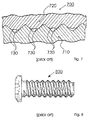
- Fig. 7 shows, in detail, a prior art jointed structure 700.
- a screw 710 having a known thread construction geometry is mating with a anchor material 720 assumed to have a low ductility.
- anchor material flows downwards the thread flanks building up eruptions 730.
- eruptions 720 of the low ductile anchor material 720 will crumble and tear, especially, in connections which are several times or periodically, respectively, unfastened during period of use, e.g. for purpose of service.
- chips and slivers are created.
- the plain bore hole is of the form generally considered as a 'through hole', such that the hole enters a cavity in the anchor casting, such a cavity being for the purpose of containing oil or other like liquids, or where the plain hole impinges in a zone containing electronic equipment, unit assembly malfunctions can occur together with a probability of lethal damage to the assembled unit.
- European patent 0 553 907 discloses a thread forming screw 800, which is depicted in Fig. 8, for cold forming internal threads in a work-piece comprised of a low ductility material, such as magnesium and the like.
- the screw uses primarily compressive forces to form the internal threads in the work-piece.
- the screw has a shank having an entering end and a head end. External threads are disposed on the shank.
- the external threads define a thread configuration with an angle measuring substantially within the range of 90° to 120°.
- a thread having a non-triangular thread profile with leading and trailing thread faces wherein at least one of said leading and trailing thread faces is provided with a convex curvature having a first radius has a tip of said non-triangular thread profile having also a convex curvature with a second radius wherein the value of the first radius is different from the value of the second radius.
- the first radius is larger than the second radius.
- a thread can be used in a thread-rolling screw or nut, in particular for materials having a low ductility, e.g. magnesium or an alloy composed thereof.
- the base or root, respectively, between two subsequent non-triangular thread profiles has a concave curvature with a third radius.
- the value of the third radius is smaller than the value of the first radius and preferably smaller than the value of the second radius.
- the transition from the at least one of the leading and trailing thread faces being provided with a convex curvature and the tip of the non-triangular thread profile is continuous.
- inventive thread forces are introduced into the mating component with a greater force component perpendicular to the mating component than conventional threads.
- the compressive strength of the low ductile material is greater than the shear strength, such materials can accept compressive forces more readily, and with less destructive effects, than a shearing force.
- the transition from the at least one of the leading and trailing thread faces being provided with a convex curvature and the base or bottom, respectively, between two consequent non-triangular thread profiles is continuous.
- leading and the trailing thread faces of a non-triangular thread profile are shaped symmetrically to each other.
- the leading and trailing thread faces of the non-triangular thread profiles are asymmetrically to each other.
- the pitch of the thread ranges preferably between 0.15 to 0.5 times the nominal diameter of the thread.
- a lobular cross-section screw read diameter as being the circumscribing circle of the lobular section.
- a screw and a nut for a threaded fastener system are provided.
- the screw or nut, respectively include a non-triangular external or internal thread, respectively, being designed according to the present invention.
- the screw of such fastener system comprises an external thread according to the invention and has a circular cross-sectional area or cross-section, respectively.
- the respective nut has an internal thread with a circular cross-sectional area.
- the threads of the screw have a non-circular, preferably a lobular cross-section, which is most preferably a trilobular cross-section. Due to the lobular cross-section design, there is a higher vibration resistance after having threaded the screw, respectively, being provided with the thread according to the invention into or onto the mating component.
- the screw may have a pilot section at the point of the screw for supporting easier insertion of the screw into a plain bore pilot hole of the component where the screw has to be screwed in.
- the length of the pilot section is preferably 2.0 times the pitch of the thread of the screw.
- the inventive nature of the screw thread profile provides for said profile to be preferably of non-triangular and/or non-trapezoidal form and to be of a defined and constructed arcuate form developed from at least two defined radii that are in accordance with the present invention.
- the at least two radii provide for the assembly conditions in accordance with the objective of the invention to be achieved.
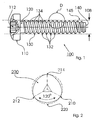
- FIG. 1 there is shown a schematic side elevation view of a thread-rolling screw 100 having a thread according to an embodiment of the present invention.
- the screw comprises a head 110 in which there is included a recess 112 that when said recess is engaged with an appropriate matching, driving tool, there can, via the driving tool, be imparted a rotational movement about the axis of the screw 109.
- This rotational movement in association with the helical scroll, as referenced below, provides the means by which the screw is driven into the plain bore pilot hole in the mating anchor material. (Not shown).
- the drive means used to impart rotational movement to the screw is not limited to a recess drive system. External drive systems would also be seen as appropriate.
- a screw body 120 Adjacent to the underside of the head of the screw and along the length of the screw, there is provided a screw body 120 on which is included a helical scroll or screw thread 130.
- Said scroll or screw thread is constructed such that the profile of the scroll has a geometry in accordance with the present invention and as described in detail further below and in respect of Fig. 3 together with the enlarged view of a part of the thread profile 130 contained within the circle D of Fig. 1.
- the thread entry zone being that which is the farthest removed from the head of the screw and designated 140, is provided with a piloting point for easy insertion and hole finding facility during the initial application of the screw.
- This piloting point encompasses in this particular embodiment two thread pitches 145. Thread pitch in this example being the distance between a selected point of one of the threads and the same point on an adjacent thread.
- the screw thread pitch is chosen to lie between 0.15 and 0.5 times the screw nominal outside diameter 108.
- a shank 120 which provides the enhanced thread profile 130 according to the present invention which will be described in more detail herein further below with respect to Fig. 3 together with the enlarged view of a part of the thread profile 130 contained within the circle D of Fig. 1.
- the thread profile 130 comprises thread tips 132 and thread base or roots 134, respectively.
- the screw 100 of Fig. 1 has on the opposite side of the head 110 a pilot end 140, which is adapted for easy insertion into a respective bore pilot hole of the respective application, which is not shown in Fig. 1.
- the pilot end 140 of the screw 100 comprises in this embodiment two turns or convolutions of the thread profile 130 corresponding to the length of two pitches of the screw 100, wherein the pitch is defined by the distance of two subsequent thread tips 132 or two subsequent thread roots 134, respectively.
- the dimension of the pitch of the thread is chosen from the range between 0.15 to 0.5 times the nominal diameter of the thread.
- the construction of the screw 100 having the thread configuration or profile 130 according to the present invention may have a lobular cross-section or any other form that is seen to be applicable for efficient forming of the internal thread during the assembly of the externally threaded screw 100.
- the outline of a typical lobular cross-section screw having lobes is shown in top view in Fig. 2.
- Fig. 2 is a schematic that shows a lobular form where there are three lobes 210, 212, 214 that are equally spaced around the periphery of the section.
- the number of lobes is not restricted to three as any odd number of lobes would be applicable for the purpose of supporting the objective of the fastener as and when used into magnesium alloy and other low ductile materials.
- the benefits of the lobular cross-section construction, for thread forming, self-tapping screws are clearly defined in the teachings of Phippard, jr. US Patent 3,195,156 , and subsequent international filings.
- the trilobular cross-section provides for better resistance against vibrations occurring in some applications, e.g. in automotive assembly, which have effect on the screw connection to become unscrewed.
- Fig. 2 illustrates a schematic plan view of the cross-section 200 of the screw 100 of Fig. 1 being a lobular cross-section.
- the screw 100 of Fig. 1 has three lobes 210, 212, 214 which are arranged substantially such that there is an angle of 120° between respective two lobes.
- screws having the shown cross-section are also known as trilobular screws.
- the broken circle 220 corresponds to the respective circumference of the trilobular cross-section.
- the trilobular cross-section provides for better resistance against vibrations occurring in some applications, e.g. in automotive assembly, which have effect on the screw connection to become unscrewed.
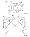
- FIG. 3 there the thread profile 300 of the screw 100 in Fig. 1 is shown in greater detail, which is depicted by the circle D in Fig. 1. There is a dashed line 310 corresponding to the symmetrical axis of the screw. Again, in Fig. 3 the enhanced thread profile 300 for use of the screw in materials having a low ductility can clearly be recognized. There are thread tips 342 and thread roots 344 which are connected by symmetrical thread faces 320 of the first embodiment of a screw according to the present invention. With respect to the moving direction, being depicted in Fig.
- FIG. 4 there is shown an enlarged cross-sectional view of one screw thread 400 of an external screw thread profile that is constructed according to the present invention, i.e. screw thread 400 corresponds to the thread profile 130 of the screw 100 in Fig. 1.
- the cross-section of the screw thread 400 is taken through two neighboring thread turns or convolutions, respectively, of the screw thread 400 formed on the outside of the screw.
- the thread pitch p is denoted as the distance between centers 460 and 462 of neighboring thread convolutions which is equivalent to the pitch definition as outlined above in conjunction with two subsequent thread tips.
- the depth of the thread TD is made between 0.4 to 0.65 times the pitch p of the thread.
- the thread profile of the screw thread 400 is developed from radii R that are designed such that the thread profile is symmetrical to the imaginary symmetry axis PA.
- the value of the radii R being the first radius of the inventive thread is made between 0.8 to 1.2 times the pitch p of the thread.
- the screw thread 400 has thread faces 420 extending away from the thread root 444 and terminate at the thread tip 442.
- the thread tip 442 forms a convex rounded transition between the thread surfaces 420 at the thread tip 442 being at least substantially convex.
- the rounded thread tips 442 are developed from a radius r1 forming the second radius of the inventive thread which is made substantially to 0.1 times the pitch p of the thread.
- the radius r1 is designed such that the rounded thread tips 442 are also symmetrical to the imaginary symmetry axis PA. That round thread tips 442 control and minimize advantageously shearing forces set up during cold forming of the complementary threads in the low ductility material.
- rounded thread roots 444 that form a concave rounded transition between subsequent thread surfaces 420.
- the rounded thread roots 444 are developed from a radius r2 forming the third radius of the inventive thread which is made substantially to 0.08 times the pitch p of the thread.
- the radius r2 is designed such that the rounded thread roots 444 are also symmetrical to the imaginary symmetry axis PA.
- the centers of the radii r1 and r2 are positioned on the symmetry axis of the thread tips 442 and the symmetry axis of the thread roots 444, respectively.
- the centers of the radii R defining the convex thread faces 420 are positioned such that there are fulfilled two conditions: first, in transition points from a thread tip 442 to a thread face 420 the tangent constructed on the circle having the radius R which defines the thread face 420 and the tangent constructed on the circle having the radius r1 which defines the thread tip 442 are substantially equal.
- transitions between the radii defining the thread tips 442, thread roots 444 and thread faces 420 of the inventive screw thread 400 is made such that the whole run of the thread profile is continuous. In other words, there are no sharp bends or breaks in the run of the thread profile.
- the radius form of the thread tip and the convex thread face profile form has the facility for developing internal forces, during the self-tapping of the mating thread in the anchor material, that are predominately compressive. This feature minimizes the magnitude of any shear forces that can be present with other thread profile designs. Subsequently, the destructive influences of induced shear forces in creating chips; burrs; slivers and the eruption of layers in the magnesium alloy nut anchor are eliminated.
- Fig. 5 is a schematic indicator of the direction of the forces that create the compression of the magnesium alloy material during the creation of the mating nut thread using self-tapping principles. It demonstrates the benefits that are achieved using the innovative profile construction of the present invention.
- This diagram further illustrates the development of the radius thread profile that enables a smooth arcuate thread construction to be continuous along the length of the threaded screw body or screw shank, respectively.
- This continuous arcuate construction being advantageous in overcoming nut material damage that would occur with interrupted contact surfaces.
- Fig.5 depicts one external thread 500 of the screw according to the first embodiment of the invention, which is used to cold form a mating thread in a component, as well as what are the forces acting on the material of the threads during the formation process which are shown as black arrows.
- a resultant force 505 acting upon the external and internal threads has a radial component 510 directed along a radius of the plain bore pilot hole formed in the component, and an axial component 520 directed along an axis of elongation of the screw. Following the curvature to the tip, the axial component 520 decreases and the compressing radius component 510 increases.
- Fig.6 is an illustration of a deviation that might occur in respect of the present invention as outlined. This deviation allows for the screw thread profile to be of a non-symmetrical form. However, it is clearly noted that the leading face of the profile is in accordance with all elements described in the present invention and that the trailing face is in a manner that provides a continuous arcuate form along the length of the threaded screw shank.
- FIG. 6 in comparison to Fig. 5, there is an example for an asymmetric thread configuration according to the present invention.
- Fig. 6 one external thread 600 of an embodiment of a screw is shown, wherein the convex trailing thread face 624 is much steeper then the convex leading thread face 622.
- the relatively magnitude of the radial component 610 of the resultant force 605 is reduced, the relatively magnitude of the axial component 620 of the resultant force 605 is increased.
- the axial component 620 acting upon the internal threads provides more pressure in direction of the bore pilot hole and screw, respectively.
- such a thread profile will be applicable in any application where higher clamping forces are needed and the ductility of the nut material allows it.
Landscapes
- Engineering & Computer Science (AREA)
- General Engineering & Computer Science (AREA)
- Mechanical Engineering (AREA)
- Physics & Mathematics (AREA)
- Geometry (AREA)
- Connection Of Plates (AREA)
- Transmission Devices (AREA)
- Surgical Instruments (AREA)
- Forging (AREA)
- Compositions Of Macromolecular Compounds (AREA)
- Curing Cements, Concrete, And Artificial Stone (AREA)
- Ceramic Products (AREA)
- Pressure Welding/Diffusion-Bonding (AREA)
- Dowels (AREA)
Claims (22)
- Gewinde, insbesondere für eine gewindefurchende oder selbstschneidende Schraube (100) bzw. Mutter, das ein nicht-dreieckiges Gewindeprofil (400) mit vorderen Gewindeflächen (422) und hinteren Gewindeflächen (424) aufweist, wobei wenigstens eine der vorderen Gewindeflächen (422) und hinteren Gewindeflächen (424) mit einer konvexen Krümmung versehen ist, die einen ersten Radius (R) aufweist,
dadurch gekennzeichnet, dass
die Spitze (442) des nicht-dreieckigen Gewindeprofils (400) ebenfalls eine konvexe Krümmung mit einem zweiten Radius (r1) aufweist, wobei der Wert des ersten Radius (R) verschieden ist vom Wert des zweiten Radius (r1). - Gewinde nach Anspruch 1,
wobei der erste Radius (R) größer ist als der zweite Radius (r1). - Gewinde nach einem der Ansprüche 1 oder 2,
wobei der Übergang zwischen der wenigstens einen der vorderen Gewindeflächen (422) und hinteren Gewindeflächen (424), die mit einer konvexen Krümmung versehen sind, und der Spitze (442) des nicht-dreieckigen Gewindeprofils (400) kontinuierlich ist. - Gewinde nach irgendeinem der Ansprüche 1 bis 3,
wobei der Fuß (444) zwischen zwei aufeinanderfolgenden nicht-dreieckigen Gewindeprofilen (400) eine konkave Krümmung mit einem dritten Radius (r2) aufweist. - Gewinde nach Anspruch 4,
wobei der Wert des dritten Radius (r2) kleiner ist als der Wert des ersten Radius (R) und vorzugsweise kleiner ist als der Wert des zweiten Radius (r1). - Gewinde nach Anspruch 4 oder 5,
wobei der Übergang zwischen der wenigstens einen der vorderen Gewindeflächen (422) und der hinteren Gewindeflächen (424), die mit einer konvexen Krümmung versehen sind, und dem Fuß (444) zwischen zwei aufeinanderfolgenden nicht-dreieckigen Gewindeprofilen (400) kontinuierlich ist. - Gewinde nach irgendeinem der Ansprüche 1 bis 6,
wobei die vorderen Gewindeflächen (422) und die hinteren Gewindeflächen (424) eines nicht-dreieckigen Gewindeprofils (400) symmetrisch zueinander geformt sind. - Gewinde nach irgendeinem der Ansprüche 1 bis 6,
wobei die vorderen Gewindeflächen (422) und die hinteren Gewindeflächen (424) eines nicht-dreieckigen Gewindeprofils (400) asymmetrisch zueinander geformt sind. - Gewinde nach irgendeinem der Ansprüche 1 bis 8,
wobei die Teilung (p) des Gewindes das 0,15-fache bis 0,5-fache des Nenndurchmessers des Gewindes beträgt. - Gewinde nach irgendeinem der Ansprüche 1 bis 9,
wobei der erste Radius (R) des Gewindeprofils (400) das 0,8-fache bis 1,2-fache der Teilung (p) des Gewindes beträgt. - Gewinde nach irgendeinem der Ansprüche 1 bis 10,
wobei die Tiefe (TD) des Gewindeprofils (400) das 0,4-fache bis 0,65-fache der Teilung (p) des Gewindes beträgt. - Gewinde nach irgendeinem der Ansprüche 1 bis 11,
wobei der zweite Radius (r1) der Gewindeprofile (400) durch das 0,1-fache der Teilung (p) des Gewindes definiert ist. - Gewinde nach irgendeinem der Ansprüche 1 bis 12,
wobei der dritte Radius (r2) des Gewindeprofils (400) durch das 0,08-fache der Teilung (p) des Gewindes definiert ist. - Schraube für ein Befestigungssystem,
wobei die Schraube (100) ein nicht-dreieckiges Außengewinde (130) enthält, das gemäß irgendeinem der Ansprüche 1 bis 13 gestartet ist. - Schraube nach Anspruch 14,
wobei die Schraube (100) eine gewindefurchende Schraube ist. - Schraube nach Anspruch 14 oder 15,
wobei das Außengewinde der Schraube einen kreisförmigen Querschnitt aufweist. - Schraube nach irgendeinem der Ansprüche 14 bis 16,
wobei das Außengewinde der Schraube (100) einen nicht-kreisförmigen, lappenförmigen Querschnitt (200) aufweist. - Schraube nach irgendeinem der Ansprüche 14 bis 17,
wobei das Außengewinde der Schraube (100) einen Zapfenabschnitt (145) an der Spitze (140) der Schraube (100) aufweist. - Schraube nach Anspruch 18,
wobei die Länge des Zapfenabschnitts (145) durch das 2,0-fache der Teilung (p) des Gewindes der Schraube (100) definiert ist. - Mutter für ein Befestigungssystem,
wobei die Mutter ein nicht-dreieckiges Innengewinde enthält, das gemäß irgendeinem der Ansprüche 1 bis 13 gestaltet ist. - Mutter nach Anspruch 20,
wobei die Mutter eine gewindefurchende Mutter ist. - Mutter nach Anspruch 20 oder 21,
wobei das Innengewinde der Mutter einen kreisförmigen Querschnitt aufweist.
Applications Claiming Priority (1)
| Application Number | Priority Date | Filing Date | Title |
|---|---|---|---|
| PCT/EP2003/001758 WO2004074698A1 (en) | 2003-02-20 | 2003-02-20 | Self-tapping screw for use in low ductile materials |
Publications (2)
| Publication Number | Publication Date |
|---|---|
| EP1601883A1 EP1601883A1 (de) | 2005-12-07 |
| EP1601883B1 true EP1601883B1 (de) | 2007-12-12 |
Family
ID=32892833
Family Applications (1)
| Application Number | Title | Priority Date | Filing Date |
|---|---|---|---|
| EP03815945A Expired - Lifetime EP1601883B1 (de) | 2003-02-20 | 2003-02-20 | Schneidschraube für die verwendung in gering dehnbaren materialien |
Country Status (9)
| Country | Link |
|---|---|
| US (1) | US20060263171A1 (de) |
| EP (1) | EP1601883B1 (de) |
| JP (1) | JP2006514236A (de) |
| CN (1) | CN100523526C (de) |
| AT (1) | ATE380944T1 (de) |
| AU (1) | AU2003215575A1 (de) |
| DE (1) | DE60318117T2 (de) |
| ES (1) | ES2297277T3 (de) |
| WO (1) | WO2004074698A1 (de) |
Families Citing this family (22)
| Publication number | Priority date | Publication date | Assignee | Title |
|---|---|---|---|---|
| DE102005024383B3 (de) * | 2005-05-27 | 2007-02-22 | Siemens Ag | Anordnung zur elektrischen Anbindung einer Magnesiumtragstruktur an ein Massepotential eines Kraftfahrzeugs |
| WO2009023168A2 (en) * | 2007-08-13 | 2009-02-19 | Research Engineering & Manufacturing, Inc. | Thread forming fastener |
| AU2007214341B8 (en) * | 2007-08-31 | 2015-02-19 | Sandvik Intellectual Property Ab | Rock Bolt |
| JP5204856B2 (ja) * | 2009-01-06 | 2013-06-05 | アルコア インコーポレイテッド | 改良されたナット及びボルト |
| US20110218580A1 (en) * | 2010-03-08 | 2011-09-08 | Stryker Trauma Sa | Bone fixation system with curved profile threads |
| ATE556665T1 (de) * | 2010-03-08 | 2012-05-15 | Stryker Trauma Sa | Systeme de fixation osseuse avec fils profiles incurves |
| KR100991015B1 (ko) * | 2010-04-22 | 2010-10-29 | 주식회사 아세아볼트 | 내충격, 내진동 및 체결력 강화 구조를 갖는 나사 및 나사식 기계요소 |
| JP5089740B2 (ja) * | 2010-08-23 | 2012-12-05 | 征人 菅野 | ねじ部材 |
| KR101680769B1 (ko) | 2010-10-22 | 2016-11-30 | 삼성전자주식회사 | 홀로그래피 기록/재생용 면광원 장치 |
| JP6228203B2 (ja) * | 2013-07-08 | 2017-11-08 | 株式会社トープラ | ねじ部品及びねじ部品の製造方法 |
| US10655669B2 (en) | 2013-11-26 | 2020-05-19 | Arconic Inc. | Advanced nut and bolt |
| EP3074647B1 (de) | 2013-11-26 | 2019-10-09 | Arconic Inc. | Erweitertes muttern- und schraubensystem |
| CN104074654B (zh) * | 2014-06-25 | 2017-11-03 | 中国第一汽车股份有限公司无锡油泵油嘴研究所 | 一种高压共轨系统喷油器联接螺纹结构 |
| DE102015111456A1 (de) * | 2015-07-15 | 2017-01-19 | Airbus Operations Gmbh | Schraube für eine elektrische Kontaktverbindung |
| DE102016103931A1 (de) * | 2016-03-04 | 2017-09-07 | Lisa Dräxlmaier GmbH | Schraube für Bauteile aus geschäumten Kunststoff |
| CN106837972A (zh) * | 2017-01-11 | 2017-06-13 | 中国科学院合肥物质科学研究院 | 一种双曲率半径牙底外螺纹 |
| CN111120487B (zh) * | 2018-10-31 | 2021-12-14 | 春雨工厂股份有限公司 | 螺栓 |
| US11313401B2 (en) * | 2018-10-31 | 2022-04-26 | Chun Yu Works & Co., Ltd. | Bolt |
| US11326637B2 (en) * | 2019-11-18 | 2022-05-10 | Semblex Corporation | Fasteners for high strength steel |
| CN112855709A (zh) * | 2021-02-08 | 2021-05-28 | 苏州新凯紧固系统有限公司 | 5g自导向调节螺钉 |
| DE102021131665B4 (de) * | 2021-12-01 | 2023-08-03 | Vibracoustic Se | Baugruppe mit Verschraubung |
| DE202024103005U1 (de) * | 2024-06-06 | 2025-09-12 | Igus Gmbh | Herstellungsoptimiertes Gewindebauteil |
Family Cites Families (26)
| Publication number | Priority date | Publication date | Assignee | Title |
|---|---|---|---|---|
| US3018685A (en) * | 1958-04-09 | 1962-01-30 | Admiral Corp | Sheet metal nut having depressed oval opening providing thread means |
| US3323402A (en) * | 1965-10-08 | 1967-06-06 | Standard Pressed Steel Co | Thread forms |
| US3394626A (en) * | 1967-03-17 | 1968-07-30 | Harold L. Oliver | Machine screw threads |
| US3527136A (en) * | 1969-02-27 | 1970-09-08 | Standard Pressed Steel Co | Self-retained thread rolling screw |
| US3985172A (en) * | 1971-06-17 | 1976-10-12 | General Motors Corporation | Panel extruding nut and assembly |
| CH535391A (de) * | 1971-07-20 | 1973-03-31 | Brander Hans | Verfahren zur Herstellung von Dehnschäften an bolzenartigen Verbindungselementen |
| US3965793A (en) * | 1971-12-08 | 1976-06-29 | Keystone Consolidated Industries, Inc. | Particleboard screw |
| US3971086A (en) * | 1974-02-14 | 1976-07-27 | Textron, Inc. | Method of fabricating a fastener assembly |
| US4161132A (en) * | 1975-06-05 | 1979-07-17 | Bulten-Kanthal Aktiebolog | Self-tapping screw |
| US4069730A (en) * | 1976-06-03 | 1978-01-24 | Wales-Beech Corporation | Thread-forming screw |
| GB2104997A (en) * | 1981-06-06 | 1983-03-16 | Gkn Mills Building Serv | Builders scaffolding |
| GB2110336B (en) * | 1981-12-02 | 1985-11-06 | Marlow Mfg | Threaded scaffolding members |
| DE3207975A1 (de) * | 1982-03-05 | 1983-09-15 | Richard Bergner GmbH & Co, 8540 Schwabach | Gewindeselbstformende schraube |
| US4526053A (en) * | 1983-02-14 | 1985-07-02 | Millipore Corporation | Stabilized apparatus for converting rotational motion to linear motion |
| US4549754A (en) * | 1983-06-20 | 1985-10-29 | Reed Tubular Products Company | Tool joint |
| US4534690A (en) * | 1983-10-26 | 1985-08-13 | Illinois Tool Works Inc. | Assymetrically shaped thread forming screw and method of making same |
| FR2624931B1 (fr) * | 1987-12-18 | 1990-06-01 | Simmonds Sa | Element filete perfectionne formant par exemple une vis, et assemblage de pieces realise a l'aide de cet element |
| US5340254A (en) * | 1992-01-31 | 1994-08-23 | Textron Inc. | Thread forming screw for forming an internal thread in a low ductility material |
| US5385439A (en) * | 1993-11-29 | 1995-01-31 | Hurdle; Donald R. | Radial extrusion thread-forming screw |
| US5722808A (en) * | 1996-09-11 | 1998-03-03 | Conti Fasteners Ag | Threaded fastener system |
| US6062786A (en) * | 1998-11-13 | 2000-05-16 | Garver; Michael A. | Anti-cross treading fastener lead-in point |
| US6089806A (en) * | 1999-01-25 | 2000-07-18 | Conti Fasteners | Blank for self-tapping fastener |
| WO2001001000A1 (en) * | 1999-06-28 | 2001-01-04 | Aoyama Seisakusho Co., Ltd. | Tapping screw |
| US6375401B1 (en) * | 1999-10-20 | 2002-04-23 | Continental/Midland, Inc. | Fastener shank crossection utilizing non-circular constant breadth curves |
| JP2002213425A (ja) * | 2000-11-14 | 2002-07-31 | Meidoo:Kk | ボルト |
| US6494655B1 (en) * | 2001-09-13 | 2002-12-17 | Conti Fasteners Ag | Self-tapping screw and method for joining thin workpieces |
-
2003
- 2003-02-20 JP JP2004568386A patent/JP2006514236A/ja active Pending
- 2003-02-20 ES ES03815945T patent/ES2297277T3/es not_active Expired - Lifetime
- 2003-02-20 AU AU2003215575A patent/AU2003215575A1/en not_active Abandoned
- 2003-02-20 US US10/546,443 patent/US20060263171A1/en not_active Abandoned
- 2003-02-20 EP EP03815945A patent/EP1601883B1/de not_active Expired - Lifetime
- 2003-02-20 WO PCT/EP2003/001758 patent/WO2004074698A1/en not_active Ceased
- 2003-02-20 DE DE60318117T patent/DE60318117T2/de not_active Expired - Lifetime
- 2003-02-20 AT AT03815945T patent/ATE380944T1/de not_active IP Right Cessation
- 2003-02-20 CN CN03826288.6A patent/CN100523526C/zh not_active Expired - Lifetime
Also Published As
| Publication number | Publication date |
|---|---|
| WO2004074698A1 (en) | 2004-09-02 |
| ES2297277T3 (es) | 2008-05-01 |
| CN1764790A (zh) | 2006-04-26 |
| DE60318117D1 (de) | 2008-01-24 |
| ATE380944T1 (de) | 2007-12-15 |
| DE60318117T2 (de) | 2008-12-11 |
| JP2006514236A (ja) | 2006-04-27 |
| EP1601883A1 (de) | 2005-12-07 |
| AU2003215575A1 (en) | 2004-09-09 |
| CN100523526C (zh) | 2009-08-05 |
| US20060263171A1 (en) | 2006-11-23 |
Similar Documents
| Publication | Publication Date | Title |
|---|---|---|
| US20060263171A1 (en) | Self-tapping screw for use in low ductile materials | |
| US8506227B2 (en) | Thread forming screw thread and corresponding thread roll die | |
| EP0859916B1 (de) | Befestigungssystem mit schrauben | |
| EP2396561B1 (de) | Gewindeschneidschraube und entsprechende gewindewalzbacke | |
| EP0476831B1 (de) | Gewindeschneidende Schraube | |
| US4799844A (en) | Elliptical thread design | |
| EP2302224B1 (de) | Anzugsstruktur mit hochfesten selbstformenden schrauben | |
| EP2700829B1 (de) | Schneidschraube | |
| US7665942B2 (en) | Nail with multiple shank deformations | |
| US20040033122A1 (en) | Tapping assist fastening element and method | |
| EP2016298B1 (de) | Stanzmutter und verwendung dafür | |
| US6494655B1 (en) | Self-tapping screw and method for joining thin workpieces | |
| US20070280803A1 (en) | All-metal thread locking/prevailing torque threaded fastener | |
| CA2277535C (en) | Thread forming pipe plug | |
| KR20050111744A (ko) | 저유연성 재료에서 사용될 수 있는 나사골 제작용 나사 | |
| WO2010093330A1 (en) | Torque retention screw thread fastener and corresponding thread roll die | |
| EP4686842A1 (de) | Selbstbohrendes, selbstschneidendes befestigungselement | |
| JP7667977B2 (ja) | ブラインドファスナー | |
| MXPA98003450A (en) | Threaded fastener system |
Legal Events
| Date | Code | Title | Description |
|---|---|---|---|
| PUAI | Public reference made under article 153(3) epc to a published international application that has entered the european phase |
Free format text: ORIGINAL CODE: 0009012 |
|
| 17P | Request for examination filed |
Effective date: 20050920 |
|
| AK | Designated contracting states |
Kind code of ref document: A1 Designated state(s): AT BE BG CH CY CZ DE DK EE ES FI FR GB GR HU IE IT LI LU MC NL PT SE SI SK TR |
|
| AX | Request for extension of the european patent |
Extension state: AL LT LV MK RO |
|
| DAX | Request for extension of the european patent (deleted) | ||
| GRAP | Despatch of communication of intention to grant a patent |
Free format text: ORIGINAL CODE: EPIDOSNIGR1 |
|
| GRAS | Grant fee paid |
Free format text: ORIGINAL CODE: EPIDOSNIGR3 |
|
| GRAA | (expected) grant |
Free format text: ORIGINAL CODE: 0009210 |
|
| AK | Designated contracting states |
Kind code of ref document: B1 Designated state(s): AT BE BG CH CY CZ DE DK EE ES FI FR GB GR HU IE IT LI LU MC NL PT SE SI SK TR |
|
| REG | Reference to a national code |
Ref country code: GB Ref legal event code: FG4D |
|
| REG | Reference to a national code |
Ref country code: CH Ref legal event code: EP |
|
| REG | Reference to a national code |
Ref country code: IE Ref legal event code: FG4D |
|
| REF | Corresponds to: |
Ref document number: 60318117 Country of ref document: DE Date of ref document: 20080124 Kind code of ref document: P |
|
| REG | Reference to a national code |
Ref country code: CH Ref legal event code: NV Representative=s name: E. BLUM & CO. AG PATENT- UND MARKENANWAELTE VSP |
|
| REG | Reference to a national code |
Ref country code: SE Ref legal event code: TRGR |
|
| REG | Reference to a national code |
Ref country code: ES Ref legal event code: FG2A Ref document number: 2297277 Country of ref document: ES Kind code of ref document: T3 |
|
| PG25 | Lapsed in a contracting state [announced via postgrant information from national office to epo] |
Ref country code: SI Free format text: LAPSE BECAUSE OF FAILURE TO SUBMIT A TRANSLATION OF THE DESCRIPTION OR TO PAY THE FEE WITHIN THE PRESCRIBED TIME-LIMIT Effective date: 20071212 Ref country code: FI Free format text: LAPSE BECAUSE OF FAILURE TO SUBMIT A TRANSLATION OF THE DESCRIPTION OR TO PAY THE FEE WITHIN THE PRESCRIBED TIME-LIMIT Effective date: 20071212 |
|
| ET | Fr: translation filed | ||
| PG25 | Lapsed in a contracting state [announced via postgrant information from national office to epo] |
Ref country code: PT Free format text: LAPSE BECAUSE OF FAILURE TO SUBMIT A TRANSLATION OF THE DESCRIPTION OR TO PAY THE FEE WITHIN THE PRESCRIBED TIME-LIMIT Effective date: 20080512 |
|
| PLBE | No opposition filed within time limit |
Free format text: ORIGINAL CODE: 0009261 |
|
| STAA | Information on the status of an ep patent application or granted ep patent |
Free format text: STATUS: NO OPPOSITION FILED WITHIN TIME LIMIT |
|
| PG25 | Lapsed in a contracting state [announced via postgrant information from national office to epo] |
Ref country code: MC Free format text: LAPSE BECAUSE OF NON-PAYMENT OF DUE FEES Effective date: 20080228 Ref country code: DK Free format text: LAPSE BECAUSE OF FAILURE TO SUBMIT A TRANSLATION OF THE DESCRIPTION OR TO PAY THE FEE WITHIN THE PRESCRIBED TIME-LIMIT Effective date: 20071212 |
|
| 26N | No opposition filed |
Effective date: 20080915 |
|
| PG25 | Lapsed in a contracting state [announced via postgrant information from national office to epo] |
Ref country code: IE Free format text: LAPSE BECAUSE OF NON-PAYMENT OF DUE FEES Effective date: 20080220 Ref country code: GR Free format text: LAPSE BECAUSE OF FAILURE TO SUBMIT A TRANSLATION OF THE DESCRIPTION OR TO PAY THE FEE WITHIN THE PRESCRIBED TIME-LIMIT Effective date: 20080313 Ref country code: EE Free format text: LAPSE BECAUSE OF FAILURE TO SUBMIT A TRANSLATION OF THE DESCRIPTION OR TO PAY THE FEE WITHIN THE PRESCRIBED TIME-LIMIT Effective date: 20071212 |
|
| PG25 | Lapsed in a contracting state [announced via postgrant information from national office to epo] |
Ref country code: BG Free format text: LAPSE BECAUSE OF FAILURE TO SUBMIT A TRANSLATION OF THE DESCRIPTION OR TO PAY THE FEE WITHIN THE PRESCRIBED TIME-LIMIT Effective date: 20080312 |
|
| PGFP | Annual fee paid to national office [announced via postgrant information from national office to epo] |
Ref country code: AT Payment date: 20090219 Year of fee payment: 7 Ref country code: ES Payment date: 20090225 Year of fee payment: 7 |
|
| PGFP | Annual fee paid to national office [announced via postgrant information from national office to epo] |
Ref country code: NL Payment date: 20090223 Year of fee payment: 7 Ref country code: SK Payment date: 20090216 Year of fee payment: 7 |
|
| PGFP | Annual fee paid to national office [announced via postgrant information from national office to epo] |
Ref country code: GB Payment date: 20090223 Year of fee payment: 7 |
|
| PG25 | Lapsed in a contracting state [announced via postgrant information from national office to epo] |
Ref country code: CY Free format text: LAPSE BECAUSE OF FAILURE TO SUBMIT A TRANSLATION OF THE DESCRIPTION OR TO PAY THE FEE WITHIN THE PRESCRIBED TIME-LIMIT Effective date: 20071212 |
|
| PGFP | Annual fee paid to national office [announced via postgrant information from national office to epo] |
Ref country code: BE Payment date: 20090224 Year of fee payment: 7 |
|
| PGFP | Annual fee paid to national office [announced via postgrant information from national office to epo] |
Ref country code: SE Payment date: 20090223 Year of fee payment: 7 |
|
| PG25 | Lapsed in a contracting state [announced via postgrant information from national office to epo] |
Ref country code: HU Free format text: LAPSE BECAUSE OF FAILURE TO SUBMIT A TRANSLATION OF THE DESCRIPTION OR TO PAY THE FEE WITHIN THE PRESCRIBED TIME-LIMIT Effective date: 20080613 Ref country code: LU Free format text: LAPSE BECAUSE OF NON-PAYMENT OF DUE FEES Effective date: 20080220 |
|
| BERE | Be: lapsed |
Owner name: CONTI FASTENERS A.G. Effective date: 20100228 |
|
| REG | Reference to a national code |
Ref country code: NL Ref legal event code: V1 Effective date: 20100901 |
|
| EUG | Se: european patent has lapsed | ||
| GBPC | Gb: european patent ceased through non-payment of renewal fee |
Effective date: 20100220 |
|
| REG | Reference to a national code |
Ref country code: SK Ref legal event code: MM4A Ref document number: E 3047 Country of ref document: SK Effective date: 20100220 |
|
| PG25 | Lapsed in a contracting state [announced via postgrant information from national office to epo] |
Ref country code: SK Free format text: LAPSE BECAUSE OF NON-PAYMENT OF DUE FEES Effective date: 20100220 Ref country code: AT Free format text: LAPSE BECAUSE OF NON-PAYMENT OF DUE FEES Effective date: 20100220 |
|
| PG25 | Lapsed in a contracting state [announced via postgrant information from national office to epo] |
Ref country code: NL Free format text: LAPSE BECAUSE OF NON-PAYMENT OF DUE FEES Effective date: 20100901 |
|
| PG25 | Lapsed in a contracting state [announced via postgrant information from national office to epo] |
Ref country code: BE Free format text: LAPSE BECAUSE OF NON-PAYMENT OF DUE FEES Effective date: 20100228 |
|
| REG | Reference to a national code |
Ref country code: ES Ref legal event code: FD2A Effective date: 20110309 |
|
| PG25 | Lapsed in a contracting state [announced via postgrant information from national office to epo] |
Ref country code: GB Free format text: LAPSE BECAUSE OF NON-PAYMENT OF DUE FEES Effective date: 20100220 |
|
| PG25 | Lapsed in a contracting state [announced via postgrant information from national office to epo] |
Ref country code: ES Free format text: LAPSE BECAUSE OF NON-PAYMENT OF DUE FEES Effective date: 20110308 |
|
| PG25 | Lapsed in a contracting state [announced via postgrant information from national office to epo] |
Ref country code: ES Free format text: LAPSE BECAUSE OF NON-PAYMENT OF DUE FEES Effective date: 20100221 |
|
| PG25 | Lapsed in a contracting state [announced via postgrant information from national office to epo] |
Ref country code: SE Free format text: LAPSE BECAUSE OF NON-PAYMENT OF DUE FEES Effective date: 20100221 |
|
| REG | Reference to a national code |
Ref country code: FR Ref legal event code: PLFP Year of fee payment: 14 |
|
| REG | Reference to a national code |
Ref country code: FR Ref legal event code: PLFP Year of fee payment: 15 |
|
| REG | Reference to a national code |
Ref country code: FR Ref legal event code: PLFP Year of fee payment: 16 |
|
| PGFP | Annual fee paid to national office [announced via postgrant information from national office to epo] |
Ref country code: DE Payment date: 20220307 Year of fee payment: 20 Ref country code: CH Payment date: 20220221 Year of fee payment: 20 |
|
| PGFP | Annual fee paid to national office [announced via postgrant information from national office to epo] |
Ref country code: TR Payment date: 20220208 Year of fee payment: 20 Ref country code: IT Payment date: 20220228 Year of fee payment: 20 Ref country code: FR Payment date: 20220221 Year of fee payment: 20 Ref country code: CZ Payment date: 20220211 Year of fee payment: 20 |
|
| REG | Reference to a national code |
Ref country code: DE Ref legal event code: R071 Ref document number: 60318117 Country of ref document: DE |
|
| REG | Reference to a national code |
Ref country code: CH Ref legal event code: PL |
|
| PG25 | Lapsed in a contracting state [announced via postgrant information from national office to epo] |
Ref country code: CZ Free format text: LAPSE BECAUSE OF EXPIRATION OF PROTECTION Effective date: 20230220 |