EP1601901B1 - Füllventil für toilettenspülkasten - Google Patents
Füllventil für toilettenspülkasten Download PDFInfo
- Publication number
- EP1601901B1 EP1601901B1 EP04718360A EP04718360A EP1601901B1 EP 1601901 B1 EP1601901 B1 EP 1601901B1 EP 04718360 A EP04718360 A EP 04718360A EP 04718360 A EP04718360 A EP 04718360A EP 1601901 B1 EP1601901 B1 EP 1601901B1
- Authority
- EP
- European Patent Office
- Prior art keywords
- valve
- pintle
- chamber
- inlet
- diaphragm
- Prior art date
- Legal status (The legal status is an assumption and is not a legal conclusion. Google has not performed a legal analysis and makes no representation as to the accuracy of the status listed.)
- Expired - Lifetime
Links
- 239000000463 material Substances 0.000 claims description 4
- 239000002184 metal Substances 0.000 claims description 3
- 239000004033 plastic Substances 0.000 claims description 3
- 229920003023 plastic Polymers 0.000 claims description 3
- 239000012858 resilient material Substances 0.000 claims description 3
- 239000002131 composite material Substances 0.000 claims description 2
- 229910001220 stainless steel Inorganic materials 0.000 claims description 2
- 239000010935 stainless steel Substances 0.000 claims description 2
- XLYOFNOQVPJJNP-UHFFFAOYSA-N water Substances O XLYOFNOQVPJJNP-UHFFFAOYSA-N 0.000 abstract description 16
- 238000007789 sealing Methods 0.000 description 4
- 238000011010 flushing procedure Methods 0.000 description 3
- 230000006835 compression Effects 0.000 description 2
- 238000007906 compression Methods 0.000 description 2
- 230000000694 effects Effects 0.000 description 2
- 238000001125 extrusion Methods 0.000 description 2
- 230000003213 activating effect Effects 0.000 description 1
- 230000015572 biosynthetic process Effects 0.000 description 1
- 230000000740 bleeding effect Effects 0.000 description 1
- 238000010276 construction Methods 0.000 description 1
- 238000007599 discharging Methods 0.000 description 1
- 238000005755 formation reaction Methods 0.000 description 1
- 239000002991 molded plastic Substances 0.000 description 1
- 230000002093 peripheral effect Effects 0.000 description 1
Images


Classifications
-
- F—MECHANICAL ENGINEERING; LIGHTING; HEATING; WEAPONS; BLASTING
- F16—ENGINEERING ELEMENTS AND UNITS; GENERAL MEASURES FOR PRODUCING AND MAINTAINING EFFECTIVE FUNCTIONING OF MACHINES OR INSTALLATIONS; THERMAL INSULATION IN GENERAL
- F16K—VALVES; TAPS; COCKS; ACTUATING-FLOATS; DEVICES FOR VENTING OR AERATING
- F16K31/00—Actuating devices; Operating means; Releasing devices
- F16K31/12—Actuating devices; Operating means; Releasing devices actuated by fluid
- F16K31/36—Actuating devices; Operating means; Releasing devices actuated by fluid in which fluid from the circuit is constantly supplied to the fluid motor
- F16K31/38—Actuating devices; Operating means; Releasing devices actuated by fluid in which fluid from the circuit is constantly supplied to the fluid motor in which the fluid works directly on both sides of the fluid motor, one side being connected by means of a restricted passage and the motor being actuated by operating a discharge from that side
- F16K31/385—Actuating devices; Operating means; Releasing devices actuated by fluid in which fluid from the circuit is constantly supplied to the fluid motor in which the fluid works directly on both sides of the fluid motor, one side being connected by means of a restricted passage and the motor being actuated by operating a discharge from that side the fluid acting on a diaphragm
-
- F—MECHANICAL ENGINEERING; LIGHTING; HEATING; WEAPONS; BLASTING
- F16—ENGINEERING ELEMENTS AND UNITS; GENERAL MEASURES FOR PRODUCING AND MAINTAINING EFFECTIVE FUNCTIONING OF MACHINES OR INSTALLATIONS; THERMAL INSULATION IN GENERAL
- F16K—VALVES; TAPS; COCKS; ACTUATING-FLOATS; DEVICES FOR VENTING OR AERATING
- F16K31/00—Actuating devices; Operating means; Releasing devices
- F16K31/12—Actuating devices; Operating means; Releasing devices actuated by fluid
- F16K31/18—Actuating devices; Operating means; Releasing devices actuated by fluid actuated by a float
- F16K31/34—Actuating devices; Operating means; Releasing devices actuated by fluid actuated by a float acting on pilot valve controlling the cut-off apparatus
-
- Y—GENERAL TAGGING OF NEW TECHNOLOGICAL DEVELOPMENTS; GENERAL TAGGING OF CROSS-SECTIONAL TECHNOLOGIES SPANNING OVER SEVERAL SECTIONS OF THE IPC; TECHNICAL SUBJECTS COVERED BY FORMER USPC CROSS-REFERENCE ART COLLECTIONS [XRACs] AND DIGESTS
- Y10—TECHNICAL SUBJECTS COVERED BY FORMER USPC
- Y10T—TECHNICAL SUBJECTS COVERED BY FORMER US CLASSIFICATION
- Y10T137/00—Fluid handling
- Y10T137/7287—Liquid level responsive or maintaining systems
- Y10T137/7358—By float controlled valve
- Y10T137/7368—Servo relay operation of control
- Y10T137/7371—Fluid pressure
- Y10T137/7374—Flexible diaphragm valve
Definitions
- This invention relates to filling valves for toilet cisterns and more particularly to automatically closing valves.
- Toilet filling valves which operate to close against pressure under the influence of a float mounted on a lever arm are widely used. They are however subject to leakage and consequently it is desirable to have such a valve which is pressure assisted.
- GB 1 532 210 describes such a toilet filling valve and corresponds to the preamble of claim 1.
- GB 1 532 210 describes a pressure assisted valve having an inlet into a chamber and an outlet from the chamber, wherein the inlet and outlet open adjacent each other into the chamber separated by a seal face for a diaphragm closure member in the chamber, with an axially movable pintle located through the diaphragm, a chamber vent opening from the chamber closable by an enlarged end to the pintle, a control spindle extending from the enlarged end of the pintle through the chamber vent opening, at least one bleed passage past the pintle into the chamber, and a manipulating mechanism at the spindle end to move the pintle to open the chamber vent opening.
- a further feature of the invention provides for the outlet to be formed around the inlet.
- the characterizing feature of this invention provides for the pintle to be a composite structure of plastic material with a metal spindle.
- a further feature of this invention provides for the manipulating mechanism to be an arm pivoted at one end and having depending from the other a combination float and anti-float assembly, the assembly being adjustable in height relative to the valve and guided on a cistern filling pipe.
- the metal spindle having one end embedded in the plastic material, for the bleed passage to be provided by ribs located around and extending along the pintle slidable through the diaphragm and for the ribs to act as a filter.
- the invention also provides for the pintle to be supported by a perforated guide in the valve inlet, for the guide to be resiliently biased to close the enlarged end of the pintle against the chamber vent opening and for the enlarged end to form a tapered plug.
- chamber vent opening to be lined with resilient material and for the diaphragm to have an annular ring of increased flexibility adjacent its outer periphery.
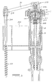
- a toilet cistern filling valve (1) consists of a body (2) having an inlet (3) and an annular outlet (4) around the inlet (3) into a cistern (not shown).
- the inlet (3) extends from the side of the valve (1) and has an upward bend (5) to open into a chamber (6).
- the inlet (3) has a screw threaded connection (7) to enable the valve (1) to be secured to extend through the cistern wall for connection into a water supply under pressure.
- the chamber (6) has an annular outlet opening (8) concentric around the inlet opening (9).
- the inlet opening (9) and outlet opening (8) are separated by a tubular extrusion (10), the top end of which forms an annular seal face (11).
- the face (11) is engageable by a diaphragm closure member (12) to control flow between the openings (8) and (9).
- the chamber (6) has a top (13) which is made as a closure which secures the peripheral portion (14) of the diaphragm (12) in position in sealing engagement.
- This engagement can conveniently be effected by a rigid ring (15) inserted above the diaphragm (12) to be clamped in position by the top (13).
- the top (13) has a central vent opening (16) which is lined with resilient material in the form of a resilient seal (17) located around the vent opening (16) between the top (13) and the ring (15).
- the ring (15) supports the resilient seal (17).
- the top (13) is secured to the body (2) by bayonet type engaging formations, however any other suitable arrangement for engagement of these components (13) and (2) can be provided.
- annular thin section (18) provides increased flexibility adjacent its periphery. This enables the central part to move easily into and out of the closure position on the face (11) located between the inlet opening (9) and annular outlet opening (8).
- the central part of the diaphragm (12) is tapered downwardly into the inlet opening (9) and a preferably moulded plastics material pintle (19) extends through the center of the diaphragm (12).
- the upper end of the pintle (19) is operatively located within the chamber (6) and has an enlargement on its end in the form of a tapered plug (20).
- This plug (20) engages in the resilient seal (17) to close the vent opening (16) from the chamber (6).
- a preferably stainless steel operating spindle (21) is embedded in the pintle (19) to extend through the vent opening (16) where the free end (22) is located in a recess provided in a slide (23).
- the slide (23) is supported in an extension (24) from the top (13) of the chamber (6).
- the upper face of slide (23) is exposed and can be engaged by a suitable manipulating mechanism indicated at (25).
- the lower end of the pintle (19) is secured to a slidable guide (27) that is located in the inlet (3) to the body (2).
- This guide (27) is perforated to allow water to flow through the valve (1) and is also resiliently biased by a compression spring (28) to assist the closure of the plug (20) against the seal (17).
- a bleed passage indicated at (29) providing for a bleed flow from the inlet (3) into the chamber (6) above the diaphragm (12).
- This passage (29) between the pintle (19) and the diaphragm (12) is provided by ribs located around and extending along the pintle (19) which slides in the diaphragm (12). The ribs act as a filter to prevent debris entrained in the inlet water supply from entering the chamber (6). This in turn ensures that the passageway that opens during operation of the valve (1), between the tapered plug (20) and the seal (17), will not become filled with obstructing debris.
- the manipulating mechanism (25) and consequently the operation of the filling valve (1) is activated by the influence of the rise and fall of the water level in the cistern on a combination float and anti-float assembly (30) such that when the cistern flushing valve is opened the filling valve (1) will open.
- the flushing valve (not shown) closes automatically after discharge of water and the filling valve (1) closes after the cistern has been filled as required.
- FIG. 1 illustrates the operating means for the valve (1) of Figure 1.
- An arm (31) is pivoted to a projection (32) from the top (13) adjacent the exposed face of slide (23).
- the arm (31) is shaped so that pivoting thereof in an operatively downward direction will depress the slide (23) and consequently the tapered plug (20) to open the vent opening (16) from the chamber (6).
- the free end (33) of the arm (31) has a downwardly depending rod (34) screw threaded at its lower end (35). This end (35) engages the combination float and anti-float assembly (30) in a manner enabling the position of assembly (30) to be adjustable within the toilet cistern.
- the assembly (30) can conveniently be guided for movement on a cistern filling pipe (36) discharging into the lower part of the cistern in conventional manner.
- valve (1) shown in Figure 3 is substantially the same as that of Figure 1. Both Figures are accordingly labeled with the same reference numerals. The main difference is that the valve (1) in Figure 3 is adapted for mounting directly above the filling pipe (36). This valve (1) also has a union nut (26) which engages with threads on the body (2) to secure the top (13) in position.
- flushing of the cistern causes automatic opening of the inlet valve (1).
- Figure 5 shows a valve (1) with a bottom type inlet (3) but otherwise substantially the same as those already described.
- the inlet (3) is straight and extends upwardly from the bottom of the cistern.
- the inlet (3) similarly opens into the chamber (6).
- the length of the inlet (3) from the bottom of the cistern is of a smaller diameter than an upper portion (37) spaced apart from the seal face (11).
- the enlarged portion (37) of the inlet (3) houses the slidable guide (27).
- An annular shoulder is provided at the lower end of the portion (37) against which the compression spring (28) seats.
- the upper region of the portion (37) forms the tubular extrusion (10).
- This embodiment allows for the float and anti-float assembly (30) to be guided for movement on the inlet pipe as shown.
Landscapes
- Engineering & Computer Science (AREA)
- General Engineering & Computer Science (AREA)
- Mechanical Engineering (AREA)
- Self-Closing Valves And Venting Or Aerating Valves (AREA)
- Sanitary Device For Flush Toilet (AREA)
- Lift Valve (AREA)
- Check Valves (AREA)
- Filling Of Jars Or Cans And Processes For Cleaning And Sealing Jars (AREA)
Claims (13)
- Druckunterstütztes Ventil (1), mit einem Einlass (3) in eine Kammer (6) und einen Auslass (4) aus der Kammer, wobei der Einlass (3) und der Auslass (4) nebeneinander in die Kammer (6) münden und durch eine Dichtungsfläche (11) für ein in der Kammer (6) vorhandenes Membranverschlusselement (12) getrennt sind, einem axial beweglichen Zapfen (19), der durch die Membran (12) verlaufend angeordnet ist, einer Kammerentlüftungsöffnung (16) aus der Kammer (6), die durch ein erweitertes Ende (20) des Zapfens (19) verschließbar ist, einer Steuerspindel (21), die sich von dem erweiterten Ende (20) des Zapfens (19) durch die Kammerentlüftungsöffnung (16) erstreckt, wenigstens einem zwischen dem Zapfen (19) und der Membran (12) angeordneten Entleerungsdurchlass (29) in die Kammer (6) und einem Betätigungsmechanismus (25) an dem Ende der Spindel (21), um den Zapfen (19) zu bewegen, um die Kammerentlüftungsöffnung (16) zu öffnen, dadurch gekennzeichnet, dass der Zapfen (19) und die Spindel (21) aus einer Verbundstruktur bestehen, wobei der Zapfen (19) aus Kunststoff besteht und die Spindel (21) aus Metall besteht.
- Ventil (1) nach Anspruch 1, bei dem ein Ende der Spindel (21) in das erweiterte Ende (20) des Zapfens (19) eingebettet ist.
- Ventil (1) nach Anspruch 1 oder Anspruch 2, bei dem die Spindel (21) rostfreier Stahl ist.
- Ventil (1) nach einem der vorhergehenden Ansprüche, bei dem der Auslass (4) um den Einlass (3) ausgebildet ist.
- Ventil (1) nach einem der vorhergehenden Ansprüche, bei dem der Betätigungsmechanismus (25) ein Arm (31) ist, der an einem Ende an dem Ventil (1) angelenkt ist und sich von dem Zapfen erstreckt, um mit dem freien Ende (22) der Spindel (21) in Eingriff zu gelangen, und mit einer von dem anderen Ende (33) herabhängende kombinierte Schwimmer- und Antischwimmer-Baugruppe (30) versehen ist.
- Ventil (1) nach Anspruch 5, bei dem der Arm mit der Spindel (21) über einen Gleiter (22) in Eingriff ist, der in einer Verlängerung (24) des Ventils (1) unterstützt ist.
- Ventil (1) nach Anspruch 6, bei dem die Höhe der Baugruppe (30) in Bezug auf das Ende (33) des Arms (31) einstellbar ist und an einem Zisternenbefüllungsrohr (36) geführt ist.
- Ventil (1) nach einem der vorhergehenden Ansprüche, bei dem der Entleerungsdurchlass (29) durch Rippen vorgesehen ist, die sich um den Zapfen (19), der durch die Membran (12) gleiten kann, befinden und erstrecken.
- Ventil (1) nach Anspruch 8, bei dem die Rippen als ein Filter wirken.
- Ventil (1) nach einem der vorhergehenden Ansprüche, bei dem der Zapfen (19) durch eine durchlochte Führung (27) in dem Einlass (3) des Ventils (1) unterstützt ist, die elastisch vorbelastet ist, um das erweiterte Ende (20) des Zapfens (19) gegen die Kammerentlüftungsöffnung (16) zu schließen.
- Ventil (1) nach einem der vorhergehenden Ansprüche, bei dem das erweiterte Ende des Zapfens (19) einen konisch zulaufenden Stopfen (20) bildet.
- Ventil (1) nach einem der vorhergehenden Ansprüche, bei dem die Kammerentlüftungsöffnung (16) mit einem elastischen Werkstoff ausgekleidet ist.
- Ventil (1) nach einem der vorhergehenden Ansprüche, bei dem die Membran einen Kreisring mit erhöhter Flexibilität in der Nähe ihres äußeren Umfangs besitzt.
Applications Claiming Priority (3)
| Application Number | Priority Date | Filing Date | Title |
|---|---|---|---|
| ZA200301926 | 2003-03-10 | ||
| ZA200301926 | 2003-03-10 | ||
| PCT/IB2004/000621 WO2004081435A1 (en) | 2003-03-10 | 2004-03-08 | Toilet cistern filling valve |
Publications (2)
| Publication Number | Publication Date |
|---|---|
| EP1601901A1 EP1601901A1 (de) | 2005-12-07 |
| EP1601901B1 true EP1601901B1 (de) | 2006-06-21 |
Family
ID=32991529
Family Applications (1)
| Application Number | Title | Priority Date | Filing Date |
|---|---|---|---|
| EP04718360A Expired - Lifetime EP1601901B1 (de) | 2003-03-10 | 2004-03-08 | Füllventil für toilettenspülkasten |
Country Status (9)
| Country | Link |
|---|---|
| US (1) | US20060213559A1 (de) |
| EP (1) | EP1601901B1 (de) |
| AT (1) | ATE331171T1 (de) |
| AU (1) | AU2004219841A1 (de) |
| BR (1) | BRPI0408154A (de) |
| DE (1) | DE602004001346T2 (de) |
| ES (1) | ES2267056T3 (de) |
| PT (1) | PT1601901E (de) |
| WO (1) | WO2004081435A1 (de) |
Families Citing this family (2)
| Publication number | Priority date | Publication date | Assignee | Title |
|---|---|---|---|---|
| ES2353475B1 (es) * | 2008-04-25 | 2012-03-16 | Fominaya, S.A. | Grifo para llenado de depósitos de inodoros o similares. |
| DE202017104079U1 (de) * | 2017-07-07 | 2017-08-21 | Samson Ag | Stellantrieb für Prozessventile |
Family Cites Families (10)
| Publication number | Priority date | Publication date | Assignee | Title |
|---|---|---|---|---|
| US2911000A (en) * | 1956-09-04 | 1959-11-03 | Orville K Doyle | Flush tank valve |
| US3074684A (en) * | 1957-10-25 | 1963-01-22 | Orville K Doyle | Valve with positive shutoff |
| GB1532210A (en) * | 1975-10-27 | 1978-11-15 | Reed International Ltd | Valve assemblies |
| JPS6214000Y2 (de) * | 1980-09-16 | 1987-04-10 | ||
| GB8722384D0 (en) * | 1987-09-23 | 1987-10-28 | Tobeck Control Valves Ltd | Servo-operated fluid flow control valves |
| NZ239324A (en) * | 1990-08-09 | 1993-03-26 | Caroma Ind Ltd | Hydraulically assisted inlet valve for flushing cistern |
| US5332192A (en) * | 1993-05-24 | 1994-07-26 | Sloan Valve Company | Flush valve filter and bypass orifice |
| US6450195B1 (en) * | 1999-05-12 | 2002-09-17 | Brass-Craft Manufacturing Company | Toilet tank fill valve with float |
| FR2803895B1 (fr) * | 2000-01-14 | 2002-03-01 | Sanitaire Accessoires Services | Robinet a flotteur |
| ES2166734B1 (es) * | 2000-10-06 | 2004-10-16 | Fominaya, S.A. | Grifo para llenado de cisternas. |
-
2004
- 2004-03-08 US US10/548,195 patent/US20060213559A1/en not_active Abandoned
- 2004-03-08 DE DE200460001346 patent/DE602004001346T2/de not_active Expired - Fee Related
- 2004-03-08 PT PT04718360T patent/PT1601901E/pt unknown
- 2004-03-08 BR BRPI0408154 patent/BRPI0408154A/pt not_active IP Right Cessation
- 2004-03-08 WO PCT/IB2004/000621 patent/WO2004081435A1/en not_active Ceased
- 2004-03-08 AU AU2004219841A patent/AU2004219841A1/en not_active Abandoned
- 2004-03-08 AT AT04718360T patent/ATE331171T1/de not_active IP Right Cessation
- 2004-03-08 ES ES04718360T patent/ES2267056T3/es not_active Expired - Lifetime
- 2004-03-08 EP EP04718360A patent/EP1601901B1/de not_active Expired - Lifetime
Also Published As
| Publication number | Publication date |
|---|---|
| ES2267056T3 (es) | 2007-03-01 |
| PT1601901E (pt) | 2006-10-31 |
| DE602004001346D1 (de) | 2006-08-03 |
| US20060213559A1 (en) | 2006-09-28 |
| AU2004219841A1 (en) | 2004-09-23 |
| ATE331171T1 (de) | 2006-07-15 |
| DE602004001346T2 (de) | 2007-05-31 |
| BRPI0408154A (pt) | 2006-03-21 |
| WO2004081435A1 (en) | 2004-09-23 |
| EP1601901A1 (de) | 2005-12-07 |
Similar Documents
| Publication | Publication Date | Title |
|---|---|---|
| EP0929722B1 (de) | Einstellbare füllventilanordnung | |
| US5280803A (en) | A valve arrangement | |
| US4471798A (en) | Flushing cisterns | |
| US3994029A (en) | Fluid control system | |
| KR101317724B1 (ko) | 캐니스터 플러쉬밸브 | |
| US4640307A (en) | Float valve | |
| US4431024A (en) | Float-controlled valve for toilet flush tanks | |
| US3027134A (en) | Noiseless valve | |
| US7140590B2 (en) | Pinch valve element for plumbing fixture flush valve | |
| US20060213559A1 (en) | Toilet cistern filling valve | |
| US20100306911A1 (en) | Flushing valve | |
| US6276390B1 (en) | Combination air release valve | |
| JP3897619B2 (ja) | 自動給水装置 | |
| ZA200506863B (en) | Toilet cistern filling valve | |
| US20020144732A1 (en) | Liquid flow control valve | |
| US3865131A (en) | Valve assembly with reciprocal float unit | |
| US2989071A (en) | Ball cock valve | |
| US9222584B2 (en) | Rigid piston retrofit for a diaphragm flush valve | |
| US3543309A (en) | Fluid control apparatus | |
| JP5484960B2 (ja) | 給水弁装置 | |
| KR20010042170A (ko) | 물탱크를 채우기 위한 플로트 밸브 | |
| JP6822634B2 (ja) | 排水配管 | |
| GB2575771A (en) | A Float Assembly For A Toilet | |
| US518004A (en) | Valve for water-closets | |
| US2663311A (en) | Float valve structure |
Legal Events
| Date | Code | Title | Description |
|---|---|---|---|
| PUAI | Public reference made under article 153(3) epc to a published international application that has entered the european phase |
Free format text: ORIGINAL CODE: 0009012 |
|
| 17P | Request for examination filed |
Effective date: 20050907 |
|
| AK | Designated contracting states |
Kind code of ref document: A1 Designated state(s): AT BE BG CH CY CZ DE DK EE ES FI FR GB GR HU IE IT LI LU MC NL PL PT RO SE SI SK TR |
|
| AX | Request for extension of the european patent |
Extension state: AL LT LV MK |
|
| GRAP | Despatch of communication of intention to grant a patent |
Free format text: ORIGINAL CODE: EPIDOSNIGR1 |
|
| GRAS | Grant fee paid |
Free format text: ORIGINAL CODE: EPIDOSNIGR3 |
|
| GRAA | (expected) grant |
Free format text: ORIGINAL CODE: 0009210 |
|
| DAX | Request for extension of the european patent (deleted) | ||
| AK | Designated contracting states |
Kind code of ref document: B1 Designated state(s): AT BE BG CH CY CZ DE DK EE ES FI FR GB GR HU IE IT LI LU MC NL PL PT RO SE SI SK TR |
|
| PG25 | Lapsed in a contracting state [announced via postgrant information from national office to epo] |
Ref country code: AT Free format text: LAPSE BECAUSE OF FAILURE TO SUBMIT A TRANSLATION OF THE DESCRIPTION OR TO PAY THE FEE WITHIN THE PRESCRIBED TIME-LIMIT Effective date: 20060621 Ref country code: BE Free format text: LAPSE BECAUSE OF FAILURE TO SUBMIT A TRANSLATION OF THE DESCRIPTION OR TO PAY THE FEE WITHIN THE PRESCRIBED TIME-LIMIT Effective date: 20060621 Ref country code: CH Free format text: LAPSE BECAUSE OF FAILURE TO SUBMIT A TRANSLATION OF THE DESCRIPTION OR TO PAY THE FEE WITHIN THE PRESCRIBED TIME-LIMIT Effective date: 20060621 Ref country code: CZ Free format text: LAPSE BECAUSE OF FAILURE TO SUBMIT A TRANSLATION OF THE DESCRIPTION OR TO PAY THE FEE WITHIN THE PRESCRIBED TIME-LIMIT Effective date: 20060621 Ref country code: FI Free format text: LAPSE BECAUSE OF FAILURE TO SUBMIT A TRANSLATION OF THE DESCRIPTION OR TO PAY THE FEE WITHIN THE PRESCRIBED TIME-LIMIT Effective date: 20060621 Ref country code: LI Free format text: LAPSE BECAUSE OF FAILURE TO SUBMIT A TRANSLATION OF THE DESCRIPTION OR TO PAY THE FEE WITHIN THE PRESCRIBED TIME-LIMIT Effective date: 20060621 Ref country code: NL Free format text: LAPSE BECAUSE OF FAILURE TO SUBMIT A TRANSLATION OF THE DESCRIPTION OR TO PAY THE FEE WITHIN THE PRESCRIBED TIME-LIMIT Effective date: 20060621 Ref country code: PL Free format text: LAPSE BECAUSE OF FAILURE TO SUBMIT A TRANSLATION OF THE DESCRIPTION OR TO PAY THE FEE WITHIN THE PRESCRIBED TIME-LIMIT Effective date: 20060621 Ref country code: RO Free format text: LAPSE BECAUSE OF FAILURE TO SUBMIT A TRANSLATION OF THE DESCRIPTION OR TO PAY THE FEE WITHIN THE PRESCRIBED TIME-LIMIT Effective date: 20060621 Ref country code: SI Free format text: LAPSE BECAUSE OF FAILURE TO SUBMIT A TRANSLATION OF THE DESCRIPTION OR TO PAY THE FEE WITHIN THE PRESCRIBED TIME-LIMIT Effective date: 20060621 Ref country code: SK Free format text: LAPSE BECAUSE OF FAILURE TO SUBMIT A TRANSLATION OF THE DESCRIPTION OR TO PAY THE FEE WITHIN THE PRESCRIBED TIME-LIMIT Effective date: 20060621 |
|
| REG | Reference to a national code |
Ref country code: GB Ref legal event code: FG4D |
|
| REG | Reference to a national code |
Ref country code: CH Ref legal event code: EP |
|
| REG | Reference to a national code |
Ref country code: IE Ref legal event code: FG4D |
|
| REF | Corresponds to: |
Ref document number: 602004001346 Country of ref document: DE Date of ref document: 20060803 Kind code of ref document: P |
|
| PG25 | Lapsed in a contracting state [announced via postgrant information from national office to epo] |
Ref country code: SE Free format text: LAPSE BECAUSE OF FAILURE TO SUBMIT A TRANSLATION OF THE DESCRIPTION OR TO PAY THE FEE WITHIN THE PRESCRIBED TIME-LIMIT Effective date: 20060921 Ref country code: DK Free format text: LAPSE BECAUSE OF FAILURE TO SUBMIT A TRANSLATION OF THE DESCRIPTION OR TO PAY THE FEE WITHIN THE PRESCRIBED TIME-LIMIT Effective date: 20060921 |
|
| REG | Reference to a national code |
Ref country code: PT Ref legal event code: SC4A Effective date: 20060907 |
|
| NLV1 | Nl: lapsed or annulled due to failure to fulfill the requirements of art. 29p and 29m of the patents act | ||
| REG | Reference to a national code |
Ref country code: CH Ref legal event code: PL |
|
| ET | Fr: translation filed | ||
| REG | Reference to a national code |
Ref country code: ES Ref legal event code: FG2A Ref document number: 2267056 Country of ref document: ES Kind code of ref document: T3 |
|
| PGFP | Annual fee paid to national office [announced via postgrant information from national office to epo] |
Ref country code: ES Payment date: 20070327 Year of fee payment: 4 |
|
| PGFP | Annual fee paid to national office [announced via postgrant information from national office to epo] |
Ref country code: DE Payment date: 20070328 Year of fee payment: 4 |
|
| PLBE | No opposition filed within time limit |
Free format text: ORIGINAL CODE: 0009261 |
|
| STAA | Information on the status of an ep patent application or granted ep patent |
Free format text: STATUS: NO OPPOSITION FILED WITHIN TIME LIMIT |
|
| 26N | No opposition filed |
Effective date: 20070322 |
|
| REG | Reference to a national code |
Ref country code: PT Ref legal event code: MM4A Free format text: LAPSE DUE TO NON-PAYMENT OF FEES Effective date: 20071210 |
|
| PG25 | Lapsed in a contracting state [announced via postgrant information from national office to epo] |
Ref country code: IE Free format text: LAPSE BECAUSE OF NON-PAYMENT OF DUE FEES Effective date: 20070308 Ref country code: MC Free format text: LAPSE BECAUSE OF NON-PAYMENT OF DUE FEES Effective date: 20070331 Ref country code: PT Free format text: LAPSE BECAUSE OF NON-PAYMENT OF DUE FEES Effective date: 20071210 |
|
| PG25 | Lapsed in a contracting state [announced via postgrant information from national office to epo] |
Ref country code: GR Free format text: LAPSE BECAUSE OF FAILURE TO SUBMIT A TRANSLATION OF THE DESCRIPTION OR TO PAY THE FEE WITHIN THE PRESCRIBED TIME-LIMIT Effective date: 20060922 |
|
| PGFP | Annual fee paid to national office [announced via postgrant information from national office to epo] |
Ref country code: FR Payment date: 20070320 Year of fee payment: 4 |
|
| REG | Reference to a national code |
Ref country code: PT Ref legal event code: NF4A Free format text: RESTITUTIO IN INTEGRUM Effective date: 20080415 |
|
| PG25 | Lapsed in a contracting state [announced via postgrant information from national office to epo] |
Ref country code: BG Free format text: LAPSE BECAUSE OF FAILURE TO SUBMIT A TRANSLATION OF THE DESCRIPTION OR TO PAY THE FEE WITHIN THE PRESCRIBED TIME-LIMIT Effective date: 20060921 |
|
| PG25 | Lapsed in a contracting state [announced via postgrant information from national office to epo] |
Ref country code: EE Free format text: LAPSE BECAUSE OF FAILURE TO SUBMIT A TRANSLATION OF THE DESCRIPTION OR TO PAY THE FEE WITHIN THE PRESCRIBED TIME-LIMIT Effective date: 20060621 |
|
| PGFP | Annual fee paid to national office [announced via postgrant information from national office to epo] |
Ref country code: PT Payment date: 20080415 Year of fee payment: 5 |
|
| PGRI | Patent reinstated in contracting state [announced from national office to epo] |
Ref country code: PT Effective date: 20080415 |
|
| GBPC | Gb: european patent ceased through non-payment of renewal fee |
Effective date: 20080308 |
|
| REG | Reference to a national code |
Ref country code: FR Ref legal event code: ST Effective date: 20081125 |
|
| PG25 | Lapsed in a contracting state [announced via postgrant information from national office to epo] |
Ref country code: DE Free format text: LAPSE BECAUSE OF NON-PAYMENT OF DUE FEES Effective date: 20081001 |
|
| PG25 | Lapsed in a contracting state [announced via postgrant information from national office to epo] |
Ref country code: FR Free format text: LAPSE BECAUSE OF NON-PAYMENT OF DUE FEES Effective date: 20080331 |
|
| REG | Reference to a national code |
Ref country code: ES Ref legal event code: FD2A Effective date: 20080310 |
|
| PG25 | Lapsed in a contracting state [announced via postgrant information from national office to epo] |
Ref country code: GB Free format text: LAPSE BECAUSE OF NON-PAYMENT OF DUE FEES Effective date: 20080308 |
|
| PG25 | Lapsed in a contracting state [announced via postgrant information from national office to epo] |
Ref country code: ES Free format text: LAPSE BECAUSE OF NON-PAYMENT OF DUE FEES Effective date: 20080310 |
|
| PG25 | Lapsed in a contracting state [announced via postgrant information from national office to epo] |
Ref country code: LU Free format text: LAPSE BECAUSE OF NON-PAYMENT OF DUE FEES Effective date: 20070308 Ref country code: CY Free format text: LAPSE BECAUSE OF FAILURE TO SUBMIT A TRANSLATION OF THE DESCRIPTION OR TO PAY THE FEE WITHIN THE PRESCRIBED TIME-LIMIT Effective date: 20060621 |
|
| REG | Reference to a national code |
Ref country code: PT Ref legal event code: MM4A Free format text: LAPSE DUE TO NON-PAYMENT OF FEES Effective date: 20090908 |
|
| PG25 | Lapsed in a contracting state [announced via postgrant information from national office to epo] |
Ref country code: TR Free format text: LAPSE BECAUSE OF FAILURE TO SUBMIT A TRANSLATION OF THE DESCRIPTION OR TO PAY THE FEE WITHIN THE PRESCRIBED TIME-LIMIT Effective date: 20060621 Ref country code: HU Free format text: LAPSE BECAUSE OF FAILURE TO SUBMIT A TRANSLATION OF THE DESCRIPTION OR TO PAY THE FEE WITHIN THE PRESCRIBED TIME-LIMIT Effective date: 20061222 |
|
| PG25 | Lapsed in a contracting state [announced via postgrant information from national office to epo] |
Ref country code: PT Free format text: LAPSE BECAUSE OF NON-PAYMENT OF DUE FEES Effective date: 20090908 |
|
| PG25 | Lapsed in a contracting state [announced via postgrant information from national office to epo] |
Ref country code: IT Free format text: LAPSE BECAUSE OF NON-PAYMENT OF DUE FEES Effective date: 20080308 |
|
| PGFP | Annual fee paid to national office [announced via postgrant information from national office to epo] |
Ref country code: IT Payment date: 20070331 Year of fee payment: 4 |