EP1602340A2 - Dispositif de traitement par émission de flashs lumineux - Google Patents
Dispositif de traitement par émission de flashs lumineux Download PDFInfo
- Publication number
- EP1602340A2 EP1602340A2 EP05019414A EP05019414A EP1602340A2 EP 1602340 A2 EP1602340 A2 EP 1602340A2 EP 05019414 A EP05019414 A EP 05019414A EP 05019414 A EP05019414 A EP 05019414A EP 1602340 A2 EP1602340 A2 EP 1602340A2
- Authority
- EP
- European Patent Office
- Prior art keywords
- treatment device
- lamp
- flash
- treatment
- handpiece
- Prior art date
- Legal status (The legal status is an assumption and is not a legal conclusion. Google has not performed a legal analysis and makes no representation as to the accuracy of the status listed.)
- Granted
Links
Images


Classifications
-
- A—HUMAN NECESSITIES
- A61—MEDICAL OR VETERINARY SCIENCE; HYGIENE
- A61B—DIAGNOSIS; SURGERY; IDENTIFICATION
- A61B18/00—Surgical instruments, devices or methods for transferring non-mechanical forms of energy to or from the body
- A61B18/18—Surgical instruments, devices or methods for transferring non-mechanical forms of energy to or from the body by applying electromagnetic radiation, e.g. microwaves
- A61B18/20—Surgical instruments, devices or methods for transferring non-mechanical forms of energy to or from the body by applying electromagnetic radiation, e.g. microwaves using laser
- A61B18/203—Surgical instruments, devices or methods for transferring non-mechanical forms of energy to or from the body by applying electromagnetic radiation, e.g. microwaves using laser applying laser energy to the outside of the body
-
- A—HUMAN NECESSITIES
- A61—MEDICAL OR VETERINARY SCIENCE; HYGIENE
- A61B—DIAGNOSIS; SURGERY; IDENTIFICATION
- A61B18/00—Surgical instruments, devices or methods for transferring non-mechanical forms of energy to or from the body
- A61B2018/00315—Surgical instruments, devices or methods for transferring non-mechanical forms of energy to or from the body for treatment of particular body parts
- A61B2018/00452—Skin
-
- A—HUMAN NECESSITIES
- A61—MEDICAL OR VETERINARY SCIENCE; HYGIENE
- A61B—DIAGNOSIS; SURGERY; IDENTIFICATION
- A61B18/00—Surgical instruments, devices or methods for transferring non-mechanical forms of energy to or from the body
- A61B2018/00315—Surgical instruments, devices or methods for transferring non-mechanical forms of energy to or from the body for treatment of particular body parts
- A61B2018/00452—Skin
- A61B2018/00458—Deeper parts of the skin, e.g. treatment of vascular disorders or port wine stains
-
- A—HUMAN NECESSITIES
- A61—MEDICAL OR VETERINARY SCIENCE; HYGIENE
- A61B—DIAGNOSIS; SURGERY; IDENTIFICATION
- A61B18/00—Surgical instruments, devices or methods for transferring non-mechanical forms of energy to or from the body
- A61B2018/00315—Surgical instruments, devices or methods for transferring non-mechanical forms of energy to or from the body for treatment of particular body parts
- A61B2018/00452—Skin
- A61B2018/00476—Hair follicles
-
- A—HUMAN NECESSITIES
- A61—MEDICAL OR VETERINARY SCIENCE; HYGIENE
- A61B—DIAGNOSIS; SURGERY; IDENTIFICATION
- A61B18/00—Surgical instruments, devices or methods for transferring non-mechanical forms of energy to or from the body
- A61B2018/00988—Means for storing information, e.g. calibration constants, or for preventing excessive use, e.g. usage, service life counter
-
- A—HUMAN NECESSITIES
- A61—MEDICAL OR VETERINARY SCIENCE; HYGIENE
- A61B—DIAGNOSIS; SURGERY; IDENTIFICATION
- A61B18/00—Surgical instruments, devices or methods for transferring non-mechanical forms of energy to or from the body
- A61B18/18—Surgical instruments, devices or methods for transferring non-mechanical forms of energy to or from the body by applying electromagnetic radiation, e.g. microwaves
- A61B2018/1807—Surgical instruments, devices or methods for transferring non-mechanical forms of energy to or from the body by applying electromagnetic radiation, e.g. microwaves using light other than laser radiation
-
- A—HUMAN NECESSITIES
- A61—MEDICAL OR VETERINARY SCIENCE; HYGIENE
- A61B—DIAGNOSIS; SURGERY; IDENTIFICATION
- A61B90/00—Instruments, implements or accessories specially adapted for surgery or diagnosis and not covered by any of the groups A61B1/00 - A61B50/00, e.g. for luxation treatment or for protecting wound edges
- A61B90/06—Measuring instruments not otherwise provided for
- A61B2090/064—Measuring instruments not otherwise provided for for measuring force, pressure or mechanical tension
- A61B2090/065—Measuring instruments not otherwise provided for for measuring force, pressure or mechanical tension for measuring contact or contact pressure
-
- A—HUMAN NECESSITIES
- A61—MEDICAL OR VETERINARY SCIENCE; HYGIENE
- A61B—DIAGNOSIS; SURGERY; IDENTIFICATION
- A61B90/00—Instruments, implements or accessories specially adapted for surgery or diagnosis and not covered by any of the groups A61B1/00 - A61B50/00, e.g. for luxation treatment or for protecting wound edges
- A61B90/04—Protection of tissue around surgical sites against effects of non-mechanical surgery, e.g. laser surgery
Definitions
- the present invention relates to devices for the treatment by emission of bright flashes, especially for hair removal or therapeutic applications.
- European Patent Application EP 0 885 629 discloses a device for treatment comprising a flash lamp and a generator to which the flash lamp is connected.
- This generator comprises a capacitor charged at a voltage of between 100 and 1000 volts and whose capacity is between 10 and 100 mF and a switch electronics consisting of a single IGBT transistor.
- Such a device does not offer complete satisfaction, because in case of failure of the electronic switch, all the electrical energy stored in the capacitor is likely to be transformed into light, which may cause a burn in the area treated.
- the stored energy is for example between two and four times that required for the emission of a flash, so that the accidental fluence in case of failure of the electronic switch can reach 100 J / cm 2 around 30 J / cm 2 lesions can appear.
- No. 5,720,772 discloses a processing device comprising a generator comprising three capacitors of respective capacitances 1 mF, 10 mF and 100 mF, each associated with a switch and a choke.
- the switches can be controlled separately or sequentially.
- An energy density of 30 to 100 J / cm 2 can be obtained on the skin. In the event of a switch failure associated with the capacitor of 100 mF, an excessive energy density is likely to be delivered.
- the electric generator comprises several electronic switches each associated with a respective capacitor, each electronic switch that can be controlled from a non-on state to a on state allowing electrical energy accumulated in the associated capacitor to be discharged into the lamp, the capacitance of each capacitor being sufficiently low so that in case of failure of the corresponding electronic switch and the discharge in the lamp of all the electrical energy accumulated in the capacitor, the bright flash thus generated has a sufficiently low energy density not to cause risk of undesirable lesion of the treated area.
- capacitor is meant for the purposes of the present invention a single capacitive component or a set of connected capacitive components electrically in parallel and / or in series so as to be equivalent to a component unique capacitive with the desired capacity.
- an electronic switch it is necessary to understand in the sense of the present invention one or more switching components assembled in series and / or parallel.
- an electronic switch according to the invention can be constituted by a single transistor, for example of the IGBT type, or by several transistors assembled into parallel and / or in series so as to have the desired switching power.
- the capacitance of each capacitor is sufficiently small so that the fluence of the flash light caused by the discharge into the lamp of all the energy accumulated in this capacitor is less than or equal to about 30 J / cm 2 .
- the generator may have between three and six capacitors associated with respective electronic switches, and each capacitor may have a capacity less than or equal to 15 mF, for example close to 10 mF.
- the treatment device advantageously comprises a device for control, in particular for controlling the electronic switches.
- These can be controlled simultaneously or not by switching from the non-state to the on state. They can be ordered simultaneously or not from the state to the off state when the desired amount of energy has been discharged in the lamp.
- switches When the electronic switches are not switched simultaneously the state not going on state, they can be switched sequentially, with overlapping switching intervals or not. For example, switches can be sequentially switched from non-on state to state to state not passing so as to discharge successively the electrical energy contained in capacitors, the electrical energy of a single capacitor at a time being discharged into the lamp. This can result in a succession of more bright flashes or less close in time.
- the control device can be configured to switch each electronic switch when a predetermined energy has been discharged into the lamp.
- the control device may be programmable so as to enable a user to program the energy of the flash light, this programming being able to for example by pressing keys each corresponding to a nature processing, which avoids having to enter numeric values.
- the control device may receive information relating to the operation of each electronic switch, including information representative of the current flowing through each electronic switch. This information can be used to control the interruption of the capacitor discharge associated when the desired energy has been discharged into the lamp. It can serve also to allow the control device to detect an anomaly of operation.
- the treatment device comprises a insulation fault detection device, which provides additional security.
- This insulation fault detection device can be configured to detect a potential variation across two series-connected resistors, having a ground point connected to the ground and terminals connected to the two polarities of the capacitors. Such an insulation fault detection device may be configured to detect a leakage current less than 100 ⁇ A, or even less than 50 ⁇ A.
- the detection device of insulation failure can detect a contamination of the liquid. This may also allow to detect the use of a non-adapted, non-insulating liquid electric. For example, if instead of filling the cooling system with water demineralized, running water is used, the fault detection device insulation will detect a leakage current through the liquid and the operation of the treatment device will be prevented.
- an electrical insulating coolant for example water demineralized
- the treatment device may be devoid of electrical power supply simmer mode of the flash lamp. This can help avoid permanent feeding of the handpiece with a relatively high voltage and reduce the radiation electromagnetic device as well as the risks associated with the presence of high voltage.
- At least one saturable coil can be connected electrically in series with the lamp.
- This saturable coil is configured to allow the establishment at the beginning of the discharge of the capacitors, in a first time, a current of "pseudo-simmer" in the lamp.
- a current of "pseudo-simmer" in the lamp makes it possible to extend the life of the flash lamp, because the plasma can be established in the center of the tube before expansion.
- the coil also reduces switching losses in electronic switches.
- control device is configured to receive information from at least one sensor capable of delivering information representative of a contact or proximity of the handpiece to the area to be treated and preferably also representative of the pressure with which a handpiece containing the lamp is applied to the area to be treated.
- the handpiece may include an exit window of the light towards the area to be treated and the sensor may be arranged to detect the pressure exerted by this window against the skin.
- the control device can be configured not to allow transmission a flash as long as the pressure exerted by the handpiece on the area to be treated is less than or equal to a predetermined limit. This avoids the emission accidental flash of light while the handpiece is not applied against the area to be treated.
- the processing device can also be configured to not allow the emission of a flash of light as long as the pressure of application of the handpiece on the area to be treated is not between the lower limits and superior (which may be infinite) predetermined, for a given nature of treatment.
- the energy discharged into the lamp may not be the same as in the case of hair removal, since the light flash is example different in spectrum and energy and the pressure exerted by the handpiece on the treated area should be lower not to hunt hemoglobin; the device control may authorize the emission of a flash of light only when the pressure of the handpiece on the skin is within a predetermined range.
- the treatment device comprises at least less a detector able to detect an opening of a removable hood of the generator to access the electronic circuits, and the processing device is configured to memorize the opening of the hood and prevent in the absence of intervention determined by an authorized person, the treatment device may be work again. This avoids unauthorized intervention on the circuits electronic processing device, which may affect security.
- the processing device may comprise a reader of a support unit of credit, for example a smart card reader, and the treatment device can be configured to decrement a user account each time, for example to each flash broadcast. This may allow for example to bill a medical center or aesthetics depending on the actual use of the treatment device.
- the invention also relates to the generator defined above, considered isolation.
- Another subject of the invention is a device for treatment by emission of light flashes, in particular for depilation or Therapeutic applications, including at least one flashlamp and a generator to which the flash lamp is connected, this device being characterized by the fact that it comprises a control device configured to receive at least one information from a suitable sensor to deliver information representative of a contact or the proximity of a room to hand containing the lamp with the area to be treated and preferably representative also the pressure with which the handpiece is applied against the area to be treated.
- Such a device makes it possible to avoid the departure of light flashes accidentally elsewhere than on the area to be treated and also allows to authorize the emission of light flashes only under certain pressure conditions of the room to on the treated area, which is useful when treatments of different natures, by example of hair removal or vascular, can be programmed.
- Another subject of the invention is a device for treatment by emission of light flashes, especially for hair removal, comprising at least minus one flash lamp and a generator to which the flashlamp is connected, this device being characterized in that the lamp is connected to the generator via at least one a saturable coil.
- Such a device makes it possible to increase the life of the lamp, as explained above and to avoid the use of a power supply in simmer mode of the lamp.
- FIG. 1 shows a processing device 10 comprising a generator 11 and a handpiece 12 connected to the generator 11 by a hose 13.
- the generator 11 may comprise, as in the illustrated example, a face before 14 having a control panel 15.
- the front face 14 may be provided with a support 16 for hanging the handpiece 12 in the absence of use and a slot 17 allowing the introduction a smart card.
- the control panel 15 may comprise a display device 17 as well a keyboard 18 to enter information about for example the nature treatment.
- the handpiece 12 comprises a flash lamp 60 shown schematically in Figure 4, able to emit incoherent light to the area to treat.
- the flash lamp is for example constituted by a xenon tube of 5 or 6 mm diameter.
- the flash lamp can be cooled, as is the case in the illustrated example, by a coolant which is circulated by a pump arranged to the inside of the generator 11 and flowing through conduits of the flexible hose 13.
- the handpiece has an exit window 19 through which light from the lamp is emitted to the skin.
- the generator 11 comprises a medium voltage power supply 20 (a few hundred volts), shown diagrammatically in Figure 2 and which is by example made according to the teachings of the European patent application EP 0 772 286 in the name of the applicant.
- the generator 11 comprises an output stage having a plurality of capacitors 21 each respectively associated with a electronic switch 22.
- Each capacitor 21 can be constituted for example, as in the illustrated example, by a single electrochemical capacitive component having 10 mF of capacity.
- Each electronic switch 22 may be constituted for example by a IGBT power transistor.
- the negative terminals of the capacitors 21 are electrically connected to the negative terminal of the power supply 20 while the positive terminals are connected by via respective diodes 23 to the positive terminal of the supply 20.
- the generator 11 comprises a control device 30 configured in particular to control the electronic switches 22.
- This control device 30 receives information representative of the current which runs through the conductors 24 which connect the cathodes of the diodes 23 to the switches 22 corresponding electronic systems.
- Diodes 28 may be arranged in series with the conductors 24 to allow sequential switching of the switches 22.
- the measurement of the current in each of the conductors 24 can be carried out by example by measuring the voltage across a resistor (not shown) traveled by the discharge current of the capacitor or by any other means, for example a Inductive sensor.
- the generator 11 also comprises a fault detection device insulation 31 able to detect a variation of the voltage across each of two resistors 25 and 26 electrically connected in series between the terminals of the supply 20 and whose midpoint 27 is connected to the earth.
- the output stage is floating and in the absence of leakage current the voltages at the terminals of the resistors 25 and 26, which have a very high value, for example an identical value of the order of a few M ⁇ , are substantially equal.
- Leakage currents of less than 50 ⁇ A can thus be detected.
- FIG. 2 shows only three pairs of capacitors 21 and electronic switches 22 but of course we do not go beyond the scope of this invention when more or less than three capacitors 21 and electronic switches Correspondents 22 are used.
- the insulation fault detection device 31 also makes it possible to advantageously, to detect a contamination of the liquid used to cool the lamp in the handpiece 12 or the use of a liquid other than the recommended liquid, know demineralized water in this case.
- circuit breaker Differential 40 shown schematically in Figure 3, may be used.
- This circuit breaker differential 40 may comprise a magnetic ring on which are wound the + and - polarity conductors from the output stage of Figure 2.
- a winding 41 on the ring makes it possible to detect an imbalance of currents I L + and I L - corresponding to each of the polarities.
- the generator 11 is configured to prevent operation by case of imbalance.
- a saturable coil 50 is connected electrically in series with the flash lamp 60, as shown in FIG. 4.
- Such a saturable coil may comprise a magnetizable ferrite.
- the voltage V G across the output stage may change from 0 at around 300 volts.
- the current I L evolves between times t 0 and t 'relatively slowly, as long as the ferrite is not saturated. Once the latter is saturated, the current changes more rapidly, between times t 'and t "to reach its maximum value.
- the saturable coil allows the ferrite being saturated, to obtain a maximum rise time of the current of about 1A / ⁇ s between times t 'and t ", which makes it possible to reduce the switching losses in the electronic switches 22.
- the magnetizing current that travels through the lamp 60 between times t and t ' allows to create a "pseudo-simmer" in the tube, which prolongs its life in allowing the plasma to settle well in the center of the tube before its expansion.
- the ratio between the slopes of the current rise between times t 0 and t 'on the one hand and t' and t "on the other hand can be of the order of twenty.
- the generator 11 may advantageously be configured to receive a information of at least one sensor 70 shown in isolation in FIG. 6, capable of delivering information (for example digital or analogue, in particular a value of resistance, voltage, current, a binary word) representative of the pressure exerted by the handpiece 12 on the treated area.
- information for example digital or analogue, in particular a value of resistance, voltage, current, a binary word
- the control device 30 may be configured to prevent the emission of a flash of light as long as a predetermined pressure is not exerted by the exit window 19 on the skin.
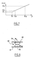
- the energy domain E between e 1 and e 2 may correspond to the energy recommended for performing vascular treatment and the energies greater than e 3 may correspond to the energies required for hair removal.
- the control device 30 can authorize the transmission a flash.
- the control device 30 prevents the emission of a flash.
- control device 30 can prevent the emission of a flash as long as the pressure exerted P is less than value p 3 .
- the control device 30 can also be configured, if necessary, to adjust the energy E of the flash light according to the pressure P exerted at moment when the firing is triggered, by calculating according to the pressure P the energy E the most appropriate correspondent, for example by respecting a predetermined law which is for example a straight line as illustrated.
- the application pressure of the exit window on the skin by the treatment device 10 allows to bring the operator to have to exercise on the the patient's skin, enough pressure to expel the hemoglobin from the treated area during hair removal and, in the case of vascular treatment, to prevent the operator to exert excessive pressure which would result in the hemoglobin of the area to be treated and thus reduce the effectiveness of the flash.
- the processing device 10 advantageously comprises a detector 80, shown schematically in Figure 8, fixed on an inner wall 81 of the generator 11 and sensitive to opening a hood 82 to access its circuits e.
- this detector 80 comprises on the one hand a fixed part 83 constituted for example by an ILS contact and on the other hand a magnet 84 fixed on the cover 82 so as to allow the fixed part 83 to detect the removal of the hood 82.
- the fixed part 83 is connected to the control device 30 and the latter is configured to memorize the opening of the hood 82 and to prevent, in the absence predetermined intervention carried out by an authorized person, the treatment to work again.
- the control device 30 can be configured to decrement a card to chip introduced in the reader 17, for example to reduce an account of units of credit stored in the chip.
- the generator 11 is then configured so that when the account no longer has credit units, the issuance of a flash is prevented.
- the processing device 10 can be used as follows.
- the operator introduces a smart card loaded in the reader 17 and programs using the keyboard 18 the nature of the desired treatment, for example a treatment delaying the regrowth of the hair, permanent hair removal, anti-wrinkle or vascular treatment .
- the operator can enter the desired energy density value directly, but the control device 30 may be configured to control the electronic switches 22 so as to stop the discharge of the capacitors 21 when the energy delivered by the lamp 60 reaches a predetermined value, which can be set for example at 20 J / cm 2 for safety.
- the handpiece 12 includes a trigger (not shown) which allows the operator to trigger the emission of at least one flash of light.
- the generator 11 prevents the transmission of a flash even when the trigger is actuated, in the absence of sufficient pressure exerted by the handpiece 12 on the skin or when the pressure exerted does not correspond not at the required pressure, given the nature of the treatment.
- the pressure sensor can be deleted or replaced by any other type of sensor, such as a contact or distance sensor, which can reduce the risk of a lightning strike in a direction other than the area to be treated.
Landscapes
- Physics & Mathematics (AREA)
- Health & Medical Sciences (AREA)
- Surgery (AREA)
- Optics & Photonics (AREA)
- Life Sciences & Earth Sciences (AREA)
- Molecular Biology (AREA)
- General Health & Medical Sciences (AREA)
- Nuclear Medicine, Radiotherapy & Molecular Imaging (AREA)
- Engineering & Computer Science (AREA)
- Biomedical Technology (AREA)
- Heart & Thoracic Surgery (AREA)
- Medical Informatics (AREA)
- Electromagnetism (AREA)
- Animal Behavior & Ethology (AREA)
- Otolaryngology (AREA)
- Public Health (AREA)
- Veterinary Medicine (AREA)
- Radiation-Therapy Devices (AREA)
- Finger-Pressure Massage (AREA)
- Stroboscope Apparatuses (AREA)
- Cleaning In General (AREA)
- Polarising Elements (AREA)
- Treatments Of Macromolecular Shaped Articles (AREA)
- Heating, Cooling, Or Curing Plastics Or The Like In General (AREA)
- Physical Or Chemical Processes And Apparatus (AREA)
Abstract
Description
- la figure 1 représente de manière schématique, en perspective, un dispositif de traitement,
- la figure 2 représente de manière schématique et simplifiée un étage de sortie pouvant être utilisé,
- la figure 3 illustre l'utilisation d'un disjoncteur différentiel,
- la figure 4 illustre l'utilisation d'une bobine saturable, reliée électriquement en série avec la lampe flash,
- la figure 5 représente de manière schématique l'évolution du courant IL de la lampe et de la tension VG de l'étage de sortie en fonction du temps,
- la figure 6 représente isolément et schématiquement un capteur de pression,
- la figure 7 illustre la possibilité de conditionner l'émission d'un flash lumineux à des conditions de pression particulières de la pièce à main sur la zone traitée, et
- la figure 8 représente un exemple de détecteur d'ouverture.
Claims (17)
- Dispositif de traitement par émission de flashs lumineux, comportant un lecteur (17) d'un support d'unités de crédit, le dispositif étant configuré pour décrémenter un compte d'utilisateur à chaque utilisation, notamment à chaque émission de flashs lumineux.
- Dispositif selon la revendication précédente, dans lequel le support d'unités de crédit est une carte à puce.
- Dispositif selon l'une des deux revendications précédentes, comportant une lampe flash (60) et un générateur (11) auquel est reliée la lampe flash, le générateur électrique (11) comportant plusieurs interrupteurs électroniques (22) associés chacun à un condensateur (21) respectif, chaque interrupteur électronique (22) pouvant être commandé d'un état non passant à un état passant permettant à de l'énergie électrique accumulée dans le condensateur associé d'être déchargée dans la lampe, caractérisé par le fait que la capacité de chaque condensateur (21) est suffisamment faible pour qu'en cas de défaillance de l'interrupteur électronique correspondant et la décharge dans la lampe (60) de la totalité de l'énergie électrique accumulée dans le condensateur (21), le flash lumineux ainsi généré ait une densité d'énergie suffisamment faible pour ne pas occasionner de risque de lésion indésirable de la zone traitée.
- Dispositif de traitement selon l'une quelconque des revendications précédentes, caractérisé par le fait qu'il comporte un dispositif de contrôle (30) pour commander les interrupteurs électroniques (22).
- Dispositif de traitement selon la revendication 4, caractérisé par le fait que les interrupteurs électroniques (22) sont commandés simultanément en commutation de l'état non passant à l'état passant.
- Dispositif de traitement selon l'une des revendications 4 et 5, caractérisé par le fait que le dispositif de contrôle (30) est configuré pour commuter de l'état passant à l'état non passant les interrupteurs électroniques lorsqu'une énergie prédéterminée a été déchargée dans la lampe.
- Dispositif de traitement selon l'une quelconque des revendications 4 à 7, caractérisé par le fait que le dispositif de contrôle est programmable de manière à permettre à un utilisateur de programmer l'énergie du flash lumineux, cette programmation pouvant s'effectuer en appuyant sur des touches (18) correspondant chacune à une nature de traitement.
- Dispositif de traitement selon l'une quelconque des revendications précédentes, caractérisé par le fait qu'il comporte un dispositif de détection de défaut d'isolation (31).
- Dispositif de traitement selon la revendication précédente, caractérisé par le fait que le dispositif de détection de défaut d'isolation (31) est configuré pour détecter une variation de potentiel aux bornes de deux résistances (25, 26) reliées en série, ayant un point milieu relié à la terre et des bornes reliées aux deux polarités d'une alimentation (20) des condensateurs.
- Dispositif de traitement selon l'une des revendications 8 et 9, caractérisé par le fait que le dispositif de détection de défaut d'isolation (31) est configuré pour détecter un courant de fuite inférieur à 100 µA, de préférence inférieur à 50 µA.
- Dispositif de traitement selon l'une quelconque des revendications précédentes, caractérisé par le fait qu'un liquide de refroidissement isolant électrique, notamment de l'eau déminéralisée, est utilisé pour refroidir la lampe, ce liquide venant en contact électrique entre la terre et l'une des deux polarités des condensateurs.
- Dispositif de traitement selon l'une quelconque des revendications précédentes, caractérisé par le fait qu'il est dépourvu d'alimentation électrique en mode simmer de la lampe flash (60).
- Dispositif de traitement selon l'une quelconque des revendications précédentes, caractérisé par le fait qu'au moins une bobine saturable (50) est reliée électriquement en série avec la lampe (60).
- Dispositif de traitement selon l'une quelconque des revendications précédentes, caractérisé par le fait que le dispositif de contrôle est configuré pour recevoir une information d'au moins un capteur (70) apte à délivrer une information représentative d'un contact ou d'une proximité de la pièce à main avec la zone à traiter et de préférence représentative également de la pression avec laquelle une pièce à main (12) contenant la lampe est appliquée sur la zone à traiter.
- Dispositif de traitement selon l'une quelconque des revendications précédentes, caractérisé par le fait qu'il est configuré pour ne pas permettre l'émission d'un flash tant que la pression exercée par la pièce à main (12) sur la zone à traiter est inférieure ou égale à une limite prédéterminée.
- Dispositif de traitement selon l'une quelconque des revendications précédentes, caractérisé par le fait qu'il est configuré pour ne pas permettre l'émission d'un flash lumineux tant que la pression d'application de la pièce à main (12) sur la zone à traiter n'est pas comprise entre des limites inférieure et supérieure prédéterminées, pour une nature de traitement donnée.
- Dispositif de traitement selon l'une quelconque des revendications précédentes, caractérisé par le fait qu'il comporte au moins un détecteur apte à détecter une ouverture d'un capot amovible (82) du générateur (11) et par le fait que le dispositif de traitement est configuré pour mémoriser l'ouverture du capot et empêcher qu'en l'absence d'une intervention prédéterminée, effectuée par une personne autorisée, le dispositif de traitement puisse fonctionner à nouveau.
Applications Claiming Priority (3)
| Application Number | Priority Date | Filing Date | Title |
|---|---|---|---|
| FR0204313 | 2002-04-08 | ||
| FR0204313A FR2838042B1 (fr) | 2002-04-08 | 2002-04-08 | Dispositif de traitement par emission de flashs lumineux |
| EP03290870A EP1352615B1 (fr) | 2002-04-08 | 2003-04-08 | Dispositif de traitement par émission de flashs lumineux |
Related Parent Applications (2)
| Application Number | Title | Priority Date | Filing Date |
|---|---|---|---|
| EP03290870.9 Division | 2003-04-08 | ||
| EP03290870A Division EP1352615B1 (fr) | 2002-04-08 | 2003-04-08 | Dispositif de traitement par émission de flashs lumineux |
Publications (3)
| Publication Number | Publication Date |
|---|---|
| EP1602340A2 true EP1602340A2 (fr) | 2005-12-07 |
| EP1602340A3 EP1602340A3 (fr) | 2006-01-11 |
| EP1602340B1 EP1602340B1 (fr) | 2011-06-15 |
Family
ID=28052172
Family Applications (2)
| Application Number | Title | Priority Date | Filing Date |
|---|---|---|---|
| EP05019414A Expired - Lifetime EP1602340B1 (fr) | 2002-04-08 | 2003-04-08 | Dispositif de traitement par émission de flashs lumineux |
| EP03290870A Expired - Lifetime EP1352615B1 (fr) | 2002-04-08 | 2003-04-08 | Dispositif de traitement par émission de flashs lumineux |
Family Applications After (1)
| Application Number | Title | Priority Date | Filing Date |
|---|---|---|---|
| EP03290870A Expired - Lifetime EP1352615B1 (fr) | 2002-04-08 | 2003-04-08 | Dispositif de traitement par émission de flashs lumineux |
Country Status (5)
| Country | Link |
|---|---|
| EP (2) | EP1602340B1 (fr) |
| AT (2) | ATE308281T1 (fr) |
| DE (1) | DE60302096T2 (fr) |
| ES (2) | ES2367899T3 (fr) |
| FR (1) | FR2838042B1 (fr) |
Families Citing this family (6)
| Publication number | Priority date | Publication date | Assignee | Title |
|---|---|---|---|---|
| FR2862204B1 (fr) * | 2003-11-13 | 2006-02-10 | Yves Vincent Brottier | Appareil d'epilation par decharges electriques dans une lampe flash regulee en courant |
| FR2864440B1 (fr) | 2003-12-26 | 2006-03-17 | Eurofeedback Sa | Piece a main comportant au moins un tube flash |
| FR2860704B1 (fr) * | 2004-12-15 | 2009-02-13 | Eurofeedback Sa | Dispositif de traitement par emission de flashs lumineux. |
| FR2889440A1 (fr) | 2005-08-05 | 2007-02-09 | Eurofeedback Sa | Appareil de traitement par emission de flashs lumineux, notamment d'epilation |
| FR2892012B1 (fr) | 2005-10-17 | 2008-07-18 | Eurofeedback Sa | Procede d'epilation |
| US20120195078A1 (en) * | 2011-02-01 | 2012-08-02 | Michael Levin | Prevention of safety hazards due to leakage current |
Family Cites Families (11)
| Publication number | Priority date | Publication date | Assignee | Title |
|---|---|---|---|---|
| DE875679C (de) * | 1942-11-21 | 1953-05-04 | Siemens Ag | Beruehrungsschutzschaltung fuer elektrische Geraete |
| US4745613A (en) * | 1987-01-09 | 1988-05-17 | General Electric Co. | Laser flash lamp triggering circuit |
| DE3800291A1 (de) * | 1988-01-08 | 1989-07-20 | Lauerer Friedrich | Elektrische sicherheitsschaltung |
| US5720772A (en) | 1992-10-20 | 1998-02-24 | Esc Medical Systems Ltd. | Method and apparatus for therapeutic electromagnetic treatment |
| US5287380A (en) * | 1993-02-19 | 1994-02-15 | Candela Laser Corporation | Method and apparatus for generating long output pulses from flashlamp-excited lasers |
| US5735844A (en) * | 1995-02-01 | 1998-04-07 | The General Hospital Corporation | Hair removal using optical pulses |
| EP0901349A2 (fr) * | 1996-04-09 | 1999-03-17 | Cynosure, Inc. | Systeme de laser a l'alexandrite, destine au traitement d'echantillons dermatologiques |
| US6251113B1 (en) * | 1996-08-29 | 2001-06-26 | Bausch & Lomb Surgical, Inc. | Ophthalmic microsurgical system employing surgical module employing flash EEPROM and reprogrammable modules |
| EP0885629A3 (fr) | 1997-06-16 | 1999-07-21 | Danish Dermatologic Development A/S | Dispositif de génération d'impulsions lumineuses et de phototraitement cosmétique et thérapeutique |
| US6214035B1 (en) * | 1999-03-23 | 2001-04-10 | Jackson Streeter | Method for improving cardiac microcirculation |
| AU2001256642A1 (en) * | 2000-05-19 | 2001-11-26 | Ib Soft Ltd. | Method and apparatus for applying electromagnetic radiation into human tissues for producing a therapeutic effect |
-
2002
- 2002-04-08 FR FR0204313A patent/FR2838042B1/fr not_active Expired - Lifetime
-
2003
- 2003-04-08 EP EP05019414A patent/EP1602340B1/fr not_active Expired - Lifetime
- 2003-04-08 ES ES05019414T patent/ES2367899T3/es not_active Expired - Lifetime
- 2003-04-08 AT AT03290870T patent/ATE308281T1/de not_active IP Right Cessation
- 2003-04-08 AT AT05019414T patent/ATE512635T1/de not_active IP Right Cessation
- 2003-04-08 EP EP03290870A patent/EP1352615B1/fr not_active Expired - Lifetime
- 2003-04-08 DE DE60302096T patent/DE60302096T2/de not_active Expired - Lifetime
- 2003-04-08 ES ES03290870T patent/ES2252628T3/es not_active Expired - Lifetime
Also Published As
| Publication number | Publication date |
|---|---|
| EP1352615B1 (fr) | 2005-11-02 |
| EP1602340B1 (fr) | 2011-06-15 |
| FR2838042A1 (fr) | 2003-10-10 |
| ES2367899T3 (es) | 2011-11-10 |
| DE60302096D1 (de) | 2005-12-08 |
| DE60302096T2 (de) | 2006-07-20 |
| ATE308281T1 (de) | 2005-11-15 |
| FR2838042B1 (fr) | 2005-03-11 |
| ATE512635T1 (de) | 2011-07-15 |
| EP1602340A3 (fr) | 2006-01-11 |
| EP1352615A1 (fr) | 2003-10-15 |
| ES2252628T3 (es) | 2006-05-16 |
Similar Documents
| Publication | Publication Date | Title |
|---|---|---|
| EP0314222B1 (fr) | Dispositif pour le transfert d'énergie électrique | |
| EP1352615B1 (fr) | Dispositif de traitement par émission de flashs lumineux | |
| US9970971B2 (en) | Flashlamp degradation monitoring system and method | |
| FR2509926A1 (fr) | Circuit d'onduleur a commutation rapide | |
| EP1632266A1 (fr) | Instrument de beauté | |
| FR2921249A1 (fr) | Dispositif de traitement par emission de flashs lumineux | |
| EP0705447B1 (fr) | Procede et dispositif pour detecter et identifier des cables electriques | |
| FR2558304A1 (fr) | Lampe a incandescence a circuit de ballast ameliore | |
| FR2911469A1 (fr) | Alimentation electrique d'un tube a rayons x et son procede de mise en oeuvre | |
| FR2860704A1 (fr) | Dispositif de traitement par emission de flashs lumineux. | |
| FR2709225A1 (fr) | Appareil pour clôture électrique. | |
| EP0320358A1 (fr) | Perfectionnements aux dispositifs de protection contre la foudre | |
| FR2749515A1 (fr) | Caisson d'isolation a emissions ou methodes de relaxation personnalisees | |
| FR2485164A1 (fr) | Controleur de flammes a securite intrinseque | |
| EP0374055B1 (fr) | Clôture électrique à contrôleur incorporé | |
| FR2536540A1 (fr) | Dispositif de detection de la presence de tension sur les installations electriques | |
| EP1230947A1 (fr) | Dispositif médical implantable actif, notamment stimulateur cardiaque, défibrillateur et/ou cardioverteur ou dispositif multisite, avec test de capture cycle à cycle | |
| EP0035447B1 (fr) | Procédé et dispositif de traitement de fils ou de fibres textiles | |
| FR2633837A1 (fr) | Circuit de charge-decharge pour le condensateur d'un defibrillateur cardiaque | |
| CA2248943A1 (fr) | Appareil destructeur d'elements metalliques tels que des aiguilles | |
| FR2497052A1 (fr) | Dispositif d'eclairage fluorescent a double niveau d'eclairage | |
| WO2022188989A1 (fr) | Dispositif de gant de dissuasion et d'application d'impulsion électrique | |
| EP0179680B1 (fr) | Circuit d'alimentation pour émetteur de rayons x, utilisable en radiologie | |
| EP0785703B1 (fr) | Dispositif de commande pour lampe fluorescente à basse pression | |
| EP0381585B1 (fr) | Système de contrôle pour clôtures électriques |
Legal Events
| Date | Code | Title | Description |
|---|---|---|---|
| PUAI | Public reference made under article 153(3) epc to a published international application that has entered the european phase |
Free format text: ORIGINAL CODE: 0009012 |
|
| PUAL | Search report despatched |
Free format text: ORIGINAL CODE: 0009013 |
|
| 17P | Request for examination filed |
Effective date: 20050907 |
|
| AC | Divisional application: reference to earlier application |
Ref document number: 1352615 Country of ref document: EP Kind code of ref document: P |
|
| AK | Designated contracting states |
Kind code of ref document: A2 Designated state(s): AT BE BG CH CY CZ DE DK EE ES FI FR GB GR HU IE IT LI LU MC NL PT RO SE SI SK TR |
|
| AK | Designated contracting states |
Kind code of ref document: A3 Designated state(s): AT BE BG CH CY CZ DE DK EE ES FI FR GB GR HU IE IT LI LU MC NL PT RO SE SI SK TR |
|
| AKX | Designation fees paid |
Designated state(s): AT BE BG CH CY CZ DE DK EE ES FI FR GB GR HU IE IT LI LU MC NL PT RO SE SI SK TR |
|
| GRAP | Despatch of communication of intention to grant a patent |
Free format text: ORIGINAL CODE: EPIDOSNIGR1 |
|
| GRAS | Grant fee paid |
Free format text: ORIGINAL CODE: EPIDOSNIGR3 |
|
| GRAA | (expected) grant |
Free format text: ORIGINAL CODE: 0009210 |
|
| AC | Divisional application: reference to earlier application |
Ref document number: 1352615 Country of ref document: EP Kind code of ref document: P |
|
| AK | Designated contracting states |
Kind code of ref document: B1 Designated state(s): AT BE BG CH CY CZ DE DK EE ES FI FR GB GR HU IE IT LI LU MC NL PT RO SE SI SK TR |
|
| REG | Reference to a national code |
Ref country code: GB Ref legal event code: FG4D Free format text: NOT ENGLISH Ref country code: CH Ref legal event code: EP |
|
| REG | Reference to a national code |
Ref country code: IE Ref legal event code: FG4D Free format text: LANGUAGE OF EP DOCUMENT: FRENCH |
|
| REG | Reference to a national code |
Ref country code: DE Ref legal event code: R096 Ref document number: 60337447 Country of ref document: DE Effective date: 20110721 |
|
| REG | Reference to a national code |
Ref country code: NL Ref legal event code: VDEP Effective date: 20110615 |
|
| PG25 | Lapsed in a contracting state [announced via postgrant information from national office to epo] |
Ref country code: SE Free format text: LAPSE BECAUSE OF FAILURE TO SUBMIT A TRANSLATION OF THE DESCRIPTION OR TO PAY THE FEE WITHIN THE PRESCRIBED TIME-LIMIT Effective date: 20110615 |
|
| REG | Reference to a national code |
Ref country code: ES Ref legal event code: FG2A Ref document number: 2367899 Country of ref document: ES Kind code of ref document: T3 Effective date: 20111110 |
|
| PG25 | Lapsed in a contracting state [announced via postgrant information from national office to epo] |
Ref country code: GR Free format text: LAPSE BECAUSE OF FAILURE TO SUBMIT A TRANSLATION OF THE DESCRIPTION OR TO PAY THE FEE WITHIN THE PRESCRIBED TIME-LIMIT Effective date: 20110916 Ref country code: CY Free format text: LAPSE BECAUSE OF FAILURE TO SUBMIT A TRANSLATION OF THE DESCRIPTION OR TO PAY THE FEE WITHIN THE PRESCRIBED TIME-LIMIT Effective date: 20110615 Ref country code: AT Free format text: LAPSE BECAUSE OF FAILURE TO SUBMIT A TRANSLATION OF THE DESCRIPTION OR TO PAY THE FEE WITHIN THE PRESCRIBED TIME-LIMIT Effective date: 20110615 Ref country code: SI Free format text: LAPSE BECAUSE OF FAILURE TO SUBMIT A TRANSLATION OF THE DESCRIPTION OR TO PAY THE FEE WITHIN THE PRESCRIBED TIME-LIMIT Effective date: 20110615 Ref country code: FI Free format text: LAPSE BECAUSE OF FAILURE TO SUBMIT A TRANSLATION OF THE DESCRIPTION OR TO PAY THE FEE WITHIN THE PRESCRIBED TIME-LIMIT Effective date: 20110615 |
|
| PG25 | Lapsed in a contracting state [announced via postgrant information from national office to epo] |
Ref country code: NL Free format text: LAPSE BECAUSE OF FAILURE TO SUBMIT A TRANSLATION OF THE DESCRIPTION OR TO PAY THE FEE WITHIN THE PRESCRIBED TIME-LIMIT Effective date: 20110615 |
|
| REG | Reference to a national code |
Ref country code: IE Ref legal event code: FD4D |
|
| PG25 | Lapsed in a contracting state [announced via postgrant information from national office to epo] |
Ref country code: CZ Free format text: LAPSE BECAUSE OF FAILURE TO SUBMIT A TRANSLATION OF THE DESCRIPTION OR TO PAY THE FEE WITHIN THE PRESCRIBED TIME-LIMIT Effective date: 20110615 Ref country code: EE Free format text: LAPSE BECAUSE OF FAILURE TO SUBMIT A TRANSLATION OF THE DESCRIPTION OR TO PAY THE FEE WITHIN THE PRESCRIBED TIME-LIMIT Effective date: 20110615 Ref country code: PT Free format text: LAPSE BECAUSE OF FAILURE TO SUBMIT A TRANSLATION OF THE DESCRIPTION OR TO PAY THE FEE WITHIN THE PRESCRIBED TIME-LIMIT Effective date: 20111017 Ref country code: IE Free format text: LAPSE BECAUSE OF FAILURE TO SUBMIT A TRANSLATION OF THE DESCRIPTION OR TO PAY THE FEE WITHIN THE PRESCRIBED TIME-LIMIT Effective date: 20110615 |
|
| PG25 | Lapsed in a contracting state [announced via postgrant information from national office to epo] |
Ref country code: RO Free format text: LAPSE BECAUSE OF FAILURE TO SUBMIT A TRANSLATION OF THE DESCRIPTION OR TO PAY THE FEE WITHIN THE PRESCRIBED TIME-LIMIT Effective date: 20110615 Ref country code: SK Free format text: LAPSE BECAUSE OF FAILURE TO SUBMIT A TRANSLATION OF THE DESCRIPTION OR TO PAY THE FEE WITHIN THE PRESCRIBED TIME-LIMIT Effective date: 20110615 |
|
| PLBE | No opposition filed within time limit |
Free format text: ORIGINAL CODE: 0009261 |
|
| STAA | Information on the status of an ep patent application or granted ep patent |
Free format text: STATUS: NO OPPOSITION FILED WITHIN TIME LIMIT |
|
| 26N | No opposition filed |
Effective date: 20120316 |
|
| PG25 | Lapsed in a contracting state [announced via postgrant information from national office to epo] |
Ref country code: DK Free format text: LAPSE BECAUSE OF FAILURE TO SUBMIT A TRANSLATION OF THE DESCRIPTION OR TO PAY THE FEE WITHIN THE PRESCRIBED TIME-LIMIT Effective date: 20110615 |
|
| REG | Reference to a national code |
Ref country code: DE Ref legal event code: R097 Ref document number: 60337447 Country of ref document: DE Effective date: 20120316 |
|
| BERE | Be: lapsed |
Owner name: EUROFEEDBACK Effective date: 20120430 |
|
| PG25 | Lapsed in a contracting state [announced via postgrant information from national office to epo] |
Ref country code: MC Free format text: LAPSE BECAUSE OF NON-PAYMENT OF DUE FEES Effective date: 20120430 |
|
| REG | Reference to a national code |
Ref country code: CH Ref legal event code: PL |
|
| PG25 | Lapsed in a contracting state [announced via postgrant information from national office to epo] |
Ref country code: BE Free format text: LAPSE BECAUSE OF NON-PAYMENT OF DUE FEES Effective date: 20120430 Ref country code: CH Free format text: LAPSE BECAUSE OF NON-PAYMENT OF DUE FEES Effective date: 20120430 Ref country code: LI Free format text: LAPSE BECAUSE OF NON-PAYMENT OF DUE FEES Effective date: 20120430 |
|
| PGFP | Annual fee paid to national office [announced via postgrant information from national office to epo] |
Ref country code: ES Payment date: 20130320 Year of fee payment: 11 |
|
| PG25 | Lapsed in a contracting state [announced via postgrant information from national office to epo] |
Ref country code: BG Free format text: LAPSE BECAUSE OF FAILURE TO SUBMIT A TRANSLATION OF THE DESCRIPTION OR TO PAY THE FEE WITHIN THE PRESCRIBED TIME-LIMIT Effective date: 20110915 |
|
| PGFP | Annual fee paid to national office [announced via postgrant information from national office to epo] |
Ref country code: DE Payment date: 20130430 Year of fee payment: 11 Ref country code: GB Payment date: 20130422 Year of fee payment: 11 |
|
| PGFP | Annual fee paid to national office [announced via postgrant information from national office to epo] |
Ref country code: IT Payment date: 20130424 Year of fee payment: 11 |
|
| PG25 | Lapsed in a contracting state [announced via postgrant information from national office to epo] |
Ref country code: TR Free format text: LAPSE BECAUSE OF FAILURE TO SUBMIT A TRANSLATION OF THE DESCRIPTION OR TO PAY THE FEE WITHIN THE PRESCRIBED TIME-LIMIT Effective date: 20110615 |
|
| PG25 | Lapsed in a contracting state [announced via postgrant information from national office to epo] |
Ref country code: LU Free format text: LAPSE BECAUSE OF NON-PAYMENT OF DUE FEES Effective date: 20120408 |
|
| PG25 | Lapsed in a contracting state [announced via postgrant information from national office to epo] |
Ref country code: HU Free format text: LAPSE BECAUSE OF FAILURE TO SUBMIT A TRANSLATION OF THE DESCRIPTION OR TO PAY THE FEE WITHIN THE PRESCRIBED TIME-LIMIT Effective date: 20030408 |
|
| REG | Reference to a national code |
Ref country code: DE Ref legal event code: R119 Ref document number: 60337447 Country of ref document: DE |
|
| GBPC | Gb: european patent ceased through non-payment of renewal fee |
Effective date: 20140408 |
|
| PG25 | Lapsed in a contracting state [announced via postgrant information from national office to epo] |
Ref country code: DE Free format text: LAPSE BECAUSE OF NON-PAYMENT OF DUE FEES Effective date: 20141101 Ref country code: GB Free format text: LAPSE BECAUSE OF NON-PAYMENT OF DUE FEES Effective date: 20140408 |
|
| REG | Reference to a national code |
Ref country code: DE Ref legal event code: R119 Ref document number: 60337447 Country of ref document: DE Effective date: 20141101 |
|
| PG25 | Lapsed in a contracting state [announced via postgrant information from national office to epo] |
Ref country code: IT Free format text: LAPSE BECAUSE OF NON-PAYMENT OF DUE FEES Effective date: 20140408 |
|
| REG | Reference to a national code |
Ref country code: ES Ref legal event code: FD2A Effective date: 20150526 |
|
| PG25 | Lapsed in a contracting state [announced via postgrant information from national office to epo] |
Ref country code: ES Free format text: LAPSE BECAUSE OF NON-PAYMENT OF DUE FEES Effective date: 20140409 |
|
| REG | Reference to a national code |
Ref country code: FR Ref legal event code: PLFP Year of fee payment: 14 |
|
| REG | Reference to a national code |
Ref country code: FR Ref legal event code: PLFP Year of fee payment: 15 |
|
| REG | Reference to a national code |
Ref country code: FR Ref legal event code: PLFP Year of fee payment: 16 |
|
| PGFP | Annual fee paid to national office [announced via postgrant information from national office to epo] |
Ref country code: FR Payment date: 20220228 Year of fee payment: 20 |