EP1602609A2 - Dispositifs pour le traitement et l'entraínement d'un matériau en bande - Google Patents
Dispositifs pour le traitement et l'entraínement d'un matériau en bande Download PDFInfo
- Publication number
- EP1602609A2 EP1602609A2 EP05104189A EP05104189A EP1602609A2 EP 1602609 A2 EP1602609 A2 EP 1602609A2 EP 05104189 A EP05104189 A EP 05104189A EP 05104189 A EP05104189 A EP 05104189A EP 1602609 A2 EP1602609 A2 EP 1602609A2
- Authority
- EP
- European Patent Office
- Prior art keywords
- web
- drive
- movable
- former
- threaded spindle
- Prior art date
- Legal status (The legal status is an assumption and is not a legal conclusion. Google has not performed a legal analysis and makes no representation as to the accuracy of the status listed.)
- Granted
Links
Images




Classifications
-
- B—PERFORMING OPERATIONS; TRANSPORTING
- B65—CONVEYING; PACKING; STORING; HANDLING THIN OR FILAMENTARY MATERIAL
- B65H—HANDLING THIN OR FILAMENTARY MATERIAL, e.g. SHEETS, WEBS, CABLES
- B65H35/00—Delivering articles from cutting or line-perforating machines; Article or web delivery apparatus incorporating cutting or line-perforating devices, e.g. adhesive tape dispensers
- B65H35/02—Delivering articles from cutting or line-perforating machines; Article or web delivery apparatus incorporating cutting or line-perforating devices, e.g. adhesive tape dispensers from or with longitudinal slitters or perforators
-
- B—PERFORMING OPERATIONS; TRANSPORTING
- B65—CONVEYING; PACKING; STORING; HANDLING THIN OR FILAMENTARY MATERIAL
- B65H—HANDLING THIN OR FILAMENTARY MATERIAL, e.g. SHEETS, WEBS, CABLES
- B65H23/00—Registering, tensioning, smoothing or guiding webs
- B65H23/04—Registering, tensioning, smoothing or guiding webs longitudinally
- B65H23/26—Registering, tensioning, smoothing or guiding webs longitudinally by transverse stationary or adjustable bars or rollers
-
- B—PERFORMING OPERATIONS; TRANSPORTING
- B65—CONVEYING; PACKING; STORING; HANDLING THIN OR FILAMENTARY MATERIAL
- B65H—HANDLING THIN OR FILAMENTARY MATERIAL, e.g. SHEETS, WEBS, CABLES
- B65H45/00—Folding thin material
- B65H45/12—Folding articles or webs with application of pressure to define or form crease lines
- B65H45/22—Longitudinal folders, i.e. for folding moving sheet material parallel to the direction of movement
- B65H45/221—Longitudinal folders, i.e. for folding moving sheet material parallel to the direction of movement incorporating folding triangles
-
- B—PERFORMING OPERATIONS; TRANSPORTING
- B65—CONVEYING; PACKING; STORING; HANDLING THIN OR FILAMENTARY MATERIAL
- B65H—HANDLING THIN OR FILAMENTARY MATERIAL, e.g. SHEETS, WEBS, CABLES
- B65H45/00—Folding thin material
- B65H45/12—Folding articles or webs with application of pressure to define or form crease lines
- B65H45/22—Longitudinal folders, i.e. for folding moving sheet material parallel to the direction of movement
- B65H45/221—Longitudinal folders, i.e. for folding moving sheet material parallel to the direction of movement incorporating folding triangles
- B65H45/226—Positional adjustment of folding triangles
-
- B—PERFORMING OPERATIONS; TRANSPORTING
- B65—CONVEYING; PACKING; STORING; HANDLING THIN OR FILAMENTARY MATERIAL
- B65H—HANDLING THIN OR FILAMENTARY MATERIAL, e.g. SHEETS, WEBS, CABLES
- B65H2301/00—Handling processes for sheets or webs
- B65H2301/40—Type of handling process
- B65H2301/41—Winding, unwinding
- B65H2301/414—Winding
- B65H2301/4148—Winding slitting
-
- B—PERFORMING OPERATIONS; TRANSPORTING
- B65—CONVEYING; PACKING; STORING; HANDLING THIN OR FILAMENTARY MATERIAL
- B65H—HANDLING THIN OR FILAMENTARY MATERIAL, e.g. SHEETS, WEBS, CABLES
- B65H2403/00—Power transmission; Driving means
- B65H2403/50—Driving mechanisms
- B65H2403/52—Translation screw-thread mechanisms
-
- B—PERFORMING OPERATIONS; TRANSPORTING
- B65—CONVEYING; PACKING; STORING; HANDLING THIN OR FILAMENTARY MATERIAL
- B65H—HANDLING THIN OR FILAMENTARY MATERIAL, e.g. SHEETS, WEBS, CABLES
- B65H2511/00—Dimensions; Position; Numbers; Identification; Occurrences
- B65H2511/10—Size; Dimensions
- B65H2511/12—Width
-
- B—PERFORMING OPERATIONS; TRANSPORTING
- B65—CONVEYING; PACKING; STORING; HANDLING THIN OR FILAMENTARY MATERIAL
- B65H—HANDLING THIN OR FILAMENTARY MATERIAL, e.g. SHEETS, WEBS, CABLES
- B65H2511/00—Dimensions; Position; Numbers; Identification; Occurrences
- B65H2511/20—Location in space
Definitions
- the invention relates to a device for processing and / or conveying a web according to the preamble of claim 1.
- EP 12 38 935 A2 is an apparatus for longitudinal cutting of films and Tapes known, with an upper blade for setting a cutting width across the Transport direction of the web is positionable.
- DE 196 02 248 A1 discloses a former, which for lateral correction of folded strand along an inlet gap of two subordinate rolls movable is.
- WO 01/70608 A1 is a positionable transversely to the direction of entry of the web Turning bar and a positionable along the inlet clearing of the web register roller known.
- the turning bar is pivotable in such a way that they depending on the position Turn the track to the right or left.
- DE 36 14 981 C2 discloses two web edge sensors, each having a drive have and be controlled by a common control device. something similar discloses DE 35 33 274 C3.
- each device an axial having movable feed device.
- a device with which it is possible, from a running paper web of maximum width to cut two partial webs or three partial webs of variable width and these To fold partial webs is known from DE 42 04 254 A1.
- the device shown there comprises three formers arranged in two planes, two in a first Level adjacent formers traversed transversely to the direction of the paper web are arranged to selectively for folding both partial webs of a two-part Paper web or for folding the two outer partial webs of a tripartite train to serve.
- An adaptation of other web-guiding facilities than the former to the respective web width is not provided.
- DE 100 03 025 C1 discloses a device for processing a web with at least one former and this upstream as a knife, wherein the Knife and the former through a common actuator transverse to the direction of the railway are movable.
- EP 0 457 304 A1 relates to a mechanism with two in opposite directions by a common drive movable processing elements of a device for folding of bags.
- the invention is based on the object, a device for processing and / or To promote a railway.
- a particular advantage of the invention is that it allows rapid adaptation to a Changing the web widths to be processed, as a user does not open each to be moved in adaptation to the web width Web editing tool must access individually.
- control unit itself is set up necessarily correlated positions of the different Automatic editing tools from a small number of input parameters calculate and adjust. In the simplest case, it is sufficient to calculate this Positions to specify only the width of a web to be processed; the Control unit can from this specification the required positions of all Determine editing tools in a simple way on condition that a Reference line of all webs to be processed, z. B. a right or left margin or preferably the center line, regardless of their width in the device the same Takes position.
- the device can be Simplify by using an actuator to move multiple Web processing tools is used simultaneously.
- Belongs to the web processing tools of the device according to the invention for example, at least one former.
- the reference line it can are sufficient if only one of two formers is displaceable; However, you choose what is preferred, the center line of the web to be processed as a reference line, so must at least both of two juxtaposed folders to be displaced.
- the device according to the invention expediently at least one Knife for longitudinal cutting of the original web in partial webs. If more than one such knife is present, at least one of them must be displaceable.
- the device may further comprise at least one interval cutting knife for page-wise Having slitting the web. If the material web is a printed paper web, in particular a newspaper, may be such Intermittent cutting knives are used to lift the web locally at the height of each second side to cut so z. B. a broadsheet signature with tabloid insert too to produce.
- the device has a longitudinal cutting device has at least one knife, which also transverse to the direction of the web is preset to set the cutting line for the partial webs to be produced.
- Turning bars can also be displaced by the control unit Processing tools are provided. As editing tools are here and in the following also Bruleit-, Bruantriebs- and / or web guide elements, such as z. As turner bars, pressure rollers and / or guide rollers understood.
- the actuators preferably in each case a threaded spindle, and the displaceable Machining tool each have a sliding block, with such a Threaded spindle is engaged.
- such a threaded spindle can have a plurality of sections which differ in sense of rotation and / or pitch, and the sliding blocks of several Machining tools of the same type are each in engagement with the various Sections of a same spindle coupled to the editing tools, but if necessary to move in different directions and / or speeds.
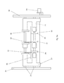
- Fig. 1a shows a former arrangement, in the two paper webs 01, 02 next to each other via a roller 03 and then in two formers 06, 07 are performed.
- the formers 06, 07 are in a frame 04 parallel to the axis of the roller 03rd slidably mounted.
- An actuator for moving the former 06, 07 is formed by a parallel to the axis of the roller 03 threaded spindle 08, the two sections with having opposite slope, and a drive 11, z. B. electric motor 11, for rotational driving the threaded spindle 08.
- the drive 11 and the former 06; 07 moving gear can also be carried out in other ways.
- the formers 06, 07 are each provided with a sliding block 09, wherein the two sliding blocks 09 with different sections of the threaded spindle 08 are engaged, so that a rotation the threaded spindle 08, the former 06, 07 drives to opposite movements.
- An electronic control unit 10 or a system S mentioned below Presetting controls the electric motor 11 based on a user at the Control unit 10 entered (or the system S present) width of the Paper webs 01, 02.
- the information about the width of the control device 10 in other ways, for. B. by reading a common value or one in a product planning system, a machine control, a Imposition scheme and / or a control station (denoted by P in FIG. 9) stored value.
- a connected to the left former 06 frame 15 or frame 15 is used at the same time as a support for a bearing of the roller 03, so that the roller 03 every movement the Former 06 follows.
- the right side of the roller 03 is on a frame 04 fixed pin telescopic, z. B. via an axially displaceable bearing 25 (Fig. 1 b), displaceable.
- Fig. 1 b axially displaceable bearing 25
- displaceable With the folding hopper 06, thus displacing the roller 03 and z. B. one on the roller 03 circumferential groove 20 (dashed line in Figure 1 b), which with a Knife for continuous or discontinuous longitudinal cutting as a cutting groove works together.
- Intervallschneidmesser 05 Also rigid with the former 06, z. B. on the frame 15, is connected Intervallschneidmesser 05 or Skip Slitter 05, which is mounted above the roller 03.
- the Intervallschneidmesser 05 has a rotating interrupted blade, with the Folding line of the former 06 aligned and alternately on the paper web 01 printed pairs of printed pages each alternately intersects a pair and that others left uncut.
- the uncut side pairs are around Broadsheet pages with transverse to the conveying direction lines and the sliced around tabloid sides whose rows are oriented in the conveying direction, so can be from the paper web 01 in a connected, not shown Folder in a simple way a signature with a deposit in half the page size produce.
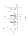
- Fig. 1 b is the setting of the former 06, 07 for the processing of two Paper webs 12, 13 shown opposite to the paper webs 01, 02 of FIG. 1 a are narrower by a value d.
- the center line M at which the tracks 12, 13 touch, has the same position with respect to the frame as the center line M between the Webs 01, 02 in Fig. 1a.
- the threaded spindle 08 rotated, so that the former 06, 07 each shifted by d / 2 to the center line M out become.
- the former 06; 07 in addition to or instead of the connection to the knife 05 - one of the funnel tip downstream driven roller 30 together or simultaneously with the Forming hopper 06; 07 laterally movable.
- the former 06; 07 preferably over a common frame 15 connected to a bearing of the roller 30. at Moving the former 6, 07, the roller 30 is moved simultaneously.
- the roller 30 is designed either as a driven transfer roller 30, via which a the former 06; 07 leaving strand is guided and undergoes a change in direction.
- the roller 30 as z. B. single motor driven tension roller 30 a Ceizenen be executed, against which a pressure roller 35 is adjustable. In In this case, the entire train group 30, 35 with the former 06; 07 connected.
- the controller 10 and the drive 11 for the described movement the former funnel 06; 07 is in signal communication with the system S.
- Production data eg the web or partial web width b; b '
- a predetermined or predefinable for this production situation compared and, if necessary, a corresponding movement via setting commands to the relevant Drive 11 causes.
- the Forming hopper 06; 07 is z. B.
- Preset values can be tabulated for the various productions, or it can be found in the System a calculation based on the by the web widths and the lateral offset resulting railways instead.
- Fig. 2a shows a catching roller arrangement as a further example of Web processing tools of a device according to the invention.
- These Fang roller assembly consists of a roller 14, which in operation of a catching, is wrapped in the figure, not shown paper web, a plurality of rollers 16, a plurality of sliding blocks 18, 19, 21, a guide rail 17, a threaded spindle 22nd and one of the already mentioned control unit 10 (or system S) controlled Electric motor 23.
- the roller 14 is rotatably mounted in the frame 04. Parallel to the roller 14 is the Guide rail 17 mounted in the frame 04. On the guide rail 17 are several Sliders 18, 19 arranged displaceably. A central to the roller 14 arranged Slider 21 is fixedly arranged on the guide rail 17.
- the sliding blocks 18, 19 and 21 each carry a rotatably mounted roller 16. The rollers 16 press against the Roller 14 and roll against this. Since the rollers 16 only rotate in one direction are designed to prevent them from running back around the roller 14 Paper web in case of a paper web break.
- the threaded spindle 22 pierces the frame 04 on one side and protrudes at this point out of frame 04 It is parallel to the roller 14 and the guide rail 17 aligned.
- the threaded spindle 22 has two different Thread sections with different directions of rotation, which by a threadless Section are separated. On this threadless section is the sliding block 21 arranged.
- the two threaded sections have slopes that run along one Longitudinal axis of the threaded spindle 22 proportional to the distance from the sliding block 21st increase.
- the sliding blocks 18, 19 are left with the seen from the sliding block 21 from or right threaded section not about an internal thread with several Windings engaged - such would be due to the variability of the slope stuck stay, but over a single narrow pin, which on a small Peripheral portion of the threaded spindle 22 engages in the thread on the off the frame 04 protruding end portion of the threaded spindle 22 engages the Electric motor 23 to the threaded spindle 22 at.
- the sliding blocks 18, 19 along the guide rail 17th shifted, as shown in Fig. 2b.
- the threaded spindle 22 via the drive 23rd turned. Due to the different sense of rotation of the two with the sliding blocks 18 and 19 engaged threaded portions move at a rotation of the Threaded spindle 22, the sliding blocks 18 from the left and the sliding blocks 19 from the right on the central sliding block 21 too.
- the movement of the sliding blocks 18, 19 takes place synchronously, however, as a result of changing along the longitudinal axis of the threaded spindle 22 Slopes of the threaded portions are the paths that the sliding blocks 18, 19 and thus the rollers they drive are 16, proportional to their distance from middle sliding block 21.
- the Sliders 18, 19 via a corresponding rotation of the threaded spindle 22 more or less close to the sliding block 21 steplessly move, and the Fangrolle so that set any paper web widths.
- the sliding blocks 18, 19 can before a Displacement can be arbitrarily placed on the spindle 22; the ratio of their distances remains with a shift.
- threaded spindles each with two sections of opposite be provided with the same pitch, the respective sliding blocks of each other with respect to the Bear center line M mirrored opposite roles.
- These threaded spindles are expediently identical to each other.
- the threaded spindles of a common electric motor via a gearbox with each adapted Gear ratio driven, or each threaded spindle has its own Electric motor provided by the control unit individually according to the required Shift is controlled.
- FIG. 3a shows a longitudinal cutting device 71 of a superstructure 67 (FIG. 9).
- the Longitudinal cutting device 71 is adapted to an incoming web in a plurality Partial webs, e.g. cut longitudinally two partial webs.
- a paper web 26 is passed between the two guide rails 24.
- Two carriages 27 are on the two guide rails 24 slidably held. They are mirror images of each other executed and mounted.
- Each carriage 27 carries a rotating knife 28 with vertical to the paper web 26 aligned cutting edge and one with the knife 28th cooperating counter-pressure roller 29 (counter knife).
- a parallel to the guide rails 24 threaded spindle 33 has two Thread sections with different directions of rotation and the same pitch, of which each engaged with one of the carriages 27.
- An end portion of the threaded spindle 33 protrudes from the frame 04 on one side.
- a drive 34, z. B. electric motor 34, for rotational driving of the threaded spindle 33 is provided.
- the single knife 28; 32 or counter knife can also be together by a different type of drive 34 or by individual drives per knife or knife pair be drivable.
- the threaded spindle 33rd rotated by the electric motor 34. Since the carriage 27 on different Threaded portions of the threaded spindle 33 with different rotation and the same Slope engaged, causes the rotation of the threaded spindle 33 that the Carriage 27 to each other equal distances to each other or to the central blade 32 to move. The rotation of the threaded spindle 33 is continued until the Distance between two knives 28, 32 one quarter of the width of the narrow paper web 36 corresponds.
- the operation of the motor 34 is controlled by the control unit 10 (or system S) ( Figure 1a). controlled or predetermined, the positions of the knife 28 based on a user widths set or automatically detected by sensors (not shown) cutting web or the partial webs resulting from the cutting.
- knife units may e.g. all individually driven and / or individually on / off.
- the axial positioning or at least presetting of the machine control is preferably automatically based on the intended for printing width of Track and the product-specific cut lines or from a control panel made manually. This is done, for example, before the production start of the system S (from the machine control or a corresponding software program) the current setting to the preset values required for the planned production checked and / or a default by acting on the drive 34 (or the Drives 34). Such default values can be tabulated for the be deposited in different productions, or it can be found in the system S one Calculation using the through the web widths and the to be obtained lateral offset instead.
- Fig. 4a is a turning table with two crossed turning bars 37, 38 as another Example of web processing tools shown to be present in the device can.
- Two pairs of guide rails 39, 41 as the front 41 and rear Guide rails 39, are held between plates of the frame 04. From Each pair of guide rails 39, 41 is only an upper guide rail in the figure too see as it covers the underlying to her underlying rail.
- a sliding block 42, 43 is provided, wherein the sliding block 42 on the visible upper guide rail 39 of the rear guide rail pair and the sliding block 43 on the visible upper guide rail 41 of the front Guide rail pair is slidably disposed.
- a deflection roller 47 rotatably arranged.
- a perpendicular to the guide rail pairs 39 and 41 incoming paper web 51st rotates the inclined turning bar 37 and thereby changes their direction of rotation by 90 °. she wraps around the guide roller 47 and runs from this back and over the oblique Asked, with the turning bar 37 crossed turning bar 38, which is their Changing direction again by 90 °, so that after leaving the turning table their original running direction has returned, but by exactly one paper web width is offset and turned.
- each spindle 48 engages a drive 49, e.g. an electric motor 49 on.
- the control unit 10 controls a opposite movement of the motors 49 and thus the turning bars 37, 38th Zum others, especially if more than two partial webs are to be processed, one same direction displacement of the turning bars 37, 38 may be required to ensure that the partial webs are not too close to the ends of the turning bars 37, 38 come.
- the control unit 10 controls the motors 49, respectively in the same direction.
- the reversing deck just described is shown in Fig. 5a after a conversion.
- the Turning bars 37 and 38 are parallel to each other in this embodiment Slide blocks 42, 43, 44, 46 on the guide rails of the pairs of guide rails 39 and 41 slidably arranged.
- a paper web 53 to be offset runs perpendicular to the guide rail pairs 39 and 41 in the turning corner, wraps successively the turning bar 37 and the Turning bar 38, and leaves the turning table laterally offset by a paper web width, without being turned.
- Fig. 6 shows an advantageous embodiment of the turning bar arrangement according to Fig. 4, wherein the arrangement, however, only one support 39; 41 for the two turning bars 37, 38.
- the sliding blocks 43; 46 slide on the same support 39; 41 and become driven by a common threaded spindle 48, which two opposing Has thread for each one of the sliding blocks.
- the spindle is driven by the motor 49 driven, wherein upon rotation of the threaded spindle, the sliding blocks 43; 46 move in opposite directions.
- Fig. 7 also shows an advantageous embodiment of the arrangement according to Fig. 5, wherein here as in Fig. 6, a common threaded spindle 48 with opposite threads for the Sliding blocks 43; 46 is provided.
- the sliding blocks 43; 46 are also running on the same Carrier 41.
- Driving the threaded spindle 48 through the common motor 49th causes an opposite movement of the two turning bars 37; 38 with her Sliding blocks 43; 46th
- a turning tool 72 of a printing machine has at least one turning table two mutually associated turning bars 37; 38, by means of which a partial web 51 until 54 can be brought to another flight and / or overthrown. It includes one Pair of turning bars 37; 38. In an advantageous embodiment, not shown here are two turning corners, i. two pairs of turning bars 37; 38 to the offset or to Falls of two partial webs 51 to 54 provided.
- the turning bars 37; 38 of a couple can be as shown either parallel to each other and 45 ° to the incoming Track can be arranged inclined (offset), or they are perpendicular to each other arranged and inclined at 45 ° or 135 ° to the incoming web (falls and possibly Offset).
- all turning bars 37; 38 in the level of each incoming web by 90 ° swivel or tilted executed.
- the carrier accounts for 39.
- the turning bars 37; 38 each an unillustrated means associated with which the current position of the turning bar 37; 38 - to the left or to Tilted to the right - recorded and sent to the machine control or the control console of the machine or the system S reports.
- These may be, for example, initiators, which mechanical (switch) or electromagnetic (induction, photocell) activated or be deactivated as soon as the turning bar 37; 38 in one of the intended locations located.
- the printer or a program can then check if the Turning bars 37; 38 in the position required for the planned production. It can be output by the system S an error signal when the position of the Turning bar 37; 38 to the intended production (or web run) does not match.
- Each turning bar 37; 38 is as shown above in a preferred embodiment in total arranged in a direction transverse to the incoming path movable in the superstructure 67.
- the turning bar 37; 38 adapted to a product or a web run or Web width can be positioned by means of the drive 49.
- the Drives 49 of the turning bars 37; 38 are in signal communication with the system S. Based on the production data (eg planned web guide, resulting theoretical cutting line, and / or web or partial web width), the current position of Turning bar 37; 38 with a predefined or predetermined for this production situation compared and, if necessary, a corresponding movement via setting commands to the relevant Drives 49 causes.
- Such default values can be tabulated for the be deposited in different productions, or it can be found in the system S one Calculation using the through the web widths and the to be obtained lateral offset instead.
- the pivotable turning bars 37; 38 associated with an unillustrated drive for panning, which, for example, like set forth for the drives 49, by the o. g. System S according to the planned Production and / or web guide is preset.
- a drive is advantageous For example, designed as a pressurizable cylinder, which on a Side with the frame and on the other with the turning bar 37; 38 outside of her Fulcrum attacks.
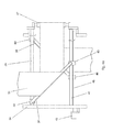
- Fig. 8 shows a schematic side view of the former as 06; 07 executed Web processing tool.
- the former 06; 07 is in an advantageous embodiment in a direction (at least one component) movable perpendicular to the Back fold of the former 06; 07 leaving strand and / or substantially parallel to a rotation axis of a cylinder (cross-cutting cylinder, Folding blade cylinder and / or jaw cylinder) of a downstream folder 68 (see Fig. 9).
- This allows the correct entry into the cylinders of the folder Adjust 68 for different web or strand widths and / or layers.
- an unillustrated drive for the described movement of the former 06; 07 in Signal connection with a controller 10 or advantageously with the system S is.
- Based the production data eg the rail or partial web width
- the production data is the current position of the Forming former 06; 07 with a predetermined or predefinable for this production situation compared and, if necessary, a corresponding movement via setting commands to the relevant Drive causes.
- a corresponding movement via setting commands to the relevant Drive causes.
- sectionbahn- or strand width of the former 06; 07 (or the funnel tip) to position accordingly.
- the former 06; 07 is z. B. Positioned such that the folded strand for each width in a suitable manner -.
- Preset values can be tabulated for the various productions, or it can be found in the System a calculation based on the by the web widths and the lateral offset resulting railways instead.
- the aforementioned web processing tools are single or multiple Part of a web-processing and / or processing machine, z. B. printing press (Fig. 9), in particular a web-fed rotary printing press for printing on or several tracks B.
- a web-fed rotary printing press for printing on or several tracks B.
- This has z. B. several units 61; 62; 63; 64; 65; 66; 67; 68; 69 for supply, for printing and for further processing.
- one Roll handling 61 becomes the web B to be covered, in particular paper web B, unwound before passing over a feeder 62 of one or more printing units 63 is supplied.
- Printing units 63 may include additional printing units Be provided 63, which then, for example, also alternately to one or several of the remaining printing units 63 can be used for the flying printing form change are.
- the printing units 63 can also be z.T. vertically above each other Bridge printing units 63 or as (nine- or ten-cylinder) satellite printing units be executed.
- a coating unit 64 may be provided in the web path.
- the web B passes through, for example, one Dryer 65 and is optionally cooled in a cooling unit 66 again, if the drying carried out in a thermal manner.
- a drying unit 66 at least one further, not shown in Fig. 9 conditioning device, such as. a coating device and / or a Wiederbefeuchtung be provided.
- the web B via a superstructure 67 a Folder 68 are supplied.
- the superstructure 67 has z. B. not in Fig. 1 illustrated silicone work, the longitudinal cutting device 71 and a at least one Reversing device having turning device 72 or Wendewerk 72 and a the or the formers 06; 07 having funnel unit 73.
- the said silicone work can also in front of the superstructure 67, e.g. be arranged in the region of the cooling unit 66.
- the Mathbaubau 67 can continue a not shown in Fig. 9 perforating, a gluing plant, have a numbering and / or a Pflugfalz. After passing through the superstructure 67 becomes the web B or partial webs B1; B2 guided in the folder 68.
- the printing press additionally has a separate one Sheeter 69, e.g. a so-called. Plano boom 69, on, in which an example not guided by the folding apparatus 68 web B cut in size sheet and possibly stacked or laid out.
- a separate one Sheeter 69 e.g. a so-called. Plano boom 69, on, in which an example not guided by the folding apparatus 68 web B cut in size sheet and possibly stacked or laid out.
- the machine is preferably the system S for default, z. B. as additional Program assigned in a machine control and / or a planning system, which in logical signal connection to one or more of the o. g. Machining tools or aggregates 61; 62; 63; 64; 65; 66; 67; 68; 69, in particular the aggregates 61; 63; 67 stands.
- web processing tools are in o.g. Context thus further Meaning also to understand sensors and actuators, which have an influence on the recording and exercise the influence of the run of a train or sub-train or strand.
- presetting the press When presetting the press now receives z. B. before the start of a production System S from a product planning system, a pre-press stage, the Printer itself and / or an existing imposition scheme for presetting relevant data for planned production.
- the imposition includes z. B. for the planned production scheduled rail or partial railway lines and the occupancy of Form cylinder with the printed pages and the colors of the individual printing units.
- information to the web width and / or the intended lateral position of the web can by the Printer be entered or by a machine control, the Reel changer 71 itself, a logistics system or a product planning system be obtained.
- the Turning bars 37; 38 and possibly one of the sub-railway in the superstructure 67 assigned Longitudinal register means 58 are z. B. the information on the intended train or Partial railways processed. In further training, a presetting of colorimeters in the printing units z. B. using data from the print preparation and / or the imposition scheme (color densities, occupancy, etc.).
- the longitudinal cutter 71 with respect to pre-set to be processed web.
- the roll changer 61 may be without this "outer" preset by its own internal control loop always centered be.
- the former 06; 07 and the funnel unit 73 positioned (laterally and / or in the direction of paper travel).
- a second variant of the printing machine is at least by the system S or the controller 10 the positioning (side and / or in the direction of paper travel) of the Forming former 06; 07 or the former 06; 07 preset. With the former 06, 07 together then a knife 05 and / or a downstream driven roller 30th be positioned and connected to it.
- the roll changer 61 can in this case if necessary, again without "outer" presetting by its own inner control loop always be settled on middle.
- the default setting of the system S for Slitter 71 i.e., at least one knife 28, 32
- the Turning 72 and possibly additionally made for the reel changer 61.
- the former 06; 07 positioned.
- Expansion stages can advantageously be a default of Color meter and / or the stripping done by the system S.
- one of o. G. various selection of pre-set units or sub-units be provided.
- a default setting can only be applied to the Adjustment of the ink knife and the longitudinal cutter 71 judge while in other design all intended for web guiding and cutting Aggregates or sub-assemblies, in particular those of the superstructure 67 to Presetting are provided.
- Extension stages and their variants can advantageously be a Presetting of cut register and / or Farbregistermessgliedern 56, z. Heads, and / or a web edge control 57 in the axial direction with respect to the new Production are made, and / or an adjustment of the pressure roller 35 (z. Rollers) on the draw roller 30 with respect to an expected strand thickness below the former funnel 06; 07 takes place.
- the drives 11; 23, 34, 49 of the said processing tools, at least for Presetting provided editing tools are preferably remotely operable executed or remotely operated by the system S or the controller 10. In contrast to manually or only locally actuated actuators is thereby the Presetting in one or more of the aforementioned embodiments and variants comfortable and fast via the system S and / or the control station possible.
- the system S can be designed as a control unit S, which is a User interface for inputting and / or an interface for reading in (from the Machine control, a production planning system and / or a Druckvorkungseck) at least one width and / or a Bruweges one processing path, calculating means for determining a desired position of Pre-set units, sub-units or machining tools such as Roll changer 61, the slitter 71, the turning bar 37; 38, one of the Part web associated longitudinal register means 58 and / or the former 06; 07 based on the web width and / or the web path and driver for driving the associated actuators to set the respectively determined target position includes.
Landscapes
- Folding Of Thin Sheet-Like Materials, Special Discharging Devices, And Others (AREA)
- Nonmetal Cutting Devices (AREA)
- Replacement Of Web Rolls (AREA)
- Rotary Presses (AREA)
- Preliminary Treatment Of Fibers (AREA)
- Cleaning Implements For Floors, Carpets, Furniture, Walls, And The Like (AREA)
- Electroplating Methods And Accessories (AREA)
- Heat Treatment Of Strip Materials And Filament Materials (AREA)
- Control Of Heat Treatment Processes (AREA)
- Electrical Discharge Machining, Electrochemical Machining, And Combined Machining (AREA)
- Machines For Laying And Maintaining Railways (AREA)
Applications Claiming Priority (5)
| Application Number | Priority Date | Filing Date | Title |
|---|---|---|---|
| DE10259681 | 2002-12-18 | ||
| DE10259681 | 2002-12-18 | ||
| DE10313774 | 2003-03-27 | ||
| DE10313774A DE10313774B4 (de) | 2002-12-18 | 2003-03-27 | Vorrichtung zur Verarbeitung einer laufenden Materialbahn |
| EP03788841A EP1556301B1 (fr) | 2002-12-18 | 2003-12-03 | Dispositifs pour traiter et/ou acheminer une bande de matiere |
Related Parent Applications (2)
| Application Number | Title | Priority Date | Filing Date |
|---|---|---|---|
| EP03788841.9 Division | 2003-12-03 | ||
| EP03788841A Division EP1556301B1 (fr) | 2002-12-18 | 2003-12-03 | Dispositifs pour traiter et/ou acheminer une bande de matiere |
Publications (4)
| Publication Number | Publication Date |
|---|---|
| EP1602609A2 true EP1602609A2 (fr) | 2005-12-07 |
| EP1602609A3 EP1602609A3 (fr) | 2005-12-21 |
| EP1602609B1 EP1602609B1 (fr) | 2007-08-29 |
| EP1602609B2 EP1602609B2 (fr) | 2013-08-21 |
Family
ID=32683459
Family Applications (5)
| Application Number | Title | Priority Date | Filing Date |
|---|---|---|---|
| EP03788841A Expired - Lifetime EP1556301B1 (fr) | 2002-12-18 | 2003-12-03 | Dispositifs pour traiter et/ou acheminer une bande de matiere |
| EP05104185A Expired - Lifetime EP1604931B1 (fr) | 2002-12-18 | 2003-12-03 | Dispositif pour traiter et/ou acheminer une bande de matière |
| EP07100518A Expired - Lifetime EP1785379B2 (fr) | 2002-12-18 | 2003-12-03 | Dispositif destiné au traitement et/ou au transport d'une bande dans une machine à pression rotative |
| EP05104189.5A Expired - Lifetime EP1602609B2 (fr) | 2002-12-18 | 2003-12-03 | Dispositifs pour le traitement et l'entraînement d'un matériau en bande |
| EP05113062.3A Expired - Lifetime EP1655256B2 (fr) | 2002-12-18 | 2003-12-03 | Procédé pour préréglage d'une machine d'impression et d'outils d'usinage de bande |
Family Applications Before (3)
| Application Number | Title | Priority Date | Filing Date |
|---|---|---|---|
| EP03788841A Expired - Lifetime EP1556301B1 (fr) | 2002-12-18 | 2003-12-03 | Dispositifs pour traiter et/ou acheminer une bande de matiere |
| EP05104185A Expired - Lifetime EP1604931B1 (fr) | 2002-12-18 | 2003-12-03 | Dispositif pour traiter et/ou acheminer une bande de matière |
| EP07100518A Expired - Lifetime EP1785379B2 (fr) | 2002-12-18 | 2003-12-03 | Dispositif destiné au traitement et/ou au transport d'une bande dans une machine à pression rotative |
Family Applications After (1)
| Application Number | Title | Priority Date | Filing Date |
|---|---|---|---|
| EP05113062.3A Expired - Lifetime EP1655256B2 (fr) | 2002-12-18 | 2003-12-03 | Procédé pour préréglage d'une machine d'impression et d'outils d'usinage de bande |
Country Status (8)
| Country | Link |
|---|---|
| US (1) | US7523925B2 (fr) |
| EP (5) | EP1556301B1 (fr) |
| CN (1) | CN100519377C (fr) |
| AT (4) | ATE371621T1 (fr) |
| AU (1) | AU2003293001A1 (fr) |
| DE (7) | DE10313774B4 (fr) |
| ES (5) | ES2281882T3 (fr) |
| WO (1) | WO2004056686A1 (fr) |
Families Citing this family (42)
| Publication number | Priority date | Publication date | Assignee | Title |
|---|---|---|---|---|
| ATE465113T1 (de) * | 2003-07-11 | 2010-05-15 | Koenig & Bauer Ag | Verfahren zur voreinstellung einer druckmaschine |
| DE102004033923A1 (de) | 2004-05-04 | 2005-12-01 | Koenig & Bauer Ag | Rollenrotationsdruckmaschine |
| DE102004054599A1 (de) * | 2004-07-14 | 2006-02-09 | Koenig & Bauer Ag | Verfahren und Vorrichtung zur Positionierung von Bahnbearbeitungswerkzeugen bzw. zur Voreinstellung einer Schnittbreite |
| DE102005034331B4 (de) * | 2005-04-13 | 2009-04-09 | Koenig & Bauer Aktiengesellschaft | Rollenrotationsdruckmaschine |
| EP1871602B1 (fr) | 2005-04-19 | 2013-10-02 | Koenig & Bauer Aktiengesellschaft | Machine d'impression |
| EP1888337A1 (fr) | 2005-04-19 | 2008-02-20 | Koenig & Bauer AG | Installation de machines a imprimer |
| DE102005037731B4 (de) * | 2005-04-19 | 2009-06-04 | Koenig & Bauer Aktiengesellschaft | Druckmaschinenanlagen |
| DE102005042345A1 (de) * | 2005-09-07 | 2007-03-08 | Man Roland Druckmaschinen Ag | Falzwerkoberteil |
| DE102005045041B3 (de) | 2005-09-21 | 2007-02-01 | Koenig & Bauer Ag | Vorrichtung und ein Verfahren zur Verwendung einer Vorrichtung zum Einziehen mindestens einer Materialbahn bzw. mindestens eines Bahnstrangs in einen Falzapparat |
| EP1960199A1 (fr) * | 2005-12-15 | 2008-08-27 | König & Bauer AG | Installation de machines d'imprimerie |
| WO2007112017A2 (fr) | 2006-03-23 | 2007-10-04 | Goss International Americas, Inc. | Presse d'impression de tabloïds et procédé de rattrapage |
| DE102006018573A1 (de) * | 2006-04-21 | 2007-11-08 | Axel Springer Ag | Informationsträger als Beilage für Zeitungen |
| EP2088109A1 (fr) * | 2006-11-30 | 2009-08-12 | Mitsubishi Heavy Industries, Ltd. | Presse rotative |
| DE102007019864B4 (de) | 2007-04-23 | 2011-06-22 | KOENIG & BAUER Aktiengesellschaft, 97080 | Längsperforationsvorrichtungen für eine Rollenrotationsdruckmaschine mit mindestens einem Perforiermesser |
| CN101674937B (zh) * | 2007-05-21 | 2012-03-28 | 柯尼格及包尔公开股份有限公司 | 用于在带加工机中生产产品段的方法和装置 |
| DE102007039485A1 (de) * | 2007-08-21 | 2009-02-26 | Manroland Ag | Verfahren zum Betreiben einer Rollendruckmaschine |
| DE102007039372B4 (de) * | 2007-08-21 | 2010-08-12 | Koenig & Bauer Aktiengesellschaft | Schnittregisterregelung in einem Trichteraufbau sowie Verfahren zur Schnittregisterregelung |
| DE102007049226A1 (de) * | 2007-10-13 | 2009-04-16 | Manroland Ag | Verfahren zum Betreiben einer Rollendruckmaschine |
| DE102008000057B4 (de) * | 2008-01-15 | 2010-09-23 | Koenig & Bauer Aktiengesellschaft | Zugwalzenanordnung |
| DE102008000850B4 (de) | 2008-03-27 | 2010-08-19 | Koenig & Bauer Aktiengesellschaft | Vorrichtung zur Ausführung eines Schnittes oder einer Perforation |
| DE102008044251A1 (de) * | 2008-12-02 | 2010-06-10 | Manroland Ag | Falztrichteranordnung |
| EP2357148A4 (fr) * | 2008-12-10 | 2012-09-05 | Mimcord S A | Procédé et système pour l'obtention de bandelettes et/ou de rubans de papier |
| DE102009001767B4 (de) * | 2009-03-24 | 2014-03-27 | Koenig & Bauer Aktiengesellschaft | Druckprodukt |
| FR2959990B1 (fr) * | 2010-05-17 | 2012-06-08 | Kern | Dispositif d'alimentation d'une machine de coupe transversale d'au moins une bande de materiau souple |
| DE102010027410B4 (de) * | 2010-07-15 | 2019-07-18 | Manroland Goss Web Systems Gmbh | Verfahren zur Herstellung eines überbreiten Druckprodukts |
| US8235372B2 (en) * | 2010-08-04 | 2012-08-07 | Goss International Americas, Inc. | Web guiding apparatus |
| DE102010034352A1 (de) * | 2010-08-14 | 2012-02-16 | Manroland Ag | Anordnung und Verfahren zur Herstellung von Druckprodukten im Broadsheet-Format und Tabloid-Format |
| DE102011081531B4 (de) | 2011-08-25 | 2014-05-22 | Koenig & Bauer Aktiengesellschaft | Vorrichtung einer Druckmaschine mit einer Walze und einer Andrückvorrichtung zum Andrücken einer Bahn an die Walze sowie Druckmaschine mit einer derartigen Vorrichtung |
| DE102011122520A1 (de) * | 2011-12-29 | 2013-07-04 | Robert Bosch Gmbh | Verfahren zum Rüsten einer Materialbahnbearbeitungsmaschine, Vorrichtung zum Bearbeiten einer Materialbahn mit einer Materialbahnbearbeitungsmaschine, Anordnung aus einer Vorrichtung zum Bearbeiten einer Materialbahn mit einer Materialbahnbearbeitungsmaschine und aus einer digitalen Druckstufenvorrichtung und Verwendung einer elektronischen Datenschnittstelleneinrichtung |
| US9296197B2 (en) | 2012-07-17 | 2016-03-29 | Kabushiki Kaisha Tokyo Kikai Seisakusho | Print product production device |
| CN103449212B (zh) * | 2013-08-27 | 2016-02-17 | 深圳报业集团印务有限公司 | 高斯n75可印宽窄报改造方法及可印宽窄报双幅轮转机 |
| DE102013218890B4 (de) | 2013-09-20 | 2019-11-07 | Koenig & Bauer Ag | Druckmaschine mit einer Breitstreckvorrichtung |
| CN104553260B (zh) * | 2013-10-21 | 2017-05-03 | 北大方正集团有限公司 | 印刷机翻转杠装置及印刷机 |
| DE102013113421A1 (de) * | 2013-12-04 | 2015-06-11 | Manroland Web Systems Gmbh | Längsschnittmessernachführung |
| CN103787133B (zh) * | 2014-02-25 | 2016-07-06 | 山东恒润邦和机械制造集团有限公司 | 宽幅塑料薄膜对中折叠装置 |
| CN104044939B (zh) * | 2014-05-27 | 2016-04-06 | 苏州巨康缝制机器人有限公司 | 一种翻布机构 |
| DE102015209825A1 (de) * | 2015-05-28 | 2016-12-01 | Windmöller & Hölscher Kg | Vorrichtung zum Teilen einer laufenden Materialbahn in Transportrichtung |
| CN107088508B (zh) * | 2017-05-12 | 2022-10-21 | 广东顺德迪峰机械有限公司 | 一种折叶式油漆烘干设备 |
| CN107352303A (zh) * | 2017-06-30 | 2017-11-17 | 中山壵鑫自动化设备有限公司 | 卷材料分料机 |
| CN107954247A (zh) * | 2017-10-31 | 2018-04-24 | 浙江百浩工贸有限公司 | 一种全自动贴胶折叠机 |
| CN111910418B (zh) * | 2020-06-10 | 2022-05-17 | 桐乡市中瑞环保科技有限公司 | 一种用于熔喷布的可调式裁切设备 |
| CN114476807B (zh) * | 2022-03-07 | 2023-06-02 | 上海工程技术大学 | 一种预浸料自动化分切复卷装置 |
Family Cites Families (36)
| Publication number | Priority date | Publication date | Assignee | Title |
|---|---|---|---|---|
| DE668877C (de) | 1938-12-10 | Fallert & Co A G | Verstellbarer Doppelfalztrichter fuer Rotationsdruckmaschinen | |
| US2871011A (en) * | 1955-06-13 | 1959-01-27 | Lad L Hercik | Simultaneously adjustable pinch rolls for feeding endless strips |
| GB1311483A (en) * | 1969-08-22 | 1973-03-28 | Surbrook L M | Folders for printing presses |
| US3734487A (en) * | 1970-12-31 | 1973-05-22 | Harris Intertype Corp | Automatic ribbon associating apparatus |
| US3808768A (en) * | 1972-07-12 | 1974-05-07 | W Dobbs | Method and apparatus for manufacturing stuffed and sealed mailing packages |
| DD234644A1 (de) * | 1985-02-14 | 1986-04-09 | Polygraph Leipzig | Vorrichtung zur regelung der bahnlage |
| DE3533274C3 (de) * | 1985-09-18 | 1995-09-21 | Bst Servo Technik Gmbh | Vorrichtung zur Bahnkantenerfassung und Bahnlaufregelung von im Durchlauf geführten Warenbahnen |
| DE3614981A1 (de) | 1986-05-02 | 1987-11-05 | Erhardt & Leimer Gmbh | Verfahren und vorrichtung zum fuehren einer laufenden warenbahn |
| US4725050A (en) * | 1986-07-22 | 1988-02-16 | Tokyo Kikai Seisakusho | Multi-section folding apparatus for rotary press |
| US4795451A (en) * | 1986-12-18 | 1989-01-03 | The Kendall Company | Absorbent pad |
| JP2616832B2 (ja) * | 1990-05-16 | 1997-06-04 | 富士写真フイルム株式会社 | 製袋装置 |
| US5230501A (en) * | 1992-01-16 | 1993-07-27 | Quad/Tech, Inc. | Apparatus and method for integrating an insert assembly on a printing press |
| DE4202713C2 (de) * | 1992-01-31 | 1993-11-04 | Koenig & Bauer Ag | Fuehrung zum einziehen einer materialbahn in eine rollenrotationsdruckmaschine |
| DE4204254C2 (de) * | 1992-02-13 | 1995-03-16 | Koenig & Bauer Ag | Einrichtung zum Längsfalzen mehrerer gleichbreiter Papierbahnen in einer Rollenrotationsdruckmaschine |
| EP0582927B1 (fr) | 1992-08-10 | 1997-11-19 | KOENIG & BAUER-ALBERT AKTIENGESELLSCHAFT | Barre de retournement pour des matériaux en bande |
| DE4311437C2 (de) * | 1992-08-10 | 1997-01-09 | Koenig & Bauer Albert Ag | Wendestange für eine Materialbahn |
| GB2274835B (en) † | 1993-02-05 | 1996-12-18 | Fuji Iron Works | Automatic slitter rewinder machine |
| US5338282A (en) * | 1993-03-23 | 1994-08-16 | Ferrone Rock A | Automatic trimming machine |
| US5379211A (en) * | 1993-05-11 | 1995-01-03 | Brown Printing Company, A Division Of Gruner & Jahr Printing And Publishing Co. | Press folder preset system |
| DE9320795U1 (de) * | 1993-12-15 | 1995-02-02 | Albert-Frankenthal Ag, 67227 Frankenthal | Falzapparat |
| FR2733453B1 (fr) * | 1995-04-28 | 1997-07-25 | Heidelberg Harris Sa | Plieuse comprenant un module additionnel delivrant des cahiers |
| JP3512271B2 (ja) * | 1995-07-28 | 2004-03-29 | 富士写真フイルム株式会社 | ロール状感光材料の遮光リーダー装着方法および装置 |
| DE19540164C1 (de) * | 1995-10-27 | 1997-02-20 | Siemens Nixdorf Inf Syst | Transportvorrichtung zum Transportieren von Endlos-Trägermaterial |
| WO1997017201A2 (fr) * | 1995-11-08 | 1997-05-15 | Koenig & Bauer-Albert Ag | Procede et dispositif permettant de produire des journaux a couches multiples avec une partie de format tabloide |
| DE59604436D1 (de) | 1995-11-08 | 2000-03-16 | Koenig & Bauer Ag | Vorrichtung zum herstellen von falzprodukten |
| DE19602248A1 (de) | 1996-01-23 | 1997-07-24 | Roland Man Druckmasch | Längsfalzvorrichtung |
| WO1998047709A1 (fr) * | 1997-04-21 | 1998-10-29 | Koenig & Bauer Aktiengesellschaft | Dispositif pour regler des mâchoires de pliage |
| US6231492B1 (en) * | 1998-05-11 | 2001-05-15 | Goss Graphic Systems Inc. | Cutting drum having circumferentially adjustable cutting blades for use on a rotary press folding machine |
| US6422552B1 (en) | 1999-07-26 | 2002-07-23 | Heidelberger Druckmaschinen Ag | Movable folders and former board arrangement |
| DE10003025C1 (de) | 2000-01-25 | 2001-05-23 | Koenig & Bauer Ag | Falzapparat |
| AU2001248268A1 (en) | 2000-03-22 | 2001-10-03 | Koenig And Bauer Aktiengesellschaft | Device for deflecting a material web |
| DE10022964A1 (de) * | 2000-03-22 | 2001-10-18 | Koenig & Bauer Ag | Einrichtung zum Umlenken von Papierbahnen |
| DE10161891B4 (de) † | 2001-01-19 | 2017-09-14 | Heidelberger Druckmaschinen Ag | Verfahren zur Regelung bogenförmiges Material führender Elemente |
| DE10111112B4 (de) | 2001-03-08 | 2005-12-22 | Vaw Aluminium Ag | Untermesserwelle für eine Rollenschneidmaschine |
| DE10150810B4 (de) | 2001-10-15 | 2011-01-13 | Wifag Maschinenfabrik Ag | Rollenwechsler und Verfahren zum Ausachsen einer Restrolle |
| DE20221976U1 (de) * | 2002-10-30 | 2009-11-26 | Manroland Ag | Vorrichtung zum Verstellen von Anpressrollen und/oder Schneidmessern |
-
2003
- 2003-03-27 DE DE10313774A patent/DE10313774B4/de not_active Expired - Fee Related
- 2003-12-03 DE DE50308712T patent/DE50308712D1/de not_active Expired - Lifetime
- 2003-12-03 DE DE50306778T patent/DE50306778D1/de not_active Expired - Lifetime
- 2003-12-03 EP EP03788841A patent/EP1556301B1/fr not_active Expired - Lifetime
- 2003-12-03 ES ES05104185T patent/ES2281882T3/es not_active Expired - Lifetime
- 2003-12-03 EP EP05104185A patent/EP1604931B1/fr not_active Expired - Lifetime
- 2003-12-03 EP EP07100518A patent/EP1785379B2/fr not_active Expired - Lifetime
- 2003-12-03 EP EP05104189.5A patent/EP1602609B2/fr not_active Expired - Lifetime
- 2003-12-03 ES ES05113062T patent/ES2281885T3/es not_active Expired - Lifetime
- 2003-12-03 DE DE20321804U patent/DE20321804U1/de not_active Expired - Lifetime
- 2003-12-03 DE DE50308088T patent/DE50308088D1/de not_active Expired - Lifetime
- 2003-12-03 ES ES07100518T patent/ES2296283T3/es not_active Expired - Lifetime
- 2003-12-03 AU AU2003293001A patent/AU2003293001A1/en not_active Abandoned
- 2003-12-03 CN CNB2003801069729A patent/CN100519377C/zh not_active Expired - Fee Related
- 2003-12-03 ES ES03788841T patent/ES2270150T3/es not_active Expired - Lifetime
- 2003-12-03 EP EP05113062.3A patent/EP1655256B2/fr not_active Expired - Lifetime
- 2003-12-03 AT AT05104189T patent/ATE371621T1/de active
- 2003-12-03 AT AT05104185T patent/ATE356073T1/de active
- 2003-12-03 DE DE50306942T patent/DE50306942D1/de not_active Expired - Lifetime
- 2003-12-03 AT AT05113062T patent/ATE358093T1/de active
- 2003-12-03 US US10/540,209 patent/US7523925B2/en not_active Expired - Fee Related
- 2003-12-03 ES ES05104189T patent/ES2290850T3/es not_active Expired - Lifetime
- 2003-12-03 DE DE50305065T patent/DE50305065D1/de not_active Expired - Lifetime
- 2003-12-03 AT AT03788841T patent/ATE339381T1/de active
- 2003-12-03 WO PCT/DE2003/003972 patent/WO2004056686A1/fr not_active Ceased
Also Published As
Similar Documents
| Publication | Publication Date | Title |
|---|---|---|
| EP1604931B1 (fr) | Dispositif pour traiter et/ou acheminer une bande de matière | |
| DE2436717C2 (de) | Maschine zum Längsschneiden und -rillen einer kontinuierlich zulaufenden Materialbahn, insbesondere aus Wellpappe | |
| EP0424874A2 (fr) | Procédé et dispositif pour réduire les déchets dans une machine à imprimer rotative | |
| EP0481172A1 (fr) | Rotative d'impression pour l'impression de livres et de calandriers, avec deux dispositifs de pliage longitudinal | |
| DE10223643A1 (de) | Vorrichtung und Verfahren zum Führen einer Bahn während des Transports | |
| EP1415944B1 (fr) | Appareil pour l'ajustement de rouleaux de pression et/ou de lames de coupe dans une plieuse | |
| EP0957057B1 (fr) | Dispositif de pliage longitudinal pour l'appareil de pliage de machines d'impression rotatives | |
| EP1693324B1 (fr) | Appareil pour guider une bande de matiére de largeur moyenne dans une machine de traitement. | |
| EP1025993B1 (fr) | Dispositif pour appliquer un collage longitudinal dans une plieuse des machines rotatives à grande vitesse | |
| DE102004054599A1 (de) | Verfahren und Vorrichtung zur Positionierung von Bahnbearbeitungswerkzeugen bzw. zur Voreinstellung einer Schnittbreite | |
| EP1938977B1 (fr) | Dispositif et procédé destinés à introduire au moins une bande de matière ou au moins une rame dans une plieuse | |
| DE10352621B4 (de) | Verfahren zur seitlichen Ausrichtung einer Bahn | |
| EP1621500B1 (fr) | Machine d'impression comprenant un dispositif de retournement | |
| DE102004018401A1 (de) | Verfahren und Vorrichtung zur Voreinstellung einer Druckmaschine | |
| DE3616664C2 (de) | Einrichtung zum Abtrennen von einzelnen Bahnabschnitten aus einer Bahn, die durch einzelne aufeinanderfolgend auf eine Kunststoffilmbahn aufkaschierte Flächenelemente gebildet ist | |
| EP1502887B1 (fr) | Procédé de préréglage d'une machine d'impression | |
| DE3744107A1 (de) | Einrichtung zur herstellung von querlinien an materialbahnen | |
| EP1110894A2 (fr) | Méthode et dispositif pour plier des feuilles de matériau | |
| DE29914420U1 (de) | Vorrichtung zum Auftragen einer Längsleimung in einer Falzvorrichtung von schnellaufenden Rotationsdruckmaschinen |
Legal Events
| Date | Code | Title | Description |
|---|---|---|---|
| PUAI | Public reference made under article 153(3) epc to a published international application that has entered the european phase |
Free format text: ORIGINAL CODE: 0009012 |
|
| PUAL | Search report despatched |
Free format text: ORIGINAL CODE: 0009013 |
|
| AC | Divisional application: reference to earlier application |
Ref document number: 1556301 Country of ref document: EP Kind code of ref document: P |
|
| AK | Designated contracting states |
Kind code of ref document: A2 Designated state(s): AT BE BG CH CY CZ DE DK EE ES FI FR GB GR HU IE IT LI LU MC NL PT RO SE SI SK TR |
|
| AX | Request for extension of the european patent |
Extension state: AL LT LV MK |
|
| AK | Designated contracting states |
Kind code of ref document: A3 Designated state(s): AT BE BG CH CY CZ DE DK EE ES FI FR GB GR HU IE IT LI LU MC NL PT RO SE SI SK TR |
|
| AX | Request for extension of the european patent |
Extension state: AL LT LV MK |
|
| 17P | Request for examination filed |
Effective date: 20051125 |
|
| 17Q | First examination report despatched |
Effective date: 20060710 |
|
| AKX | Designation fees paid |
Designated state(s): AT BE BG CH CY CZ DE DK EE ES FI FR GB GR HU IE IT LI LU MC NL PT RO SE SI SK TR |
|
| 17Q | First examination report despatched |
Effective date: 20060710 |
|
| GRAP | Despatch of communication of intention to grant a patent |
Free format text: ORIGINAL CODE: EPIDOSNIGR1 |
|
| GRAS | Grant fee paid |
Free format text: ORIGINAL CODE: EPIDOSNIGR3 |
|
| GRAA | (expected) grant |
Free format text: ORIGINAL CODE: 0009210 |
|
| AC | Divisional application: reference to earlier application |
Ref document number: 1556301 Country of ref document: EP Kind code of ref document: P |
|
| AK | Designated contracting states |
Kind code of ref document: B1 Designated state(s): AT BE BG CH CY CZ DE DK EE ES FI FR GB GR HU IE IT LI LU MC NL PT RO SE SI SK TR |
|
| REG | Reference to a national code |
Ref country code: GB Ref legal event code: FG4D Free format text: NOT ENGLISH |
|
| REG | Reference to a national code |
Ref country code: CH Ref legal event code: EP |
|
| REG | Reference to a national code |
Ref country code: IE Ref legal event code: FG4D Free format text: LANGUAGE OF EP DOCUMENT: GERMAN |
|
| REF | Corresponds to: |
Ref document number: 50308088 Country of ref document: DE Date of ref document: 20071011 Kind code of ref document: P |
|
| REG | Reference to a national code |
Ref country code: SE Ref legal event code: TRGR |
|
| GBT | Gb: translation of ep patent filed (gb section 77(6)(a)/1977) |
Effective date: 20071205 |
|
| ET | Fr: translation filed | ||
| PG25 | Lapsed in a contracting state [announced via postgrant information from national office to epo] |
Ref country code: FI Free format text: LAPSE BECAUSE OF FAILURE TO SUBMIT A TRANSLATION OF THE DESCRIPTION OR TO PAY THE FEE WITHIN THE PRESCRIBED TIME-LIMIT Effective date: 20070829 Ref country code: NL Free format text: LAPSE BECAUSE OF FAILURE TO SUBMIT A TRANSLATION OF THE DESCRIPTION OR TO PAY THE FEE WITHIN THE PRESCRIBED TIME-LIMIT Effective date: 20070829 |
|
| NLV1 | Nl: lapsed or annulled due to failure to fulfill the requirements of art. 29p and 29m of the patents act | ||
| REG | Reference to a national code |
Ref country code: ES Ref legal event code: FG2A Ref document number: 2290850 Country of ref document: ES Kind code of ref document: T3 |
|
| REG | Reference to a national code |
Ref country code: IE Ref legal event code: FD4D |
|
| PG25 | Lapsed in a contracting state [announced via postgrant information from national office to epo] |
Ref country code: DK Free format text: LAPSE BECAUSE OF FAILURE TO SUBMIT A TRANSLATION OF THE DESCRIPTION OR TO PAY THE FEE WITHIN THE PRESCRIBED TIME-LIMIT Effective date: 20070829 Ref country code: GR Free format text: LAPSE BECAUSE OF FAILURE TO SUBMIT A TRANSLATION OF THE DESCRIPTION OR TO PAY THE FEE WITHIN THE PRESCRIBED TIME-LIMIT Effective date: 20071130 |
|
| PG25 | Lapsed in a contracting state [announced via postgrant information from national office to epo] |
Ref country code: CZ Free format text: LAPSE BECAUSE OF FAILURE TO SUBMIT A TRANSLATION OF THE DESCRIPTION OR TO PAY THE FEE WITHIN THE PRESCRIBED TIME-LIMIT Effective date: 20070829 Ref country code: PT Free format text: LAPSE BECAUSE OF FAILURE TO SUBMIT A TRANSLATION OF THE DESCRIPTION OR TO PAY THE FEE WITHIN THE PRESCRIBED TIME-LIMIT Effective date: 20080129 Ref country code: IE Free format text: LAPSE BECAUSE OF FAILURE TO SUBMIT A TRANSLATION OF THE DESCRIPTION OR TO PAY THE FEE WITHIN THE PRESCRIBED TIME-LIMIT Effective date: 20070829 Ref country code: SK Free format text: LAPSE BECAUSE OF FAILURE TO SUBMIT A TRANSLATION OF THE DESCRIPTION OR TO PAY THE FEE WITHIN THE PRESCRIBED TIME-LIMIT Effective date: 20070829 |
|
| PLBI | Opposition filed |
Free format text: ORIGINAL CODE: 0009260 |
|
| PLAB | Opposition data, opponent's data or that of the opponent's representative modified |
Free format text: ORIGINAL CODE: 0009299OPPO |
|
| BERE | Be: lapsed |
Owner name: KOENIG & BAUER A.G. Effective date: 20071231 |
|
| PG25 | Lapsed in a contracting state [announced via postgrant information from national office to epo] |
Ref country code: RO Free format text: LAPSE BECAUSE OF FAILURE TO SUBMIT A TRANSLATION OF THE DESCRIPTION OR TO PAY THE FEE WITHIN THE PRESCRIBED TIME-LIMIT Effective date: 20070829 |
|
| PLAX | Notice of opposition and request to file observation + time limit sent |
Free format text: ORIGINAL CODE: EPIDOSNOBS2 |
|
| 26 | Opposition filed |
Opponent name: MAN ROLAND DRUCKMASCHINEN AG Effective date: 20080527 |
|
| PG25 | Lapsed in a contracting state [announced via postgrant information from national office to epo] |
Ref country code: MC Free format text: LAPSE BECAUSE OF NON-PAYMENT OF DUE FEES Effective date: 20071231 |
|
| PLBB | Reply of patent proprietor to notice(s) of opposition received |
Free format text: ORIGINAL CODE: EPIDOSNOBS3 |
|
| PG25 | Lapsed in a contracting state [announced via postgrant information from national office to epo] |
Ref country code: BE Free format text: LAPSE BECAUSE OF NON-PAYMENT OF DUE FEES Effective date: 20071231 |
|
| PG25 | Lapsed in a contracting state [announced via postgrant information from national office to epo] |
Ref country code: EE Free format text: LAPSE BECAUSE OF FAILURE TO SUBMIT A TRANSLATION OF THE DESCRIPTION OR TO PAY THE FEE WITHIN THE PRESCRIBED TIME-LIMIT Effective date: 20070829 |
|
| PLAB | Opposition data, opponent's data or that of the opponent's representative modified |
Free format text: ORIGINAL CODE: 0009299OPPO |
|
| PG25 | Lapsed in a contracting state [announced via postgrant information from national office to epo] |
Ref country code: SI Free format text: LAPSE BECAUSE OF FAILURE TO SUBMIT A TRANSLATION OF THE DESCRIPTION OR TO PAY THE FEE WITHIN THE PRESCRIBED TIME-LIMIT Effective date: 20070829 |
|
| R26 | Opposition filed (corrected) |
Opponent name: MANROLAND AG Effective date: 20080527 |
|
| PG25 | Lapsed in a contracting state [announced via postgrant information from national office to epo] |
Ref country code: CY Free format text: LAPSE BECAUSE OF FAILURE TO SUBMIT A TRANSLATION OF THE DESCRIPTION OR TO PAY THE FEE WITHIN THE PRESCRIBED TIME-LIMIT Effective date: 20070829 |
|
| APBM | Appeal reference recorded |
Free format text: ORIGINAL CODE: EPIDOSNREFNO |
|
| APBP | Date of receipt of notice of appeal recorded |
Free format text: ORIGINAL CODE: EPIDOSNNOA2O |
|
| PG25 | Lapsed in a contracting state [announced via postgrant information from national office to epo] |
Ref country code: LU Free format text: LAPSE BECAUSE OF NON-PAYMENT OF DUE FEES Effective date: 20071203 Ref country code: BG Free format text: LAPSE BECAUSE OF FAILURE TO SUBMIT A TRANSLATION OF THE DESCRIPTION OR TO PAY THE FEE WITHIN THE PRESCRIBED TIME-LIMIT Effective date: 20071129 |
|
| APAH | Appeal reference modified |
Free format text: ORIGINAL CODE: EPIDOSCREFNO |
|
| PG25 | Lapsed in a contracting state [announced via postgrant information from national office to epo] |
Ref country code: HU Free format text: LAPSE BECAUSE OF FAILURE TO SUBMIT A TRANSLATION OF THE DESCRIPTION OR TO PAY THE FEE WITHIN THE PRESCRIBED TIME-LIMIT Effective date: 20080301 Ref country code: TR Free format text: LAPSE BECAUSE OF FAILURE TO SUBMIT A TRANSLATION OF THE DESCRIPTION OR TO PAY THE FEE WITHIN THE PRESCRIBED TIME-LIMIT Effective date: 20070829 |
|
| APBQ | Date of receipt of statement of grounds of appeal recorded |
Free format text: ORIGINAL CODE: EPIDOSNNOA3O |
|
| APBU | Appeal procedure closed |
Free format text: ORIGINAL CODE: EPIDOSNNOA9O |
|
| PGFP | Annual fee paid to national office [announced via postgrant information from national office to epo] |
Ref country code: CH Payment date: 20121224 Year of fee payment: 10 |
|
| PGFP | Annual fee paid to national office [announced via postgrant information from national office to epo] |
Ref country code: IT Payment date: 20121217 Year of fee payment: 10 |
|
| PGFP | Annual fee paid to national office [announced via postgrant information from national office to epo] |
Ref country code: AT Payment date: 20121219 Year of fee payment: 10 |
|
| PGFP | Annual fee paid to national office [announced via postgrant information from national office to epo] |
Ref country code: ES Payment date: 20121226 Year of fee payment: 10 Ref country code: SE Payment date: 20121227 Year of fee payment: 10 |
|
| PLAB | Opposition data, opponent's data or that of the opponent's representative modified |
Free format text: ORIGINAL CODE: 0009299OPPO |
|
| PUAH | Patent maintained in amended form |
Free format text: ORIGINAL CODE: 0009272 |
|
| STAA | Information on the status of an ep patent application or granted ep patent |
Free format text: STATUS: PATENT MAINTAINED AS AMENDED |
|
| R26 | Opposition filed (corrected) |
Opponent name: MANROLAND WEB SYSTEMS GMBH Effective date: 20080527 |
|
| 27A | Patent maintained in amended form |
Effective date: 20130821 |
|
| AK | Designated contracting states |
Kind code of ref document: B2 Designated state(s): AT BE BG CH CY CZ DE DK EE ES FI FR GB GR HU IE IT LI LU MC NL PT RO SE SI SK TR |
|
| REG | Reference to a national code |
Ref country code: CH Ref legal event code: AELC |
|
| REG | Reference to a national code |
Ref country code: DE Ref legal event code: R102 Ref document number: 50308088 Country of ref document: DE Effective date: 20130821 |
|
| REG | Reference to a national code |
Ref country code: SE Ref legal event code: NAV |
|
| PG25 | Lapsed in a contracting state [announced via postgrant information from national office to epo] |
Ref country code: ES Free format text: LAPSE BECAUSE OF FAILURE TO SUBMIT A TRANSLATION OF THE DESCRIPTION OR TO PAY THE FEE WITHIN THE PRESCRIBED TIME-LIMIT Effective date: 20130821 |
|
| REG | Reference to a national code |
Ref country code: CH Ref legal event code: PL |
|
| REG | Reference to a national code |
Ref country code: AT Ref legal event code: MM01 Ref document number: 371621 Country of ref document: AT Kind code of ref document: T Effective date: 20131203 |
|
| PG25 | Lapsed in a contracting state [announced via postgrant information from national office to epo] |
Ref country code: LI Free format text: LAPSE BECAUSE OF NON-PAYMENT OF DUE FEES Effective date: 20131231 Ref country code: CH Free format text: LAPSE BECAUSE OF NON-PAYMENT OF DUE FEES Effective date: 20131231 |
|
| PG25 | Lapsed in a contracting state [announced via postgrant information from national office to epo] |
Ref country code: AT Free format text: LAPSE BECAUSE OF NON-PAYMENT OF DUE FEES Effective date: 20131203 |
|
| PG25 | Lapsed in a contracting state [announced via postgrant information from national office to epo] |
Ref country code: IT Free format text: LAPSE BECAUSE OF NON-PAYMENT OF DUE FEES Effective date: 20131231 Ref country code: SE Free format text: LAPSE BECAUSE OF NON-PAYMENT OF DUE FEES Effective date: 20131204 |
|
| REG | Reference to a national code |
Ref country code: FR Ref legal event code: PLFP Year of fee payment: 13 |
|
| PG25 | Lapsed in a contracting state [announced via postgrant information from national office to epo] |
Ref country code: IT Free format text: LAPSE BECAUSE OF NON-PAYMENT OF DUE FEES Effective date: 20131203 |
|
| REG | Reference to a national code |
Ref country code: FR Ref legal event code: PLFP Year of fee payment: 14 |
|
| REG | Reference to a national code |
Ref country code: FR Ref legal event code: CA Effective date: 20170922 Ref country code: FR Ref legal event code: CD Owner name: KOENIG & BAUER AG, DE Effective date: 20170922 |
|
| REG | Reference to a national code |
Ref country code: FR Ref legal event code: PLFP Year of fee payment: 15 |
|
| PGFP | Annual fee paid to national office [announced via postgrant information from national office to epo] |
Ref country code: FR Payment date: 20181221 Year of fee payment: 16 Ref country code: GB Payment date: 20181220 Year of fee payment: 16 |
|
| PGFP | Annual fee paid to national office [announced via postgrant information from national office to epo] |
Ref country code: DE Payment date: 20191108 Year of fee payment: 17 |
|
| GBPC | Gb: european patent ceased through non-payment of renewal fee |
Effective date: 20191203 |
|
| PG25 | Lapsed in a contracting state [announced via postgrant information from national office to epo] |
Ref country code: FR Free format text: LAPSE BECAUSE OF NON-PAYMENT OF DUE FEES Effective date: 20191231 Ref country code: GB Free format text: LAPSE BECAUSE OF NON-PAYMENT OF DUE FEES Effective date: 20191203 |
|
| REG | Reference to a national code |
Ref country code: DE Ref legal event code: R119 Ref document number: 50308088 Country of ref document: DE |
|
| PG25 | Lapsed in a contracting state [announced via postgrant information from national office to epo] |
Ref country code: DE Free format text: LAPSE BECAUSE OF NON-PAYMENT OF DUE FEES Effective date: 20210701 |