EP1602794A2 - Ferrure de cadre - Google Patents
Ferrure de cadre Download PDFInfo
- Publication number
- EP1602794A2 EP1602794A2 EP05005828A EP05005828A EP1602794A2 EP 1602794 A2 EP1602794 A2 EP 1602794A2 EP 05005828 A EP05005828 A EP 05005828A EP 05005828 A EP05005828 A EP 05005828A EP 1602794 A2 EP1602794 A2 EP 1602794A2
- Authority
- EP
- European Patent Office
- Prior art keywords
- shell part
- frame
- frame band
- band
- slide
- Prior art date
- Legal status (The legal status is an assumption and is not a legal conclusion. Google has not performed a legal analysis and makes no representation as to the accuracy of the status listed.)
- Granted
Links
Images


Classifications
-
- E—FIXED CONSTRUCTIONS
- E05—LOCKS; KEYS; WINDOW OR DOOR FITTINGS; SAFES
- E05D—HINGES OR SUSPENSION DEVICES FOR DOORS, WINDOWS OR WINGS
- E05D7/00—Hinges or pivots of special construction
- E05D7/0009—Adjustable hinges
- E05D7/0018—Adjustable hinges at the hinge axis
- E05D7/0045—Adjustable hinges at the hinge axis in a radial direction
- E05D7/0054—Adjustable hinges at the hinge axis in a radial direction by means of eccentric parts
-
- E—FIXED CONSTRUCTIONS
- E05—LOCKS; KEYS; WINDOW OR DOOR FITTINGS; SAFES
- E05D—HINGES OR SUSPENSION DEVICES FOR DOORS, WINDOWS OR WINGS
- E05D5/00—Construction of single parts, e.g. the parts for attachment
- E05D5/02—Parts for attachment, e.g. flaps
- E05D5/04—Flat flaps
-
- E—FIXED CONSTRUCTIONS
- E05—LOCKS; KEYS; WINDOW OR DOOR FITTINGS; SAFES
- E05D—HINGES OR SUSPENSION DEVICES FOR DOORS, WINDOWS OR WINGS
- E05D7/00—Hinges or pivots of special construction
- E05D7/04—Hinges adjustable relative to the wing or the frame
- E05D7/0415—Hinges adjustable relative to the wing or the frame with adjusting drive means
- E05D7/0423—Screw-and-nut mechanisms
-
- E—FIXED CONSTRUCTIONS
- E05—LOCKS; KEYS; WINDOW OR DOOR FITTINGS; SAFES
- E05D—HINGES OR SUSPENSION DEVICES FOR DOORS, WINDOWS OR WINGS
- E05D3/00—Hinges with pins
- E05D3/02—Hinges with pins with one pin
- E05D2003/025—Hinges with pins with one pin having three knuckles
-
- E—FIXED CONSTRUCTIONS
- E05—LOCKS; KEYS; WINDOW OR DOOR FITTINGS; SAFES
- E05D—HINGES OR SUSPENSION DEVICES FOR DOORS, WINDOWS OR WINGS
- E05D3/00—Hinges with pins
- E05D3/02—Hinges with pins with one pin
- E05D2003/025—Hinges with pins with one pin having three knuckles
- E05D2003/027—Hinges with pins with one pin having three knuckles the end knuckles being mutually connected
-
- E—FIXED CONSTRUCTIONS
- E05—LOCKS; KEYS; WINDOW OR DOOR FITTINGS; SAFES
- E05D—HINGES OR SUSPENSION DEVICES FOR DOORS, WINDOWS OR WINGS
- E05D7/00—Hinges or pivots of special construction
- E05D7/04—Hinges adjustable relative to the wing or the frame
- E05D2007/0469—Hinges adjustable relative to the wing or the frame in an axial direction
-
- E—FIXED CONSTRUCTIONS
- E05—LOCKS; KEYS; WINDOW OR DOOR FITTINGS; SAFES
- E05D—HINGES OR SUSPENSION DEVICES FOR DOORS, WINDOWS OR WINGS
- E05D7/00—Hinges or pivots of special construction
- E05D7/04—Hinges adjustable relative to the wing or the frame
- E05D2007/0484—Hinges adjustable relative to the wing or the frame in a radial direction
-
- E—FIXED CONSTRUCTIONS
- E05—LOCKS; KEYS; WINDOW OR DOOR FITTINGS; SAFES
- E05Y—INDEXING SCHEME ASSOCIATED WITH SUBCLASSES E05D AND E05F, RELATING TO CONSTRUCTION ELEMENTS, ELECTRIC CONTROL, POWER SUPPLY, POWER SIGNAL OR TRANSMISSION, USER INTERFACES, MOUNTING OR COUPLING, DETAILS, ACCESSORIES, AUXILIARY OPERATIONS NOT OTHERWISE PROVIDED FOR, APPLICATION THEREOF
- E05Y2800/00—Details, accessories and auxiliary operations not otherwise provided for
- E05Y2800/26—Form or shape
- E05Y2800/268—Form or shape cylindrical; disc-shaped; circular
-
- E—FIXED CONSTRUCTIONS
- E05—LOCKS; KEYS; WINDOW OR DOOR FITTINGS; SAFES
- E05Y—INDEXING SCHEME ASSOCIATED WITH SUBCLASSES E05D AND E05F, RELATING TO CONSTRUCTION ELEMENTS, ELECTRIC CONTROL, POWER SUPPLY, POWER SIGNAL OR TRANSMISSION, USER INTERFACES, MOUNTING OR COUPLING, DETAILS, ACCESSORIES, AUXILIARY OPERATIONS NOT OTHERWISE PROVIDED FOR, APPLICATION THEREOF
- E05Y2800/00—Details, accessories and auxiliary operations not otherwise provided for
- E05Y2800/26—Form or shape
- E05Y2800/31—Form or shape eccentric
-
- E—FIXED CONSTRUCTIONS
- E05—LOCKS; KEYS; WINDOW OR DOOR FITTINGS; SAFES
- E05Y—INDEXING SCHEME ASSOCIATED WITH SUBCLASSES E05D AND E05F, RELATING TO CONSTRUCTION ELEMENTS, ELECTRIC CONTROL, POWER SUPPLY, POWER SIGNAL OR TRANSMISSION, USER INTERFACES, MOUNTING OR COUPLING, DETAILS, ACCESSORIES, AUXILIARY OPERATIONS NOT OTHERWISE PROVIDED FOR, APPLICATION THEREOF
- E05Y2900/00—Application of doors, windows, wings or fittings thereof
- E05Y2900/10—Application of doors, windows, wings or fittings thereof for buildings or parts thereof
- E05Y2900/13—Type of wing
- E05Y2900/132—Doors
-
- E—FIXED CONSTRUCTIONS
- E05—LOCKS; KEYS; WINDOW OR DOOR FITTINGS; SAFES
- E05Y—INDEXING SCHEME ASSOCIATED WITH SUBCLASSES E05D AND E05F, RELATING TO CONSTRUCTION ELEMENTS, ELECTRIC CONTROL, POWER SUPPLY, POWER SIGNAL OR TRANSMISSION, USER INTERFACES, MOUNTING OR COUPLING, DETAILS, ACCESSORIES, AUXILIARY OPERATIONS NOT OTHERWISE PROVIDED FOR, APPLICATION THEREOF
- E05Y2900/00—Application of doors, windows, wings or fittings thereof
- E05Y2900/10—Application of doors, windows, wings or fittings thereof for buildings or parts thereof
- E05Y2900/13—Type of wing
- E05Y2900/148—Windows
Definitions
- the present invention relates to a frame band for Inclusion of a wing band, with at least one hole to Recording a bolt and with a height adjustment device.
- Such height-adjustable bands are used to compensate a distance between wing and frame, in particular changed with sinking wing elements.
- EP 0 942 136 A1 discloses a height-adjustable hinge pin bearing known, in which the hinge pin in the axial Direction directly supported on the threaded plug. By an elaborate shaping of the hinge pin in the support area Although a larger contact surface is generated, nevertheless an additional metal ring is used to make one of Wing band occurring load distributed to the frame band to transfer.
- the invention is therefore based on the object, a frame band specify the type mentioned, with technical simple means the height adjustment facilitates and ensures a long-term accurate height adjustment.
- a frame band of the aforementioned Art solved in that the frame band having a slide which can be fixedly connected to a frame, which at least partially surrounded by a shell part is, and that the shell part by means of the height adjustment device is movable relative to the slide.
- a wing band supporting part of the frame band on Guided frame along with the distance - speak Gap - between frame and wing band is constant.
- the frame band can of course be both part a hinge as well as in combination with the wing band be designed in roll band shape.
- a particularly advantageous embodiment provides a stepless height adjustment of the wing band before, wherein the Frame band is designed such that the height adjustment device one in the slider adjustable and with the Shell part is in contact adjustment, in terms of positionally relative to the contact point of the shell part of the slider is able to change.
- the frame band can be developed in this way be that the adjusting a rotatably mounted Eccentric has.
- the particular occurring at the contact point loads can by enlarging the surface area at the contact point or a separating surface between adjusting and slider, such as a thread, better be transferred to the frame.
- the frame band can therefore alternatively be formed so that the adjustment has a running in the direction of the bore screw.
- the frame band can advantageously be developed in such a way that the contact point is fixed to a fuse element is, which is firmly connected to the shell part.
- the fuse element is in several places connected to the shell part.
- the securing element passes through the slider.
- the Security element can also be a Auflagerungstician for the Provide hinge pin.
- a levering or uncoupling of the shell part from the slider or vice versa can be further complicated by the fact that the slider at the extreme positions of the height adjustment flush with the shell part at most flush.
- the inventive Frame band further developed in such a way that band upper side to the shell part an abutment is attachable. Through the counter bearing can be a violent lifting of the wing band be prevented by the hinge pin. From a two-piece
- the frame band can be screwed on simply of the abutment on the shell part a three-part Create a wing band. Since the anvil, which is the wing element in the upper area secures, firmly with the shell part is connectable, changes in height adjustment of the
- the frame band according to the invention also has an upper distance between Wing band and counter bearing not.
- the hinge pin may be of particular advantage be to further develop the frame band such that the anvil and / or the frame band has a socket.
- the Socket can of course have a collar on the wing band is particularly resistant to adhesion and rolling resistance is movable.
- the collar may be formed so that a design-related necessary gap between slide and shell part can be covered.
- the frame band can be improved be that the slide at least one receptacle for Attaching a support pin has.
- the slide and the shell part in each case at least have a corresponding recess, which is a fastening means record with which they share with the frame are connectable, either in the slide or in the shell part the recess is a slot.
- the fastener all known in the art Facilities that are suitable for a long-lasting, solid and / or releasable connection to the frame if necessary manufacture. Due to the configuration of the recess in the form a slot can both the support pins and the fasteners at a height adjustment of the invention Frame tape pass through the slider or the shell part. A time-consuming and costly disassembly the frame band height adjustment can be avoided.
- an embodiment of the invention arguesbandes be designed such that between Frame and shell part of the slide is arranged.
- the frame band according to the invention can be configured be that an element of the shell part between Frame and slider is arranged.
- Shell part completely encloses the slide. hereby is next to an aesthetically improving impression above all also achieved an improved burglar-resistant effect since the slide firmly attached to the frame from attack is protected by the shell part.
- the frame band is developed in such a way that it is an injection molding or extrusion.
- all known to the expert production techniques for creating the frame band according to the invention conceivable.
- the explicit here, without the invention on it to restrict these techniques allow a cost effective, efficient and fast mass production.
- the frame band according to the invention can also be improved If it is made of metal, plastic or one Combination consists of it.
- the related material taking into account Price, weight and other material properties, such as Fire resistance and sliding or static friction coefficients, is selectable.
- the Soverstell noticed at least one Have adjusting that the lateral movement of the Shell part cooperates with the slide and the shell part.
- This adjustment can, for example, as an adjusting screw be formed, which is a threaded bore of the slider reaches through and with her head against the shell part supported.
- the head of the adjusting screw can do this in be guided a slot in the wall of the shell part, especially for aesthetic reasons with the outer wall the shell part is flush.
- the cross section of the slider encompassing part of the shell part in lateral direction greater than the cross-section of the slider, so that a relative movement take place in this direction can.
- the threaded holes on upper and lower end of the slider and the corresponding Pass through slots in the shell part are preferred provided two adjusting screws.
- the pressure pieces can then be designed as helical or spiral springs, the pushed onto the threaded shafts of the adjusting screws become.
- the shell part laterally relative to adjust the slide, for example, by Confirming a second eccentric serving as adjusting element, which is arranged in the frame or in the frame band and the Shell part can move relative to the slide.
- the recesses in the frame band or in the shell part, which penetrated from the support pins be so designed that the shell part both in horizontal as well as in vertical direction relative to Move the slider.
- the recesses point, for example the shape of approximately square or rectangular openings in the shell part.
- the height adjustment can alternatively from a Adjustment screw exist in a thread at the bottom end face of the slide is rotatably mounted.
- a Adjustment screw exist in a thread at the bottom end face of the slide is rotatably mounted.
- This adjustment screw for example, as an Allen screw may be formed according to another Embodiment of the invention in the assembled state of the frame band in a push-in element at the lower end of the shell part sitting, the rotationally fixed in an opening of the shell part is plugged in.
- This insert element can be a have inner cavity whose height is about the thickness of the Einstellschraubenkopfes corresponds and whose upper wall a U-shaped recess may have, whose flanks the Einstellschraubenkopf engage behind and in the Einstellschraubenschaft can turn.
- the insertion element can advantageously self-locking be inserted into the shell part and a penetration hole have, by a height adjustment means a passage through the thorough, suitable Tool can be done in the assembled state.
- the opening for the insertion element in the shell part can also be designed as a through hole, so that the Insertion element rotationally in the front wall of the shell part can be stored.
- This front opening of the Shell part can then, for example, with the help of clips or the like are closed.
- the front of the bore for receiving the hinge pin plugged cap also have a hole.
- a can be combined Cover cap can be used, which the slider and the top Part of the frame band hidden. This cap can one on the upper opening of the hole for receiving the hinge pin having attachable retaining ring, in a frame band socket used for receiving the hinge pin against rotation is.
- the retaining ring can optionally have two opposite ones Have recesses in the corresponding Engage projections on the outer wall of the frame hinge bushing. These projections may have a different thickness, so that the position of the frame band socket and thus the Band hinge of the wing band changes when the frame band socket rotated by 180 ° in the retaining ring is used. Therefore the closing pressure of the wing element can be varied, if the frame strap bush or retainer ring is eccentric is trained.
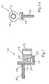
- a frame strip 10 according to the invention can be seen, this has at least one bore 12 for receiving a bolt, not shown here, for example a wing band leads stored.
- the frame band 10 has a firmly connectable to a frame, not shown here Slide 16 on.
- This slider 16 is of a shell part 18 at least partially encompassed and moves relatively to the shell part 18 by means of a height adjustment device 14th
- the height adjustment device 14 is arranged in the slider 16 Adjustment device 20 with the shell part 18 in Contact stands. Via a contact point 22 may be a change in position of the shell part 18 with respect to the slider 16 steplessly be set.
- the adjusting device 20 in the form of a rotatable mounted eccentric 24 executed.
- a receptacle 34 is provided in the example a support pin 36 is screwed.
- the first embodiment of the frame strip 10 according to the invention is in this case designed as a hinge band. It can in particular as so-called Aufschraubband on a frame, not shown here be attached.
- the slider 16 in addition still a surface to be fixed on the frame Element.
- Screw 26 includes.
- the screw 26 is by means of a thread 46 supported on the fixedly connected to the frame slide 16.
- the screw 26 is a grub screw is executed with a hexagon.
- a securing element 28 which is fixed to the shell part, is supported 18 is linked, forming a common Contact point 22 from.
- the fuse element passes through the Slider 16, in the penetration area of the fuse element 28 has a slot 48.
- the slider 16 is sized that he at the extreme positions of the height adjustment device 14 terminates flush with the shell part 18 at most.
- Frame 34 shots are introduced, which are to attach serve by support pins 36.
- the slider 16 and the shell part 18 also have recesses 38, which are for recording serve not shown here fastening means 40 to after height adjustment together a long term Accurate fixation on the frame to create.
- an element 42 of the Shell part 18 between frame and slide 16 is arranged.
- the element 42nd arranged recesses 38 formed in the form of slots.
- a cap 50 underside in the Bore 12 are introduced to the height adjustment 14 cover.
- a socket 32 in the Bore 12 for supporting a hinge pin not shown here be provided.
- This has a collar 54, on its surface adherent and low friction this is not shown wing band rests.
- the collar 54 can also the construction-related, for sliding displacement of the slider Cover 16 necessary for height adjustment gap 52.
- the collar 54 has this one suitable contour in the area between axle mount and slide 16 and the shell part 18 on.
- the fuse element 28 is in this embodiment Frame side introduced into the shell part 18. Of the Slider 16 and the shell part 18 are band-top strip-shaped educated. The strip-shaped part of the frame band 10 serves as a mounting strip.
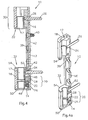
- FIG. 3 shows the schematic cross section of a third Embodiment of a frame strip 10 according to the invention.
- This three-part frame band 10 has an abutment 30, which is attached to the top shell of the shell part 18. Performs by a firm connection with the shell part 18 the anvil 30, which has a coaxial bore 12 to the band upper side Guide a hinge pin, not shown here serves to be carried out via the height adjustment device 14 Position change of the shell part 18 with.
- the slider 16 is in this third embodiment between the frame, not shown, and the shell part 18 arranged.
- the slider 16 has recesses 38 in the form from oblong holes to when moving the shell part 18 a penetration of the fastener 40 in the To enable frames not shown here.
- the fastener 40 may be shown next to the one shown here Also screw any other load-bearing fastener be.
- the abutment 30 in addition to the shown here assembly on the shell part 18, for example be attached by simply plugging the shell part 18.
- FIG. 4 is the cross section of a fourth embodiment a frame strip 10 according to the invention shown.
- This three-piece frame band 10 has a shell part 18 movably guided slide 16.
- the shell part 18 and the anvil 30 are made in one piece.
- the for stepless change in position of the shell part 18 with respect to the slide 16 provided height adjustment device 14th has an adjusting device 20 slide side and a fuse element on the shell part side.
- In the slide 16 are in addition to the receptacle 34 for attachment of the support pins 36, the allow fixation with the frame not shown here, a thread 46 introduced below the band. This serves to support the screw 26, the end of the screw the contact point 22 with the fuse element 28 in contact stands.
- the fuse element 28 is fixed to the frame side Shell part 18 is connected and protrudes into a valve 16 provided in the Slot 48.
- a simple rotation of the Screw 26 is a stepless change in position of the shell part 18 with respect to the fixed slide 16 is reached.
- the executed in the form of a Traumschraubance element 42 of the Shell part 18 also has recesses 38 in the form of slots in order to reach through fastening means 40, the one load-transmitting, solid connection of slide 16 and shell part 18 with the frame not shown here.
- the recess 38 in the slide can be designed as a reduction, for example, the head to receive the fastener 40 positively.
- the slider 16 As especially good in the perspective side view of the fourth embodiment in Fig.4a, surrounds the shell part 18, the slider 16.
- the slider 16 is here so that it is at the extreme positions of the height adjustment device 14 with the shell part 18 at most flush concludes.
- Bandobertagen and banduntercloth are slides 16 and shell member 18 formed such that they in combination form the bore 12.
- the jacks 32 In the bore 12 are sockets 32 introduced to receive a not shown here Serving hinge pin.
- the jacks 32 each have a contoured Collar 54 on.
- the collar 54 is supported on the shell part 18 off.
- the collar 54 is in particular designed such that he has a height adjustment of the frame band 10th necessary gap 52 between bore 12 and slide 16 covers.
- the bore 12 and the height adjustment device 14th are covered by the cap 50.
- the slide 16 and the shell part 18 are injection molded or extruded part mass-produced inexpensively. Depending on the application and location, they are made of metal, Plastic or a combination thereof.
- the height adjustment device 14 Upon actuation of the height adjustment device 14 is the Location of one located between the sockets 32 not here shown wing bands continuously positioned relative to the frame. This changes a distance between the collar 54 and the rotatably mounted thereon band part Not.
- a lateral adjustment device 56 is provided, which has two adjusting elements 58 in threaded holes 60 of the slider 16 sit and as adjusting 62nd are formed. In the assembled state are between the inner wall 64 of the shell part 18 and the slider 16 two plungers 66, which act as coil springs on the Shafts of the adjusting screws 62 sit.
- the adjusting screws 62 can each by a Slot 68 in the shell part 18 for lateral adjustment of the shell part 18 are rotated from the outside, whereby by the Slots 68 is simultaneously ensured that the shell part 18 adjusted relative to the slider 16 in its altitude can be without access to the adjustment screws 62 prevent.
- the heads of the adjusting screws 62 are supported while on the shell part 18 in the slots 68 from.
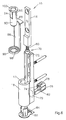
- FIG. 1 is a perspective View of a two-part frame band 10, wherein the shell part 18 relative to the slider 16 in the manner of a spindle carriage can be moved in height.
- Serves an adjusting screw 70 whose threaded portion in a frontal Thread on the lower part of the slider 16 is seated.
- Head 72 of the adjusting screw 70 is in mounted Condition of the frame band 10 in a cavity 74 of a slide-in element 76, the twist-proof and self-locking in one Opening 79 is seated on the back of the shell part 18.
- the insertion element 76 has on the top of the cavity 74th a U-shaped recess 78 which extends from the shaft 80 of the adjusting screw 70 is taken.
- the height of the cavity 74 corresponds approximately to the thickness of the head 72 of the adjusting screw 70th
- the adjusting screw 70 in the assembled state and thus the shell part 18 in its altitude relatively to adjust the slider 16, has the insertion element 76 on a through-hole 82.
- the hole 84 serves in the cap 50.
- a cap 86 which in the assembled state of compassionbandes 10 the slider 16 and the upper part of the Shell part 18 covers.
- the cap 86 is supported with a nose 88 on the upper end side of the shell part From 18 and lies with a retaining ring 90 on the bore 12 of the Shell part 18 on.
- the retaining ring 90 serves to receive a Frame tape socket 92, in turn, for receiving the not shown hinge pin of the wing band is used.
- the Frame strap bushing 92 has on its wall in each case extending in its longitudinal direction, a first projection 94 and a second projection 96, which in opposite recesses 98 engage the retaining ring 90 and the bore 12, so that the frame band socket 92 twist and tilt safe in the retaining ring 90 and the bore 12 is seated.
- the frame band socket 92 formed and changed eccentrically in total their distance in the direction of the wing plane when around 180 ° twisted into the retaining ring 90 and the bore 12 is inserted becomes. This is indicated by the plus and minus signs symbolizes the top of the bushing ring 100.
Landscapes
- Engineering & Computer Science (AREA)
- Mechanical Engineering (AREA)
- Hinges (AREA)
- Clamps And Clips (AREA)
- Body Structure For Vehicles (AREA)
- Buckles (AREA)
- Automobile Manufacture Line, Endless Track Vehicle, Trailer (AREA)
Priority Applications (1)
| Application Number | Priority Date | Filing Date | Title |
|---|---|---|---|
| PL05005828T PL1602794T3 (pl) | 2004-06-03 | 2005-03-17 | Zawias ościeżnicy |
Applications Claiming Priority (2)
| Application Number | Priority Date | Filing Date | Title |
|---|---|---|---|
| DE202004008852U | 2004-06-03 | ||
| DE202004008852 | 2004-06-03 |
Publications (3)
| Publication Number | Publication Date |
|---|---|
| EP1602794A2 true EP1602794A2 (fr) | 2005-12-07 |
| EP1602794A3 EP1602794A3 (fr) | 2010-02-17 |
| EP1602794B1 EP1602794B1 (fr) | 2013-01-23 |
Family
ID=34934328
Family Applications (1)
| Application Number | Title | Priority Date | Filing Date |
|---|---|---|---|
| EP05005828A Expired - Lifetime EP1602794B1 (fr) | 2004-06-03 | 2005-03-17 | Ferrure de cadre |
Country Status (3)
| Country | Link |
|---|---|
| EP (1) | EP1602794B1 (fr) |
| ES (1) | ES2404306T3 (fr) |
| PL (1) | PL1602794T3 (fr) |
Cited By (5)
| Publication number | Priority date | Publication date | Assignee | Title |
|---|---|---|---|---|
| CN102287102A (zh) * | 2010-06-15 | 2011-12-21 | 家居安全组有限公司 | 铰链 |
| EP2342408B1 (fr) * | 2008-10-28 | 2014-01-08 | Omf S.R.L. | Dispositif de reglage pour charnière invisible et charnière invisible comprenant ledit dispositif de reglage |
| ITVI20130101A1 (it) * | 2013-04-12 | 2014-10-13 | In & Tec Srl | Cerniera per la movimentazione girevole di una porta |
| WO2014167546A3 (fr) * | 2013-04-12 | 2015-03-12 | In & Tec S.R.L. | Charnière pouvant être cachée pour le mouvement de rotation régulé d'une porte, en particulier d'une porte renforcée |
| EP2808474B1 (fr) | 2013-05-27 | 2016-04-20 | Gang Gwo Industrial Co., Ltd | Charnière hydraulique pour porte en verre |
Family Cites Families (8)
| Publication number | Priority date | Publication date | Assignee | Title |
|---|---|---|---|---|
| AT371207B (de) * | 1976-12-07 | 1983-06-10 | Mayer & Co Riegel Beschlag | Einstellvorrichtung fuer ein ecklager oder scherenlager von fenster- oder tuerfluegeln |
| IT1237830B (it) * | 1989-11-21 | 1993-06-18 | Roberto Mariani | Dispositivo per l'attacco regolabile di un'anta di armadio a un braccio di supporto. |
| DE9215565U1 (de) * | 1992-11-16 | 1994-03-17 | Hahn Gmbh & Co Kg Dr | Band für Türen, Fenster u.dgl. |
| US5788351A (en) * | 1996-05-30 | 1998-08-04 | Prunty; Jeffrey L. | Cam for vertical adjustment of appliance doors |
| FR2829792B3 (fr) * | 2001-09-14 | 2003-09-05 | Alias S R L | Charniere invisible reglable pour portes, fermetures ou analogues |
| GB2383081B (en) * | 2001-12-13 | 2005-06-01 | J K Furnex Ltd | Hinges |
| DE10212476B4 (de) * | 2002-03-20 | 2004-06-17 | Niemann, Hans Dieter | Verstelleinrichtung eines Drehbandes von Türen oder Fenstern |
| DE10301054B3 (de) * | 2003-01-14 | 2004-07-15 | Zoltan Anton Kiefer | Scharnier |
-
2005
- 2005-03-17 PL PL05005828T patent/PL1602794T3/pl unknown
- 2005-03-17 ES ES05005828T patent/ES2404306T3/es not_active Expired - Lifetime
- 2005-03-17 EP EP05005828A patent/EP1602794B1/fr not_active Expired - Lifetime
Cited By (10)
| Publication number | Priority date | Publication date | Assignee | Title |
|---|---|---|---|---|
| EP2342408B1 (fr) * | 2008-10-28 | 2014-01-08 | Omf S.R.L. | Dispositif de reglage pour charnière invisible et charnière invisible comprenant ledit dispositif de reglage |
| CN102287102A (zh) * | 2010-06-15 | 2011-12-21 | 家居安全组有限公司 | 铰链 |
| GB2481371A (en) * | 2010-06-15 | 2011-12-28 | Grouphomesafe Ltd | Adjustable hinge |
| GB2481371B (en) * | 2010-06-15 | 2016-06-08 | Grouphomesafe Ltd | Hinges |
| CN102287102B (zh) * | 2010-06-15 | 2016-08-03 | 时代家居安全有限公司 | 铰链 |
| ITVI20130101A1 (it) * | 2013-04-12 | 2014-10-13 | In & Tec Srl | Cerniera per la movimentazione girevole di una porta |
| WO2014167546A3 (fr) * | 2013-04-12 | 2015-03-12 | In & Tec S.R.L. | Charnière pouvant être cachée pour le mouvement de rotation régulé d'une porte, en particulier d'une porte renforcée |
| EP3306022A1 (fr) * | 2013-04-12 | 2018-04-11 | In & Tec S.r.l. | Charnière dissimulée pour le mouvement rotatif contrôlé d'une porte, en particulier d'une porte renforcée |
| EA030890B1 (ru) * | 2013-04-12 | 2018-10-31 | Ин Энд Тек С.Р.Л. | Скрытая петля для регулируемого вращательного движения двери, в частности армированной двери |
| EP2808474B1 (fr) | 2013-05-27 | 2016-04-20 | Gang Gwo Industrial Co., Ltd | Charnière hydraulique pour porte en verre |
Also Published As
| Publication number | Publication date |
|---|---|
| EP1602794B1 (fr) | 2013-01-23 |
| ES2404306T3 (es) | 2013-05-27 |
| PL1602794T3 (pl) | 2013-06-28 |
| EP1602794A3 (fr) | 2010-02-17 |
Similar Documents
| Publication | Publication Date | Title |
|---|---|---|
| DE69312588T2 (de) | Dünne Ausziehführungsgarnitur mit Seitenversatz und Begleitrolle | |
| EP0285229B2 (fr) | Charnière réglable, en particulier pour portes | |
| EP2546438B1 (fr) | Dispositif prévu pour montage mobile dans une partie de ferrure prévue avec une gorge de ferrure dotée d'une contre-dépouille | |
| WO2008125318A2 (fr) | Système de guidage de tiges réglable | |
| EP1602794B1 (fr) | Ferrure de cadre | |
| DE202016101091U1 (de) | Türverriegelung | |
| EP1215357B1 (fr) | Arrangement de charnière pour portes, fenêtres ou similaires | |
| DE29503024U1 (de) | Flügellager | |
| DE202008016071U1 (de) | Band zur scharniergelenkigen Verbindung eines Flügels an einem Rahmen | |
| DE102008036151A1 (de) | Scharnierband mit einer Unterkonstruktion zur Befestigung an einem Türblatt | |
| DE102020121334B3 (de) | Türband zur schwenkbaren Lagerung eines Türflügels in einem Rahmen | |
| EP0861953A1 (fr) | Poignée de manoeuvre | |
| DE202004008854U1 (de) | Rahmenband | |
| EP0930411B1 (fr) | Penture de porte ou de fenêtre | |
| EP1223275B1 (fr) | Penture pour portes ou fenêtres | |
| EP3704337B1 (fr) | Pièce de bande | |
| DE102020121336B3 (de) | Türband zur schwenkbaren Lagerung eines Türflügels in einem Rahmen | |
| DE19918283B4 (de) | Tür- oder Fensterdrehband | |
| DE20105545U1 (de) | Band für Türen, Fenster o.dgl. | |
| EP2896772B1 (fr) | Partie de bande d'une bande destinée à la fixation articulée d'un battant sur un cadre | |
| DE202009005027U1 (de) | Band zur schwenkbaren Verbindung eines Flügels an einem Rahmen | |
| EP1528203A2 (fr) | Charnière pour portes, fenêtres ou similaire | |
| DE102017202727B4 (de) | Verdeckt angeordneter Beschlag für Fenster, Türen oder dergleichen | |
| DE3301509C2 (de) | Ecklager für Drehkippflügel von Fenstern, Türen od.dgl. | |
| DE9214372U1 (de) | Mehrdimensional einstellbares Scharnier für Türen o.dgl. |
Legal Events
| Date | Code | Title | Description |
|---|---|---|---|
| PUAI | Public reference made under article 153(3) epc to a published international application that has entered the european phase |
Free format text: ORIGINAL CODE: 0009012 |
|
| AK | Designated contracting states |
Kind code of ref document: A2 Designated state(s): AT BE BG CH CY CZ DE DK EE ES FI FR GB GR HU IE IS IT LI LT LU MC NL PL PT RO SE SI SK TR |
|
| AX | Request for extension of the european patent |
Extension state: AL BA HR LV MK YU |
|
| PUAL | Search report despatched |
Free format text: ORIGINAL CODE: 0009013 |
|
| AK | Designated contracting states |
Kind code of ref document: A3 Designated state(s): AT BE BG CH CY CZ DE DK EE ES FI FR GB GR HU IE IS IT LI LT LU MC NL PL PT RO SE SI SK TR |
|
| AX | Request for extension of the european patent |
Extension state: AL BA HR LV MK YU |
|
| 17P | Request for examination filed |
Effective date: 20100610 |
|
| AKX | Designation fees paid |
Designated state(s): AT BE BG CH CY CZ DE DK EE ES FI FR GB GR HU IE IS IT LI LT LU MC NL PL PT RO SE SI SK TR |
|
| RAP1 | Party data changed (applicant data changed or rights of an application transferred) |
Owner name: ROTO GLUSKE-BKV GMBH |
|
| 17Q | First examination report despatched |
Effective date: 20110629 |
|
| GRAP | Despatch of communication of intention to grant a patent |
Free format text: ORIGINAL CODE: EPIDOSNIGR1 |
|
| GRAS | Grant fee paid |
Free format text: ORIGINAL CODE: EPIDOSNIGR3 |
|
| GRAA | (expected) grant |
Free format text: ORIGINAL CODE: 0009210 |
|
| AK | Designated contracting states |
Kind code of ref document: B1 Designated state(s): AT BE BG CH CY CZ DE DK EE ES FI FR GB GR HU IE IS IT LI LT LU MC NL PL PT RO SE SI SK TR |
|
| REG | Reference to a national code |
Ref country code: GB Ref legal event code: FG4D Free format text: NOT ENGLISH |
|
| REG | Reference to a national code |
Ref country code: CH Ref legal event code: EP |
|
| REG | Reference to a national code |
Ref country code: CH Ref legal event code: EP Ref country code: AT Ref legal event code: REF Ref document number: 595089 Country of ref document: AT Kind code of ref document: T Effective date: 20130215 |
|
| REG | Reference to a national code |
Ref country code: IE Ref legal event code: FG4D Free format text: LANGUAGE OF EP DOCUMENT: GERMAN |
|
| REG | Reference to a national code |
Ref country code: DE Ref legal event code: R096 Ref document number: 502005013427 Country of ref document: DE Effective date: 20130321 |
|
| REG | Reference to a national code |
Ref country code: ES Ref legal event code: FG2A Ref document number: 2404306 Country of ref document: ES Kind code of ref document: T3 Effective date: 20130527 |
|
| REG | Reference to a national code |
Ref country code: LT Ref legal event code: MG4D |
|
| REG | Reference to a national code |
Ref country code: NL Ref legal event code: VDEP Effective date: 20130123 |
|
| REG | Reference to a national code |
Ref country code: PL Ref legal event code: T3 |
|
| PG25 | Lapsed in a contracting state [announced via postgrant information from national office to epo] |
Ref country code: IS Free format text: LAPSE BECAUSE OF FAILURE TO SUBMIT A TRANSLATION OF THE DESCRIPTION OR TO PAY THE FEE WITHIN THE PRESCRIBED TIME-LIMIT Effective date: 20130523 Ref country code: BG Free format text: LAPSE BECAUSE OF FAILURE TO SUBMIT A TRANSLATION OF THE DESCRIPTION OR TO PAY THE FEE WITHIN THE PRESCRIBED TIME-LIMIT Effective date: 20130423 Ref country code: SE Free format text: LAPSE BECAUSE OF FAILURE TO SUBMIT A TRANSLATION OF THE DESCRIPTION OR TO PAY THE FEE WITHIN THE PRESCRIBED TIME-LIMIT Effective date: 20130123 Ref country code: LT Free format text: LAPSE BECAUSE OF FAILURE TO SUBMIT A TRANSLATION OF THE DESCRIPTION OR TO PAY THE FEE WITHIN THE PRESCRIBED TIME-LIMIT Effective date: 20130123 Ref country code: CY Free format text: LAPSE BECAUSE OF FAILURE TO SUBMIT A TRANSLATION OF THE DESCRIPTION OR TO PAY THE FEE WITHIN THE PRESCRIBED TIME-LIMIT Effective date: 20130123 |
|
| PG25 | Lapsed in a contracting state [announced via postgrant information from national office to epo] |
Ref country code: PT Free format text: LAPSE BECAUSE OF FAILURE TO SUBMIT A TRANSLATION OF THE DESCRIPTION OR TO PAY THE FEE WITHIN THE PRESCRIBED TIME-LIMIT Effective date: 20130523 Ref country code: GR Free format text: LAPSE BECAUSE OF FAILURE TO SUBMIT A TRANSLATION OF THE DESCRIPTION OR TO PAY THE FEE WITHIN THE PRESCRIBED TIME-LIMIT Effective date: 20130424 Ref country code: FI Free format text: LAPSE BECAUSE OF FAILURE TO SUBMIT A TRANSLATION OF THE DESCRIPTION OR TO PAY THE FEE WITHIN THE PRESCRIBED TIME-LIMIT Effective date: 20130123 Ref country code: SI Free format text: LAPSE BECAUSE OF FAILURE TO SUBMIT A TRANSLATION OF THE DESCRIPTION OR TO PAY THE FEE WITHIN THE PRESCRIBED TIME-LIMIT Effective date: 20130123 Ref country code: NL Free format text: LAPSE BECAUSE OF FAILURE TO SUBMIT A TRANSLATION OF THE DESCRIPTION OR TO PAY THE FEE WITHIN THE PRESCRIBED TIME-LIMIT Effective date: 20130123 |
|
| BERE | Be: lapsed |
Owner name: ROTO GLUSKE-BKV G.M.B.H. Effective date: 20130331 |
|
| PG25 | Lapsed in a contracting state [announced via postgrant information from national office to epo] |
Ref country code: RO Free format text: LAPSE BECAUSE OF FAILURE TO SUBMIT A TRANSLATION OF THE DESCRIPTION OR TO PAY THE FEE WITHIN THE PRESCRIBED TIME-LIMIT Effective date: 20130123 Ref country code: DK Free format text: LAPSE BECAUSE OF FAILURE TO SUBMIT A TRANSLATION OF THE DESCRIPTION OR TO PAY THE FEE WITHIN THE PRESCRIBED TIME-LIMIT Effective date: 20130123 Ref country code: EE Free format text: LAPSE BECAUSE OF FAILURE TO SUBMIT A TRANSLATION OF THE DESCRIPTION OR TO PAY THE FEE WITHIN THE PRESCRIBED TIME-LIMIT Effective date: 20130123 Ref country code: SK Free format text: LAPSE BECAUSE OF FAILURE TO SUBMIT A TRANSLATION OF THE DESCRIPTION OR TO PAY THE FEE WITHIN THE PRESCRIBED TIME-LIMIT Effective date: 20130123 Ref country code: CZ Free format text: LAPSE BECAUSE OF FAILURE TO SUBMIT A TRANSLATION OF THE DESCRIPTION OR TO PAY THE FEE WITHIN THE PRESCRIBED TIME-LIMIT Effective date: 20130123 Ref country code: MC Free format text: LAPSE BECAUSE OF NON-PAYMENT OF DUE FEES Effective date: 20130331 |
|
| REG | Reference to a national code |
Ref country code: CH Ref legal event code: PL |
|
| PLBE | No opposition filed within time limit |
Free format text: ORIGINAL CODE: 0009261 |
|
| STAA | Information on the status of an ep patent application or granted ep patent |
Free format text: STATUS: NO OPPOSITION FILED WITHIN TIME LIMIT |
|
| GBPC | Gb: european patent ceased through non-payment of renewal fee |
Effective date: 20130423 |
|
| 26N | No opposition filed |
Effective date: 20131024 |
|
| REG | Reference to a national code |
Ref country code: IE Ref legal event code: MM4A |
|
| PG25 | Lapsed in a contracting state [announced via postgrant information from national office to epo] |
Ref country code: IE Free format text: LAPSE BECAUSE OF NON-PAYMENT OF DUE FEES Effective date: 20130317 Ref country code: BE Free format text: LAPSE BECAUSE OF NON-PAYMENT OF DUE FEES Effective date: 20130331 Ref country code: CH Free format text: LAPSE BECAUSE OF NON-PAYMENT OF DUE FEES Effective date: 20130331 Ref country code: LI Free format text: LAPSE BECAUSE OF NON-PAYMENT OF DUE FEES Effective date: 20130331 Ref country code: GB Free format text: LAPSE BECAUSE OF NON-PAYMENT OF DUE FEES Effective date: 20130423 |
|
| REG | Reference to a national code |
Ref country code: DE Ref legal event code: R097 Ref document number: 502005013427 Country of ref document: DE Effective date: 20131024 |
|
| REG | Reference to a national code |
Ref country code: HU Ref legal event code: AG4A |
|
| REG | Reference to a national code |
Ref country code: AT Ref legal event code: MM01 Ref document number: 595089 Country of ref document: AT Kind code of ref document: T Effective date: 20130317 |
|
| PG25 | Lapsed in a contracting state [announced via postgrant information from national office to epo] |
Ref country code: AT Free format text: LAPSE BECAUSE OF NON-PAYMENT OF DUE FEES Effective date: 20130317 |
|
| PG25 | Lapsed in a contracting state [announced via postgrant information from national office to epo] |
Ref country code: TR Free format text: LAPSE BECAUSE OF FAILURE TO SUBMIT A TRANSLATION OF THE DESCRIPTION OR TO PAY THE FEE WITHIN THE PRESCRIBED TIME-LIMIT Effective date: 20130123 |
|
| PG25 | Lapsed in a contracting state [announced via postgrant information from national office to epo] |
Ref country code: LU Free format text: LAPSE BECAUSE OF NON-PAYMENT OF DUE FEES Effective date: 20130317 |
|
| REG | Reference to a national code |
Ref country code: FR Ref legal event code: PLFP Year of fee payment: 12 |
|
| REG | Reference to a national code |
Ref country code: FR Ref legal event code: PLFP Year of fee payment: 13 |
|
| REG | Reference to a national code |
Ref country code: FR Ref legal event code: PLFP Year of fee payment: 14 |
|
| REG | Reference to a national code |
Ref country code: DE Ref legal event code: R082 Ref document number: 502005013427 Country of ref document: DE Representative=s name: KUEHNEL, MICHAEL, DIPL.-CHEM. DR. RER. NAT., DE |
|
| PGFP | Annual fee paid to national office [announced via postgrant information from national office to epo] |
Ref country code: HU Payment date: 20210309 Year of fee payment: 17 Ref country code: PL Payment date: 20210305 Year of fee payment: 17 Ref country code: DE Payment date: 20210323 Year of fee payment: 17 |
|
| PGFP | Annual fee paid to national office [announced via postgrant information from national office to epo] |
Ref country code: FR Payment date: 20220322 Year of fee payment: 18 |
|
| PGFP | Annual fee paid to national office [announced via postgrant information from national office to epo] |
Ref country code: IT Payment date: 20220331 Year of fee payment: 18 Ref country code: ES Payment date: 20220420 Year of fee payment: 18 |
|
| REG | Reference to a national code |
Ref country code: DE Ref legal event code: R119 Ref document number: 502005013427 Country of ref document: DE |
|
| PG25 | Lapsed in a contracting state [announced via postgrant information from national office to epo] |
Ref country code: HU Free format text: LAPSE BECAUSE OF NON-PAYMENT OF DUE FEES Effective date: 20220318 Ref country code: DE Free format text: LAPSE BECAUSE OF NON-PAYMENT OF DUE FEES Effective date: 20221001 |
|
| PG25 | Lapsed in a contracting state [announced via postgrant information from national office to epo] |
Ref country code: PL Free format text: LAPSE BECAUSE OF NON-PAYMENT OF DUE FEES Effective date: 20220317 |
|
| PG25 | Lapsed in a contracting state [announced via postgrant information from national office to epo] |
Ref country code: FR Free format text: LAPSE BECAUSE OF NON-PAYMENT OF DUE FEES Effective date: 20230331 |
|
| PG25 | Lapsed in a contracting state [announced via postgrant information from national office to epo] |
Ref country code: IT Free format text: LAPSE BECAUSE OF NON-PAYMENT OF DUE FEES Effective date: 20230317 |
|
| REG | Reference to a national code |
Ref country code: ES Ref legal event code: FD2A Effective date: 20240430 |
|
| PG25 | Lapsed in a contracting state [announced via postgrant information from national office to epo] |
Ref country code: ES Free format text: LAPSE BECAUSE OF NON-PAYMENT OF DUE FEES Effective date: 20230318 |
|
| PG25 | Lapsed in a contracting state [announced via postgrant information from national office to epo] |
Ref country code: ES Free format text: LAPSE BECAUSE OF NON-PAYMENT OF DUE FEES Effective date: 20230318 |