EP1602914A2 - Dispositif et méthode de test de fixations de composants - Google Patents
Dispositif et méthode de test de fixations de composants Download PDFInfo
- Publication number
- EP1602914A2 EP1602914A2 EP05252751A EP05252751A EP1602914A2 EP 1602914 A2 EP1602914 A2 EP 1602914A2 EP 05252751 A EP05252751 A EP 05252751A EP 05252751 A EP05252751 A EP 05252751A EP 1602914 A2 EP1602914 A2 EP 1602914A2
- Authority
- EP
- European Patent Office
- Prior art keywords
- component
- shaped
- load
- edge
- shaped slot
- Prior art date
- Legal status (The legal status is an assumption and is not a legal conclusion. Google has not performed a legal analysis and makes no representation as to the accuracy of the status listed.)
- Granted
Links
Images


Classifications
-
- G—PHYSICS
- G01—MEASURING; TESTING
- G01N—INVESTIGATING OR ANALYSING MATERIALS BY DETERMINING THEIR CHEMICAL OR PHYSICAL PROPERTIES
- G01N3/00—Investigating strength properties of solid materials by application of mechanical stress
- G01N3/32—Investigating strength properties of solid materials by application of mechanical stress by applying repeated or pulsating forces
-
- G—PHYSICS
- G01—MEASURING; TESTING
- G01N—INVESTIGATING OR ANALYSING MATERIALS BY DETERMINING THEIR CHEMICAL OR PHYSICAL PROPERTIES
- G01N3/00—Investigating strength properties of solid materials by application of mechanical stress
- G01N3/02—Details
- G01N3/04—Chucks
-
- G—PHYSICS
- G01—MEASURING; TESTING
- G01N—INVESTIGATING OR ANALYSING MATERIALS BY DETERMINING THEIR CHEMICAL OR PHYSICAL PROPERTIES
- G01N2203/00—Investigating strength properties of solid materials by application of mechanical stress
- G01N2203/02—Details not specific for a particular testing method
- G01N2203/022—Environment of the test
- G01N2203/0222—Temperature
- G01N2203/0226—High temperature; Heating means
-
- G—PHYSICS
- G01—MEASURING; TESTING
- G01N—INVESTIGATING OR ANALYSING MATERIALS BY DETERMINING THEIR CHEMICAL OR PHYSICAL PROPERTIES
- G01N2203/00—Investigating strength properties of solid materials by application of mechanical stress
- G01N2203/02—Details not specific for a particular testing method
- G01N2203/026—Specifications of the specimen
- G01N2203/0262—Shape of the specimen
- G01N2203/027—Specimens with holes or notches
Definitions
- the present invention relates to an apparatus and a method for testing attachment features of components and in particular to an apparatus and a method for testing attachment features, e.g. dovetails or firtrees, of compressor blades/discs or turbine blades/discs.
- attachment features e.g. dovetails or firtrees
- the attachment features of components e.g. the dovetail roots, or firtree roots, of rotor blades and correspondingly shaped slots in a rotor, suffer from fretting fatigue.
- This fretting fatigue in the attachment features may lead to the formation of cracking in the attachment features, which limits the useful life of the components, e.g. the rotor blades or rotor discs. Once cracking has started in the attachment features it is necessary to replace the rotor blades or discs.
- the present invention seeks to provide a novel apparatus and method for testing attachment features of components.
- the present invention provides an apparatus for testing attachment features of components comprising a first member having a first end, a second end, a first edge and a second edge, the first edge having a first shaped slot to receive a first component, the first component having an attachment feature correspondingly shaped to fit the first shaped slot, the first end of the first member having flanges extending laterally away from the first member and the second end of the first member having flanges extending laterally away from the first member such that the first member is substantially H-shaped in cross-section, first load means to apply a load on the first component and second load means to apply a load on the first member substantially in the opposite direction to the load on the first component.
- the second edge having a second shaped slot to receive a second component
- the second component having an attachment feature correspondingly shaped to fit the second shaped slot
- the second load means to apply a load on the second component substantially in the opposite direction to the load on the first component
- the first loads may be arranged to apply tension and/or torsion loads.
- the second load means may be arranged to apply tension and/or torsion loads.
- the flanges at the first end of the first member extend substantially perpendicularly from the first member.
- the flanges at the second end of the first member extend substantially perpendicularly from the first member.
- the first shaped slot in the first edge of the first member is firtree shaped in cross-section.
- the first shaped slot in the first edge of the first member is dovetail shaped in cross-section.
- the second shaped slot in the second edge of the first member is firtree shaped in cross-section.
- the second shaped slot in the second edge of the first member is dovetail shaped in cross-section.
- the first member having support members extending laterally away from the first member, the support members extending between and being secured to the flanges at the first and second ends of the first member, the support members extending between the first and second shaped slots.
- a vibration means is provided to vibrate the first member, the first component and the second component.
- a heating means is provided to heat the first member, the first component and the second component.
- the first component is a compressor blade, a fan blade or a turbine blade.
- the second component is a compressor blade, a fan blade or a turbine blade.
- the present invention provides a method of testing attachment features of components comprising a first member having a first end, a second end, a first edge and a second edge, the first edge having a first shaped slot to receive a first component, the first component having an attachment feature correspondingly shaped to fit the first shaped slot, the first end of the first member having flanges extending laterally away from the first member and the second end of the first member having flanges extending laterally away from the first member such that the first member is substantially H-shaped in cross-section, applying a load on the first component and applying a load on the first member substantially in the opposite direction to the load on the first component.
- the second edge having a second shaped slot to receive a second component
- the second component having an attachment feature correspondingly shaped to fit the second shaped slot, and applying a load on the second component substantially in the opposite direction to the load on the first component.
- the load applied on the first component may be tension and/or torsion loads.
- the load applied on the second component may be tension and/or torsion loads.
- the flanges at the first end of the first member extend substantially perpendicularly from the first member.
- the flanges at the second end of the first member extend substantially perpendicularly from the first member.
- the first shaped slot in the first edge of the first member is firtree shaped in cross-section.
- the first shaped slot in the first edge of the first member is dovetail shaped in cross-section.
- the second shaped slot in the second edge of the first member is firtree shaped in cross-section.
- the second shaped slot in the second edge of the first member is dovetail shaped in cross-section.
- the first member having support members extending laterally away from the first member, the support members extending between and being secured to the flanges at the first and second ends of the first member, the support members extending between the first and second shaped slots.
- the method comprises vibrating the first member, the first component and the second component.
- the method comprises heating the first member, the first component and the second component.
- the first component is a compressor blade, a fan blade or a turbine blade.
- the second component is a compressor blade, a fan blade or a turbine blade.
- the apparatus 10 comprises a first member 16, which has a first end 18, a second end 20, a first edge 22 and a second edge 24.
- the first edge 22 has a first shaped slot 26 to receive the first component 12 and the second edge 24 has a second shaped slot 28 to receive the second component 14.
- the first component 12 has an attachment feature 30 correspondingly shaped to fit the first shaped slot 26 and the second component 14 has an attachment feature 32 correspondingly shaped to fit the second shaped slot 28.
- the first end 18 of the first member 16 has flanges 34 and 36 extending laterally away from the first member 16 and the second end 20 of the first member 16 has flanges 38 and 40 extending laterally away from the first member 16 such that the first member 16 is substantially H-shaped in cross-section.
- a first load means 42 is secured to the first component 12 and is arranged to apply a load on the first component 12.
- a second load means 44 is secured to the second component 14 and is arranged to apply a load on the second component 14 substantially in the opposite direction to the load on the first component 12.
- the first and second load means 42 and 44 are arranged to apply a tension load on the first and second components 12 and 14 and the first member 16.
- the first and second load means 42 and 44 may comprise a conventional load cell capable of applying tensile loads of up to several hundred kN, e.g. 200kN.
- the flanges 34 and 36 at the first end 18 of the first member 16 extend substantially perpendicularly from the first member 16.
- the flanges 38 and 40 at the second end 20 of the first member 16 extend substantially perpendicularly from the first member 16.
- the first shaped slot 26 in the first edge 22 of the first member 16 is firtree shaped in cross-section.
- the attachment feature 30 of the first component 12 is firtree shaped in cross-section.
- the first shaped slot 26 in the first edge 22 of the first member 16 and the attachment feature 30 of the first component 12 may be dovetail shaped in cross-section.
- the second shaped slot 28 in the second edge 24 of the first member 16 is firtree shaped in cross-section.
- the attachment feature 32 of the second component 14 is firtree shaped in cross-section.
- the second shaped slot 28 in the second edge 24 of the first member 16 and the attachment feature 32 of the second component 14 may be dovetail shaped in cross-section.
- the first member 16 has first and second support members 45 and 46 extending laterally away from the first member 16.
- the first support member 45 extends between and is secured to the flanges 34 and 38 at the first and second ends 18 and 20 respectively of the first member 16.
- the second support member 46 extends between and is secured to the flanges 36 and 40 at the first and second ends 18 and 20 respectively of the first member 16.
- the support members 45 and 46 extend between the first and second shaped slots 26 and 28.
- a vibration means 48 is provided to vibrate the first member 16, the first component 12 and the second component 14.
- the vibration means 48 for example comprises a piezoelectric transducer, a magnetostrictive transducer or mechanical shaker or other suitable device acoustically coupled to the first component 12 and/or the second component 14.
- a heating means 50 is provided to heat the first member 16, the first component 12 and the second component 14, if testing is required to be tested at higher temperatures to simulate thermal gradients.
- the first component 12 may be a compressor blade, a fan blade or a turbine blade.
- the second component 14 may be a compressor blade, a fan blade or a turbine blade.
- the processor 58 also controls the first load means 42, the second load means 44, the heating means 50 and the vibration means 58.
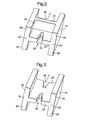
- first member 116 for testing attachment features of components 12, 14 is shown in figure 3.
- the first member 116 is substantially the same as the first member 16 shown in figures 1 and 2 and like parts are denoted by like numerals.
- the first member 116 differs in that the first member 116 does not have the supporting members.
- first member 216 for testing attachment features of components 12, 14 is shown in figure 4.
- the first member 216 is substantially the same as the first member 16 shown in figure 1 and 2 and like parts are denoted by like numerals.
- the first member 216 differs in that the first and second shaped slots 26 and 28 in first member 216 are skewed to simulate the skewed slots in a rotor and thus in this arrangement torsion is also applied, which increases the loads at the acute corners of the attachment features to simulate those in the gas turbine engine.
- a further first member 316 for testing attachment features of components 12, 14 is shown in figure 5.
- the first member 316 is substantially the same as the first member 116 shown in figures 1 and 3 and like parts are denoted by like numerals.
- the first member 316 differs in that the first member 316 has non-uniform shaped flanges 34, 36, 38 and 40 to change the behaviour.
- the first member 416 for testing attachment features of components 12, 14 is shown in figure 6.
- the first member 416 is substantially the same as the first member 116 shown in figures 1 and 2 and like parts are denoted by like numerals.
- the first member 416 differs in that the first member 416 has non-uniform shaped flanges 34, 36, 38 and 40 to change the behaviour.
- the attachment features 30 and 32 of the first and second components, for example compressor rotor blades or turbine rotor blades, 12 and 14 to be tested are placed in the first and second shaped slots, for example firtree shaped slots, 26 and 28 in the first and second edges 22 and 24 respectively of the first member 16.
- the first and second components 12 and 14 are connected to the first and second load means 42 and 44 respectively and the first and second components 12 and 14 are pulled under tension.
- the forces applied under normal operation of the first and second components 12 and 14 are applied to the first and second components 12 and 14.
- These tensile loads open up the first and second slots 26 and 28 by a prescribed displacement, dependent upon the H cross-section first member 16 and the bulk thickness of the first member 16 or the first and second components 12 and 14.
- the vibration means 48 may be used to vibrate the first member 16 and the first and second components 12 and 14 in the principal force plane to try to replicate the exact conditions experienced by the first and second slots 26 and 28 of the first member 16 and the attachment features 30 and 32 of the first and second components 12 and 14 in an operating environment, e.g. in an operating gas turbine engine environment.
- the heating means may be used to heat the first member 16 and the first and second components 12 and 14 to try to replicate the exact conditions experienced by the first and second slots 26 and 28 of the first member 16 and the attachment features 30 and 32 of the first and second components 12 and 14 in an operating environment, e.g. in an operating gas turbine engine environment.
- temperatures, displacements forces etc are measured using standard techniques. These measurements of temperature, displacement and force are used in the processor to produce lifing curves and may be used with engine test data or other test experience to generate design and lifing models for rotor blade and rotor discs or rotor drums for compressors, fans or turbines of gas turbine engines, steam turbines, wind turbines etc.
- the first member is essentially monolithic, one piece, design and the first member does not have the disadvantages of complex multiple part tests.
- the multiple part tests have friction and loading and/or displacement control devices causing inaccuracies in the test and greatly adding to the cost and set up time of the test.
- the first member does not need lateral clamping or lateral forces to achieve required displacements. Complex loading cycles are not required, only simple tensile loading of the first and second components is required.
- the H-shaped cross section of the first member reduces, preferably stops, relative first and second components to first member movements exceeding predetermined levels because the H-shaped cross section of the first member provides support against this relative movement, or bending.
- the H-shaped cross section of the first member may be modified in shape to provide differing relative movements at different notch positions in the first and second slots, of the firtree slots, thus targeting the first member to fail at the ideal failure location and also reduce testing time and cost.
- the H-shaped cross section first member is additionally supported by the supporting members to further restrain these relative movements.
- the first member may be made such that fretting fatigue is the dominant failure mechanism, rather than notch low cycle fatigue (LCF). This is because the first member may be tuned to have differing levels of crushing stress to relative movement, by altering the H-shaped cross section, number of notches/lobes, materials, details of the notch shape(s) etc.
- LCF notch low cycle fatigue
- the first member may be used to test different notch/lobe shapes, first and second component designs, different cooling patterns in the first and second components, to replicate real cooled turbine rotor blades, and also contact behaviour by providing coatings between the first and second slots and the attachment features.
- the coatings may be corrosion resistant coating, wear resistant coatings, lubricant coatings etc.
- the first member may also be used to test other attachment features that are subject to fretting fatigue including dovetails, whether they are for stator components or rotor components in a real operating environment.
- the first member may also be used to test other attachment features that are subject to fretting fatigue, for example spline couplings, curvic couplings hirth couplings, seals, locking components etc, where forces and relative displacements play a significant part in the fatigue behaviour.
- An advantage of the present invention is that the first member is simple, easy to make and is low cost.
- a further advantage is that it is simple to control, there is no clamping or application of lateral forces and thus it is relatively cheap to provide tests.
- the H-shaped cross section first member only uses tensile forces in one direction and therefore it may be used in many cheaper less complicated testing devices rather than expensive more complicated testing devices.
- the device is relatively small and low cost and may be used to test at higher pressures, e.g. up to 30 atmospheres, to simulate oxidation as in a gas turbine engine.
- first member with first and second shaped slots arranged at it's opposite edges to receive the attachment features of first and second components
Landscapes
- Physics & Mathematics (AREA)
- Health & Medical Sciences (AREA)
- Life Sciences & Earth Sciences (AREA)
- Chemical & Material Sciences (AREA)
- Analytical Chemistry (AREA)
- Biochemistry (AREA)
- General Health & Medical Sciences (AREA)
- General Physics & Mathematics (AREA)
- Immunology (AREA)
- Pathology (AREA)
- Structures Of Non-Positive Displacement Pumps (AREA)
- Testing Of Devices, Machine Parts, Or Other Structures Thereof (AREA)
- Investigating Strength Of Materials By Application Of Mechanical Stress (AREA)
Applications Claiming Priority (2)
| Application Number | Priority Date | Filing Date | Title |
|---|---|---|---|
| GB0412591 | 2004-06-05 | ||
| GBGB0412591.0A GB0412591D0 (en) | 2004-06-05 | 2004-06-05 | An apparatus and a method for testing attachment features of components |
Publications (3)
| Publication Number | Publication Date |
|---|---|
| EP1602914A2 true EP1602914A2 (fr) | 2005-12-07 |
| EP1602914A3 EP1602914A3 (fr) | 2006-05-31 |
| EP1602914B1 EP1602914B1 (fr) | 2008-01-02 |
Family
ID=32696730
Family Applications (1)
| Application Number | Title | Priority Date | Filing Date |
|---|---|---|---|
| EP05252751A Ceased EP1602914B1 (fr) | 2004-06-05 | 2005-05-04 | Dispositif et méthode de test de fixations de composants |
Country Status (4)
| Country | Link |
|---|---|
| US (1) | US7204153B2 (fr) |
| EP (1) | EP1602914B1 (fr) |
| DE (1) | DE602005004068T2 (fr) |
| GB (1) | GB0412591D0 (fr) |
Cited By (13)
| Publication number | Priority date | Publication date | Assignee | Title |
|---|---|---|---|---|
| WO2008104163A1 (fr) * | 2007-02-28 | 2008-09-04 | Schaeffler Kg | Procédé et dispositif d'essai de cages de roulement |
| FR2963425A1 (fr) * | 2010-07-28 | 2012-02-03 | Snecma | Ensemble d'une eprouvette simulant un pied d'aube d'une turbomachine et d'une contre-eprouvette simulant une alveole |
| EP2503317A1 (fr) * | 2011-03-23 | 2012-09-26 | Rolls-Royce plc | Dispositif pour tester la fatigue d'un spécimen |
| US8505388B2 (en) | 2009-04-15 | 2013-08-13 | Rolls-Royce, Plc | Apparatus and method for simulating lifetime of and/or stress experienced by a rotor blade and rotor disc fixture |
| US8650961B2 (en) | 2010-01-27 | 2014-02-18 | Rolls-Royce Plc | Apparatus for generating vibrations in a component |
| WO2014184469A1 (fr) * | 2013-05-17 | 2014-11-20 | Turbomeca | Banc d'essai combinant sollicitation tribologique haute frequence et fatigue oligocyclique |
| US9170182B2 (en) | 2012-05-10 | 2015-10-27 | Rolls-Royce Plc | Method of fatigue testing a component |
| CN105136443A (zh) * | 2015-09-18 | 2015-12-09 | 中国航空工业集团公司沈阳发动机设计研究所 | 一种叶片扭转试验装置 |
| EP2985582A1 (fr) * | 2014-08-13 | 2016-02-17 | Siemens Aktiengesellschaft | Dispositif de contrôle et procédé de contrôle destinés à déterminer une fatigue de matériau et corps de contrôle de mâchoire de pale |
| CN105628371A (zh) * | 2016-03-22 | 2016-06-01 | 燕山大学 | 叶片疲劳性能试验机 |
| WO2021179582A1 (fr) * | 2020-03-11 | 2021-09-16 | 南京航空航天大学 | Système expérimental de fatigue par usure de contact in situ à ultra-haute température |
| CN114813327A (zh) * | 2022-05-23 | 2022-07-29 | 西南交通大学 | 一种榫结构微动疲劳试验系统和微动疲劳裂纹检测方法 |
| US11921066B2 (en) | 2020-03-11 | 2024-03-05 | Nanjing University Of Aeronautics And Astronautics | System for ultra-high temperature in-situ fretting fatigue experiment |
Families Citing this family (24)
| Publication number | Priority date | Publication date | Assignee | Title |
|---|---|---|---|---|
| SE528669C2 (sv) * | 2006-02-09 | 2007-01-16 | Scania Cv Abp | Livslängdsprov för motorblock |
| US20080047336A1 (en) * | 2006-08-28 | 2008-02-28 | International Engine Intellectual Property Company, Llc | Engine test cell changeover method |
| US7815712B2 (en) * | 2006-12-18 | 2010-10-19 | Uop Llc | Method of making high performance mixed matrix membranes using suspensions containing polymers and polymer stabilized molecular sieves |
| US8214104B2 (en) * | 2007-04-17 | 2012-07-03 | Kabushiki Kako Co., Ltd. | Abnormal noise inspection method for anti-vibration device for vehicle use |
| US8393216B2 (en) * | 2007-05-30 | 2013-03-12 | Vestas Wind Systems A/S | Fatigue testing device for wind turbine blade testing, a method of testing wind turbine blades and a control system for a blade testing actuator |
| US7624648B2 (en) * | 2007-06-26 | 2009-12-01 | Bose Corporation | System and method for multi-axes simulation |
| GB0804484D0 (en) * | 2008-03-12 | 2008-04-16 | Rolls Royce Plc | A vibration test arrangement |
| US9174292B2 (en) * | 2008-04-16 | 2015-11-03 | United Technologies Corporation | Electro chemical grinding (ECG) quill and method to manufacture a rotor blade retention slot |
| US7971491B2 (en) * | 2009-03-09 | 2011-07-05 | The Boeing Company | Apparatus and method for transverse tensile strength testing of materials at extreme temperatures |
| US8204698B2 (en) * | 2009-08-20 | 2012-06-19 | United States Gypsum Company | Method for determining structural parameters of composite building panels |
| US8566041B2 (en) * | 2009-08-20 | 2013-10-22 | United States Gypsum Company | Method for determining structural parameters of composite building panels |
| GB201405572D0 (en) * | 2014-03-28 | 2014-05-14 | Rolls Royce Plc | Actuation system investigation apparatus |
| US20150323435A1 (en) * | 2014-05-12 | 2015-11-12 | Steven Slupsky | Containment integrity sensor device |
| US10067077B2 (en) * | 2014-08-18 | 2018-09-04 | PulseRay Inc. | Rotational and axial motion system and methods of use |
| US20190071982A1 (en) * | 2016-03-31 | 2019-03-07 | Siemens Aktiengesellschaft | Gas turbine component selection at manufacture |
| US10746640B2 (en) * | 2017-03-21 | 2020-08-18 | Textron Innovations Inc. | Methods of making a tubular specimen with a predetermined wrinkle defect |
| US10744727B2 (en) | 2017-03-21 | 2020-08-18 | Textron Innovations Inc. | Methods of making a specimen with a predetermined wrinkle defect |
| CN108562505A (zh) * | 2018-05-25 | 2018-09-21 | 吉林大学 | 复合载荷与高温-氛围下的材料高频疲劳试验装置及方法 |
| WO2020208925A1 (fr) * | 2019-04-12 | 2020-10-15 | 株式会社Ihi | Gabarit pour essai de vibration d'une pale de rotor |
| CN110186634B (zh) * | 2019-05-23 | 2021-04-09 | 南京航空航天大学 | 一种直升机旋翼桨叶防除冰电加热组件热载疲劳试验方法 |
| US11754481B2 (en) * | 2019-06-28 | 2023-09-12 | University Of South Carolina | Method for determining mixed mode dynamic fracture toughness of engineering materials involving forming surface cracks in specimens |
| RU2730115C1 (ru) * | 2020-03-18 | 2020-08-17 | Федеральное государственное бюджетное учреждение науки "Федеральный исследовательский центр "Казанский научный центр Российской академии наук" | Способ испытания на прочность диска турбомашины, имеющего концентраторы напряжений в виде отверстий, и устройство для его осуществления |
| RU2760895C1 (ru) * | 2021-03-10 | 2021-12-01 | Акционерное общество "ОДК-Климов" | Способ восстановления циклической долговечности дисков авиационных газотурбинных двигателей |
| CN113720590A (zh) * | 2021-07-30 | 2021-11-30 | 中国航发沈阳发动机研究所 | 一种微动疲劳模拟试验装置及方法 |
Family Cites Families (20)
| Publication number | Priority date | Publication date | Assignee | Title |
|---|---|---|---|---|
| US2293084A (en) * | 1941-09-10 | 1942-08-18 | Harry W Sedam | Apparatus for testing flexible materials |
| US3593574A (en) * | 1969-08-18 | 1971-07-20 | Powerlock Floors Inc | Testing apparatus |
| DE1950917A1 (de) * | 1969-10-09 | 1971-04-29 | Goetzewerke | Pruefvorrichtung |
| US3802255A (en) * | 1972-03-08 | 1974-04-09 | Us Air Force | Fixture for tensile and stress rupture testing of turbine blades |
| US4478086A (en) * | 1983-01-07 | 1984-10-23 | Mts Systems Corporation | Load frame crosshead construction |
| AU90529S (en) * | 1983-05-27 | 1985-06-20 | Mars G B Ltd | Beverage dispensing package |
| LU86641A1 (fr) * | 1986-10-30 | 1987-12-07 | Euratom | Dispositif d'accouplement entre une eprouvette longitudinale et une tete de traction |
| GB9017887D0 (en) * | 1990-08-15 | 1990-09-26 | Maddison Anthony | Stressing device |
| US5688108A (en) * | 1995-08-01 | 1997-11-18 | Allison Engine Company, Inc. | High temperature rotor blade attachment |
| AU6330898A (en) * | 1997-02-21 | 1998-09-09 | Southwest Research Institute | High-cycle fatigue test machine |
| DE19726769C1 (de) * | 1997-06-24 | 1999-02-25 | Mannesmann Sachs Ag | Vorrichtung zur Prüfung der Dämpfungskraft von Schwingungsdämpfern |
| JPH11173966A (ja) | 1997-12-16 | 1999-07-02 | Ishikawajima Harima Heavy Ind Co Ltd | 荷重試験における軸ずれ調整構造 |
| US6250166B1 (en) | 1999-06-04 | 2001-06-26 | General Electric Company | Simulated dovetail testing |
| GB0019434D0 (en) * | 2000-08-09 | 2000-09-27 | Rolls Royce Plc | A device and method for fatigue testing of materials |
| US6718833B2 (en) * | 2001-03-05 | 2004-04-13 | Adtech Systems Research, Inc. | Multiaxial high cycle fatigue test system |
| US6601456B1 (en) * | 2001-06-06 | 2003-08-05 | Southwest Research Institute | Fretting fixture for high-cycle fatigue test machines |
| US6813960B1 (en) * | 2002-08-19 | 2004-11-09 | Southwest Research Institute | Asymmetrical column assembly for high-cycle fatigue test machines |
| GB0307039D0 (en) * | 2003-03-26 | 2003-04-30 | Rolls Royce Plc | A compressor blade |
| US7007382B2 (en) * | 2003-07-24 | 2006-03-07 | United Technologies Corporation | Slot machining |
| US6848311B1 (en) * | 2004-02-09 | 2005-02-01 | The United States Of America As Represented By The Secretary Of The Navy | Method for estimating the properties of a solid material subjected to compressional forces |
-
2004
- 2004-06-05 GB GBGB0412591.0A patent/GB0412591D0/en not_active Ceased
-
2005
- 2005-05-04 DE DE602005004068T patent/DE602005004068T2/de not_active Expired - Lifetime
- 2005-05-04 EP EP05252751A patent/EP1602914B1/fr not_active Ceased
- 2005-05-05 US US11/122,111 patent/US7204153B2/en not_active Expired - Lifetime
Cited By (23)
| Publication number | Priority date | Publication date | Assignee | Title |
|---|---|---|---|---|
| WO2008104163A1 (fr) * | 2007-02-28 | 2008-09-04 | Schaeffler Kg | Procédé et dispositif d'essai de cages de roulement |
| US8505388B2 (en) | 2009-04-15 | 2013-08-13 | Rolls-Royce, Plc | Apparatus and method for simulating lifetime of and/or stress experienced by a rotor blade and rotor disc fixture |
| US8650961B2 (en) | 2010-01-27 | 2014-02-18 | Rolls-Royce Plc | Apparatus for generating vibrations in a component |
| FR2963425A1 (fr) * | 2010-07-28 | 2012-02-03 | Snecma | Ensemble d'une eprouvette simulant un pied d'aube d'une turbomachine et d'une contre-eprouvette simulant une alveole |
| EP2503317A1 (fr) * | 2011-03-23 | 2012-09-26 | Rolls-Royce plc | Dispositif pour tester la fatigue d'un spécimen |
| GB2489263A (en) * | 2011-03-23 | 2012-09-26 | Rolls Royce Plc | Device for fatigue testing a specimen |
| US8479586B2 (en) | 2011-03-23 | 2013-07-09 | Rolls-Royce Plc | Device for fatigue testing a specimen |
| US9170182B2 (en) | 2012-05-10 | 2015-10-27 | Rolls-Royce Plc | Method of fatigue testing a component |
| EP2662682A3 (fr) * | 2012-05-10 | 2018-01-10 | Rolls-Royce plc | Procédé permettant de tester la fatigue d'un composant |
| FR3005735A1 (fr) * | 2013-05-17 | 2014-11-21 | Turbomeca | Banc d'essai combinant sollicitation tribologique haute frequence et fatigue oligocyclique |
| WO2014184469A1 (fr) * | 2013-05-17 | 2014-11-20 | Turbomeca | Banc d'essai combinant sollicitation tribologique haute frequence et fatigue oligocyclique |
| GB2528622A (en) * | 2013-05-17 | 2016-01-27 | Turbomeca | Test bench combining high-frequency tribological stress and oligocyclic fatigue |
| GB2528622B (en) * | 2013-05-17 | 2018-03-07 | Turbomeca | Test bench combining high-frequency tribological stress and oligocyclic fatigue |
| US9869621B2 (en) | 2013-05-17 | 2018-01-16 | Turbomeca | Test bench combining high-frequency tribological stress and oligocyclic fatigue, on a blade disk of turboshaft engine of an aircraft including a test piece having a portion with a shape of a blade root of a rotor and is engaged in a groove shape complementary to another test piece |
| EP2985582A1 (fr) * | 2014-08-13 | 2016-02-17 | Siemens Aktiengesellschaft | Dispositif de contrôle et procédé de contrôle destinés à déterminer une fatigue de matériau et corps de contrôle de mâchoire de pale |
| WO2016023852A1 (fr) * | 2014-08-13 | 2016-02-18 | Siemens Aktiengesellschaft | Dispositif de contrôle et procédé de contrôle permettant de déterminer une fatigue des matériaux, et élément de contrôle de griffes de pale |
| CN105136443A (zh) * | 2015-09-18 | 2015-12-09 | 中国航空工业集团公司沈阳发动机设计研究所 | 一种叶片扭转试验装置 |
| CN105136443B (zh) * | 2015-09-18 | 2018-03-02 | 中国航空工业集团公司沈阳发动机设计研究所 | 一种叶片扭转试验装置 |
| CN105628371B (zh) * | 2016-03-22 | 2017-12-15 | 燕山大学 | 叶片疲劳性能试验机 |
| CN105628371A (zh) * | 2016-03-22 | 2016-06-01 | 燕山大学 | 叶片疲劳性能试验机 |
| WO2021179582A1 (fr) * | 2020-03-11 | 2021-09-16 | 南京航空航天大学 | Système expérimental de fatigue par usure de contact in situ à ultra-haute température |
| US11921066B2 (en) | 2020-03-11 | 2024-03-05 | Nanjing University Of Aeronautics And Astronautics | System for ultra-high temperature in-situ fretting fatigue experiment |
| CN114813327A (zh) * | 2022-05-23 | 2022-07-29 | 西南交通大学 | 一种榫结构微动疲劳试验系统和微动疲劳裂纹检测方法 |
Also Published As
| Publication number | Publication date |
|---|---|
| US20050268728A1 (en) | 2005-12-08 |
| GB0412591D0 (en) | 2004-07-07 |
| DE602005004068D1 (de) | 2008-02-14 |
| EP1602914B1 (fr) | 2008-01-02 |
| US7204153B2 (en) | 2007-04-17 |
| EP1602914A3 (fr) | 2006-05-31 |
| DE602005004068T2 (de) | 2008-04-10 |
Similar Documents
| Publication | Publication Date | Title |
|---|---|---|
| US7204153B2 (en) | Apparatus and a method for testing attachment features of components | |
| US6250166B1 (en) | Simulated dovetail testing | |
| EP1598655B1 (fr) | Procédé et appareil pour tester la fatigue | |
| US6102664A (en) | Blading system and method for controlling structural vibrations | |
| US8479586B2 (en) | Device for fatigue testing a specimen | |
| Shukla et al. | An experimental and FEM modal analysis of cracked and normal steam turbine blade | |
| JP2011530038A (ja) | ターボ機械ブレードアタッチメント用振動減衰装置、関連ターボ機械、および関連エンジン | |
| Ahmed et al. | A test rig for the full characterization of the dynamics of shrouded turbine blades | |
| Bessone et al. | Investigation on the dynamic response of blades with asymmetric under platform dampers | |
| RU2498265C2 (ru) | Способ испытания покрытия основания лопатки | |
| Witek et al. | Modal analysis of the turbine blade at complex thermomechanical loads | |
| JP2013253599A (ja) | 運転前にタービンコンポーネントのクリープ能力を決定するための方法およびシステム | |
| KR20240053222A (ko) | 블레이드 진동가진 시험 장치 | |
| Sever et al. | Experimental and numerical investigation of rotating bladed disk forced response using under-platform friction dampers | |
| Billon et al. | Experiment on tuned open-test-case fan ECL5/Catana: structural characterization under vacuum conditions | |
| GB2472193A (en) | Rotor blade test specimen | |
| Szwedowicz et al. | Numerical and experimental damping assessment of a thin-walled friction damper in the rotating set-up with high pressure turbine blades | |
| RU2724356C1 (ru) | Устройство для испытания на прочность замкового соединения диска турбомашины | |
| Simmons et al. | Effects of stator flow distortion on rotating blade endurance: Part 2—Stress analysis and failure criteria | |
| Berruti et al. | Friction damping of interlocked vane segments: experimental results | |
| Pereira et al. | A low cycle fatigue analysis on a steam turbine bladed disk-case study | |
| El-aini et al. | Friction Damping of Hollow Airfoils: Part II—Experimental Verification | |
| Ahmed et al. | Experimental Investigation of Three-Dimensional Shroud Contact Forces in Forced-Vibration Testing of a Shrouded Blade | |
| US20250076104A1 (en) | Article and method for accurately positioning optical tip-timing probe | |
| Huang et al. | An equivalent and accelerated life test method for compressor blades under combined loads based on equal fatigue life |
Legal Events
| Date | Code | Title | Description |
|---|---|---|---|
| PUAI | Public reference made under article 153(3) epc to a published international application that has entered the european phase |
Free format text: ORIGINAL CODE: 0009012 |
|
| AK | Designated contracting states |
Kind code of ref document: A2 Designated state(s): AT BE BG CH CY CZ DE DK EE ES FI FR GB GR HU IE IS IT LI LT LU MC NL PL PT RO SE SI SK TR |
|
| AX | Request for extension of the european patent |
Extension state: AL BA HR LV MK YU |
|
| PUAL | Search report despatched |
Free format text: ORIGINAL CODE: 0009013 |
|
| AK | Designated contracting states |
Kind code of ref document: A3 Designated state(s): AT BE BG CH CY CZ DE DK EE ES FI FR GB GR HU IE IS IT LI LT LU MC NL PL PT RO SE SI SK TR |
|
| AX | Request for extension of the european patent |
Extension state: AL BA HR LV MK YU |
|
| 17P | Request for examination filed |
Effective date: 20060426 |
|
| 17Q | First examination report despatched |
Effective date: 20060818 |
|
| AKX | Designation fees paid |
Designated state(s): DE FR GB |
|
| GRAP | Despatch of communication of intention to grant a patent |
Free format text: ORIGINAL CODE: EPIDOSNIGR1 |
|
| GRAS | Grant fee paid |
Free format text: ORIGINAL CODE: EPIDOSNIGR3 |
|
| GRAA | (expected) grant |
Free format text: ORIGINAL CODE: 0009210 |
|
| AK | Designated contracting states |
Kind code of ref document: B1 Designated state(s): DE FR GB |
|
| REG | Reference to a national code |
Ref country code: GB Ref legal event code: FG4D |
|
| REF | Corresponds to: |
Ref document number: 602005004068 Country of ref document: DE Date of ref document: 20080214 Kind code of ref document: P |
|
| ET | Fr: translation filed | ||
| PLBE | No opposition filed within time limit |
Free format text: ORIGINAL CODE: 0009261 |
|
| STAA | Information on the status of an ep patent application or granted ep patent |
Free format text: STATUS: NO OPPOSITION FILED WITHIN TIME LIMIT |
|
| 26N | No opposition filed |
Effective date: 20081003 |
|
| REG | Reference to a national code |
Ref country code: FR Ref legal event code: PLFP Year of fee payment: 11 |
|
| REG | Reference to a national code |
Ref country code: FR Ref legal event code: PLFP Year of fee payment: 12 |
|
| REG | Reference to a national code |
Ref country code: FR Ref legal event code: PLFP Year of fee payment: 13 |
|
| REG | Reference to a national code |
Ref country code: FR Ref legal event code: PLFP Year of fee payment: 14 |
|
| PGFP | Annual fee paid to national office [announced via postgrant information from national office to epo] |
Ref country code: DE Payment date: 20190530 Year of fee payment: 15 |
|
| PGFP | Annual fee paid to national office [announced via postgrant information from national office to epo] |
Ref country code: FR Payment date: 20190527 Year of fee payment: 15 |
|
| PGFP | Annual fee paid to national office [announced via postgrant information from national office to epo] |
Ref country code: GB Payment date: 20190528 Year of fee payment: 15 |
|
| REG | Reference to a national code |
Ref country code: DE Ref legal event code: R119 Ref document number: 602005004068 Country of ref document: DE |
|
| GBPC | Gb: european patent ceased through non-payment of renewal fee |
Effective date: 20200504 |
|
| PG25 | Lapsed in a contracting state [announced via postgrant information from national office to epo] |
Ref country code: GB Free format text: LAPSE BECAUSE OF NON-PAYMENT OF DUE FEES Effective date: 20200504 Ref country code: FR Free format text: LAPSE BECAUSE OF NON-PAYMENT OF DUE FEES Effective date: 20200531 |
|
| PG25 | Lapsed in a contracting state [announced via postgrant information from national office to epo] |
Ref country code: DE Free format text: LAPSE BECAUSE OF NON-PAYMENT OF DUE FEES Effective date: 20201201 |