EP1603194A2 - Crimpkralle eines elektrischen Kontaktelements - Google Patents
Crimpkralle eines elektrischen Kontaktelements Download PDFInfo
- Publication number
- EP1603194A2 EP1603194A2 EP05018806A EP05018806A EP1603194A2 EP 1603194 A2 EP1603194 A2 EP 1603194A2 EP 05018806 A EP05018806 A EP 05018806A EP 05018806 A EP05018806 A EP 05018806A EP 1603194 A2 EP1603194 A2 EP 1603194A2
- Authority
- EP
- European Patent Office
- Prior art keywords
- claw
- bottom plate
- crimping
- arm
- arms
- Prior art date
- Legal status (The legal status is an assumption and is not a legal conclusion. Google has not performed a legal analysis and makes no representation as to the accuracy of the status listed.)
- Withdrawn
Links
Images


Classifications
-
- H—ELECTRICITY
- H01—ELECTRIC ELEMENTS
- H01R—ELECTRICALLY-CONDUCTIVE CONNECTIONS; STRUCTURAL ASSOCIATIONS OF A PLURALITY OF MUTUALLY-INSULATED ELECTRICAL CONNECTING ELEMENTS; COUPLING DEVICES; CURRENT COLLECTORS
- H01R4/00—Electrically-conductive connections between two or more conductive members in direct contact, i.e. touching one another; Means for effecting or maintaining such contact; Electrically-conductive connections having two or more spaced connecting locations for conductors and using contact members penetrating insulation
- H01R4/24—Connections using contact members penetrating or cutting insulation or cable strands
- H01R4/2495—Insulation penetration combined with permanent deformation of the contact member, e.g. crimping
-
- H—ELECTRICITY
- H01—ELECTRIC ELEMENTS
- H01R—ELECTRICALLY-CONDUCTIVE CONNECTIONS; STRUCTURAL ASSOCIATIONS OF A PLURALITY OF MUTUALLY-INSULATED ELECTRICAL CONNECTING ELEMENTS; COUPLING DEVICES; CURRENT COLLECTORS
- H01R12/00—Structural associations of a plurality of mutually-insulated electrical connecting elements, specially adapted for printed circuits, e.g. printed circuit boards [PCB], flat or ribbon cables, or like generally planar structures, e.g. terminal strips, terminal blocks; Coupling devices specially adapted for printed circuits, flat or ribbon cables, or like generally planar structures; Terminals specially adapted for contact with, or insertion into, printed circuits, flat or ribbon cables, or like generally planar structures
- H01R12/50—Fixed connections
- H01R12/59—Fixed connections for flexible printed circuits, flat or ribbon cables or like structures
- H01R12/65—Fixed connections for flexible printed circuits, flat or ribbon cables or like structures characterised by the terminal
- H01R12/67—Fixed connections for flexible printed circuits, flat or ribbon cables or like structures characterised by the terminal insulation penetrating terminals
- H01R12/68—Fixed connections for flexible printed circuits, flat or ribbon cables or like structures characterised by the terminal insulation penetrating terminals comprising deformable portions
Definitions
- the invention relates to a crimp claw of an electrical contact element from a sheet metal stamping for crimping an electric Flachbandflachleiters according to the preamble of the claim 1.
- Flat ribbon flat conductor also flat conductor, flat cable, foil conductor or ribbon cable, usually have several at a distance parallel to each other, relatively thin band-shaped metallic conductor tracks, which are in a Isolierstoffmaterialband embedded electrically isolated from each other are.
- the tracks can be superficial or internal be arranged of Isolierstoffmaterialbandes.
- the invention is concerned with the electrical contacting of Conductors of such flat ribbon flat conductor.
- From DE 25 00 556 C2 is a crimp claw of an electric Contact element known whose claw arms the insulating material penetrate, encompass the longitudinal edges of the flat conductor and against a transverse grooves having longitudinal curvature of the soil the crimp claw are rolled up, whereby they also rolled up Surrounded longitudinal edge area. It is in a bow area a surface contact between the arcuate Inner surface of the respective curled claw arm and the Underside of the rolled-up, freed from the insulating material when crimping Longitudinal edge area causes.
- the top areas penetrate the claw arms ensure the flat conductor and in each case a second contact point (DE 25 00 556 C2, Fig. 3).
- This known crimping claw requires high crimping forces in particular for penetrating the flat conductor.
- Fig. 5 to 7 is a same crimping claw known, but which is rolled up so that the arcuate Outer surface of the curled tip portions of the claw arms the Contact upper side of the longitudinal edge region of the flat conductor, the tips of the claw arms when crimping insulating material scraped off the flat conductor.
- This is the ribbon conductor with the convex arch of the respective claw arm against on the convex arc of the bottom curvature in the transverse groove area supported flat conductor pressed. From this configuration the Crimp claws result punctiform contact points that - after the teaching of the publication - in the mass production process not can be carried out safely enough.
- the object of the invention is a crimping claw for crimping a Flachbandflachleiters to create their contact not can be affected by restoring forces.
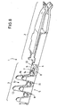
- An electrical contact element of a stamped sheet metal part has usually a contact region 2 and a crimping 3 on, over a transitional area 4 with each other in one piece Connection stand (Fig. 6).
- the spatial form of the contact area 4 can be arbitrary, which is why they are described in the description of the This invention is disregarded.
- the crimping area 3 has a crimping claw 5 which is suitable for crimping a flat ribbon flat conductor 27 is formed.
- the crimping claw 5 consists of a substantially elongated flat bottom plate 6 with the longitudinal edges 7 and 8, a free end edge 9 and a surface 10 and a Lower surface 11.
- the crimping claw of Fig. 6 has e.g. on the one longitudinal edge 7 two claw arms 12 and on the other longitudinal edge 8 three claw arms 12 in each case in a longitudinal row. In each row is each between two claw arms 12, a gap 13 is provided. A gap 13 opposite is on the other longitudinal edge each one claw arm 12 connected.
- the number of claw arms 12 and the gaps 13 can be selected; rich in the simplest case two diagonally opposite claw arms 12.
- the Claw arms 12 have a tongue shape and run in a rounded Tip region 16, which expediently wedge-shaped Thinner is marked with a beveled towards the free end flat outer surface. From the approximately triangular tongue shape of Claw arms 12 result in approximately V-shaped to U-shaped Lükken 13, so that the gaps 13 in about the negative shape of the claw arms 12 have.
- transverse grooves 15 are formed, the each a claw arm 12 in the transverse direction of the bottom plate. 6 are positioned opposite one another.
- the width of the grooves 15 corresponds approximately to the width of the tip portion 16 of a claw arm 12th
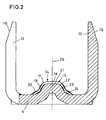
- Essential is the spatial shape of the bead 14 and the grooves 15 in Transverse direction of the bottom plate 6.
- a first embodiment of the invention goes the bead center 18 in the transverse direction over a convex cylindrical arc surface 17 in a convex, steeply sloping to the bottom plate 6 first inclined surface 19 above, to which a second convex, oblique, slightly flatter to the bottom plate 6 sloping, in the latter transition surface 20 connects.
- the angle of the surface 19 to the flat surface 10 of the bottom plate 6 is preferably between 50 and 70 °.
- the lies Angle between the surface 20 and the surface 10 of the bottom plate 6 preferably between 20 and 40 °.
- the groove bottom has a groove zenith 21 in the transverse direction over a convex cylindrical arc surface 22 in an oblique, convex, steeply sloping to the bottom plate 6 sloping surface 23, to which another convex, oblique, slightly flatter to the bottom plate 6 sloping, in the latter transition surface 24th followed.
- the angle of the surface 23 to the flat surface 10 of the bottom plate 6 is between 50 and 70 °. In addition, the angle is between the surface 24 and the surface 10 of the bottom plate 6 between 20 and 40 °.
- the grooves 15 extend transversely across the entire bead 14.
- the groove design according to the invention is necessary only on the side on which the groove 15 a Claw arm 12 is arranged opposite because of this claw arm only cooperates with this groove half.
- the invention provides that the respective claw arm 12 in such a way it is curled up that he with his outer surface against the bead 14 and the groove 15 on its longitudinal side adjacent to the longitudinal center 26 is pressed, with a flat ribbon flat conductor 27 between them is arranged.
- the rolling radius of the claw arm 12 is on the angle of the slope 19 and / or 23 to the bottom plate 6 such agreed that the unavoidable springback of the claw arm 12 after crimping and / or with a pulling action on the flat ribbon flat conductor causes a self-locking of the claw spring arm becomes.
- This self-locking illustrate the figures 7 and 8.
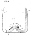
- FIG. 3 Another embodiment of the crimping claw according to the invention (Fig. 3, 4) provides that the zenith 18 of the bead 14 with the Zenith 21 of the grooves 15 coincides. Out of this spatial form results a longer outlet slope 24 of the grooves 15 in comparison to the outlet slope 20 of the bead 14. This embodiment represents a manufacturing simplification.
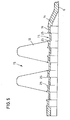
- the embodiment of the invention according to Fig. 5 provides that the on both sides outer edges of the grooves 15 formed like a blade are and survive beyond the bead surface, from which cutting 25 result. This will be an additional contact allows the conductor 30 from the bottom.
- the cutting 25 penetrate the base material 29 and contact the Head 30 of the flat ribbon flat conductor 27th
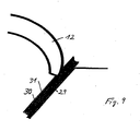
- Fig. 9 provides that the Flachbandflachleiter 27 no Kupferiva Chemistry 28 has. Of the Tip area 16 of the claw arm 12 penetrates the cover layer 31 of the flat ribbon flat conductor 27 and scrapes this and contacted with its outer surface on the ladder 30.
- the invention thus provides a self-locking of the claw arms in the contacting area after crimping and defined contact zones.
- a gas-tight contact zone whereby Flachbandflachleiter be contacted of any kind can. It can be a safe contact in long-term operation be guaranteed.
- the contact is made with the outlet bend the crimp claw, which is supported on a bevel, the is formed by the flat conductor which lies on the sloping surface of the Bead and the groove rests.
- the contacting takes place via the inclined surface 19/23 of the bead and / or the groove, in particular the contact also on the outlet slope of the Both elements can be done.
- the inclined surfaces 19, 23 and / or 20, 24 slightly convex in Direction to the flat ribbon ladder arched.
Landscapes
- Connections Effected By Soldering, Adhesion, Or Permanent Deformation (AREA)
- Connection Of Batteries Or Terminals (AREA)
- Switch Cases, Indication, And Locking (AREA)
- Connector Housings Or Holding Contact Members (AREA)
- Manufacturing Of Electrical Connectors (AREA)
- Coupling Device And Connection With Printed Circuit (AREA)
- Contacts (AREA)
- Manufacture Of Switches (AREA)
- Conductive Materials (AREA)
Abstract
Description
- Fig. 1
- perspektivisch eine Draufsicht auf eine erste Ausführungsform einer erfindungsgemäßen Crimpkralle, bei der die Krallenarme der einen Seite nicht eingezeichnet sind;
- Fig. 2
- einen Querschnitt durch die Crimpkralle nach Fig. 1 im Querrillenbereich;
- Fig. 3
- perspektivisch eine Draufsicht auf eine weitere Ausführungsform einer erfindungsgemäßen Crimpkralle, bei der die Krallenarme der einen Seite ebenfalls nicht eingezeichnet sind;
- Fig. 4
- einen Querschnitt durch die Crimpkralle nach Fig. 3 im Querrillenbereich;
- Fig. 5
- einen Längsschnitt durch eine dritte Ausführungsform einer erfindungsgemäßen Crimpkralle;
- Fig. 6
- eine perspektivische Draufsicht auf ein elektrisches Kontaktelement mit einer erfindungsgemäßen Crimpkralle.
- Fig. 7
- einen Querschnitt durch eine eingerollte Crimpkralle mit Flachbandflachleiter, Kontaktierung auf Kupferfreifläche gegenüber einer ersten Schrägen in der Crimpkralle;
- Fig. 8
- einen Querschnitt durch eine eingerollte Crimpkralle mit Flachbandflachleiter, Kontaktierung auf Kupferfreifläche gegenüber einer zweiten Schrägfläche in der Crimpkralle;
- Fig. 9
- schematisch eine Crimpkralle für Flachbandflachleiter ohne Kupferfreifläche;
- Fig. 10
- perspektivisch eine erfindungsgemäße Crimpkralle mit einem anderen Kontaktbereich 2.
Claims (22)
- Crimpkralle eines elektrischen Kontaktelements aus einem Blechstanzteil mit einer langgestreckten Bodenplatte (6), an deren Längskanten (7, 8) mindestens jeweils ein Krallenarm (12) angebunden ist und die Krallenarme (12) sich diagonal gegenüberliegend angeordnet sind, wobei die Bodenplatte (6) zwischen den Krallenarmen (12) einen sich in Längsrichtung der Bodenplatte (6) erstreckenden Wulst (14) mit Querrillen (15) aufweist und die Querrillen (15) jeweils einem Krallenarm (12) gegenüberliegend angeordnet sind,
dadurch gekennzeichnet , daß die Rillen (15) in Richtung des jeweiligen Krallenarms (12) von einem Zenitbereich (21) ausgehend eine konvexe Zylinderbogenfläche (22) und im Anschluß daran eine konvexe, schräg und steil zur Oberfläche (10) der Bodenplatte (6) abfallende Fläche (23) aufweisen, wobei die Fläche (23) derart ausgebildet und angeordnet ist, daß sie eine Selbsthemmung des eingerollten Krallenarms (12) gegen ein Öffnen des eingerollten Krallenarmbogens erzeugt. - Crimpkralle nach Anspruch 1,
dadurch gekennzeichnet, daß der Winkel der Fläche (23) zur ebenen Oberfläche (10) der Bodenplatte (6) zwischen 50 und 70° liegt. - Crimpkralle nach Anspruch 1 und/oder 2,
dadurch gekennzeichnet , daß sich an die Fläche (23) eine weitere konvexe, schräge, etwas flachere, zur Bodenplatte (6) abfallende Fläche (24) anschließt, die vorzugsweise derart ausgebildet und angeordnet ist, daß sie ebenfalls eine Selbsthemmung des eingerollten Federarms (12) erzeugt. - Crimpkralle nach Anspruch 3,
dadurch gekennzeichnet , daß die Fläche (24) in die ebene Oberfläche (10) der Bodenplatte (6) übergeht. - Crimpkralle nach Anspruch 3 und/oder 4,
dadurch gekennzeichnet , daß der Winkel zwischen der Fläche (24) und der Oberfläche (10) der Bodenplatte (6) zwischen 20 und 40° liegt. - Crimpkralle nach einem oder mehreren der Ansprüche 1 bis 5,
dadurch gekennzeichnet , daß der Wulst (14) in Richtung jeweils eines Krallenarms (12) von einem Zenitbereich (18) ausgehend eine konvexe Zylinderbogenfläche (17) und im Anschluß daran eine konvexe, schräg und steil zur Oberfläche (10) der Bodenplatte (6) abfallende Fläche (19) aufweist, wobei die Fläche (19) vorzugsweise ebenfalls derart ausgebildet und angeordnet ist, daß sie eine Selbsthemmung des eingerollten Krallenarms (12) gegen Öffnen des eingerollten Krallenarmbogens erzeugt. - Crimpkralle nach Anspruch 6,
dadurch gekennzeichnet , daß der Winkel der Fläche (19) zur ebenen Oberfläche (10) der Bodenplatte (6) zwischen 50 und 70° liegt. - Crimpkralle nach Anspruch 6 und/oder 7,
dadurch gekennzeichnet , daß sich an die Fläche (19) eine weitere konvexe, schräge, etwas flachere, zur Bodenplatte (6) abfallende Fläche (20) anschließt, die vorzugsweise derart ausgebildet und angeordnet ist, daß sie ebenfalls eine Selbsthemmung des eingerollten Federarms (12) erzeugt. - Crimpkralle nach Anspruch 8,
dadurch gekennzeichnet , daß die Fläche (20) in die ebene Oberfläche (10) der Bodenplatte (6) übergeht. - Crimpkralle nach Anspruch 8 und/oder 9,
dadurch gekennzeichnet , daß der Winkel zwischen der Fläche (20) und der Oberfläche (10) der Bodenplatte (6) zwischen 20 und 40° liegt. - Crimpkralle nach einem oder mehreren der Ansprüche 6 bis 10,
dadurch gekennzeichnet , daß die Schrägen der Flächen (23 und 19) den gleichen Winkel aufweisen. - Crimpkralle nach einem oder mehreren der Ansprüche 6 bis 11,
dadurch gekennzeichnet , daß die Schrägen der Flächen (24 und 20) den gleichen Winkel aufweisen. - Crimpkralle nach einem oder mehreren der Ansprüche 1 bis 12,
dadurch gekennzeichnet , daß der Zenitbereich (18) des Wulstes (14) mit dem Zenitbereich (21) der Rillen (15) fluchtet. - Crimpkralle nach einem oder mehreren der Ansprüche 1 bis 13,
dadurch gekennzeichnet , daß an den Längskanten (7, 8) mehrere Krallenarme (12) jeweils in Reihe angeordnet sind, wobei zwischen den Krallenarmen (12) einer Reihe jeweils eine Lücke (13) vorgesehen ist. - Crimpkralle nach Anspruch 14,
dadurch gekennzeichnet , daß einer Lücke (13) gegenüberliegend an der anderen Längskante jeweils ein Krallenarm (12) angebunden ist. - Crimpkralle nach einem oder mehreren der Ansprüche 1 bis 15,
dadurch gekennzeichnet , daß die Krallenarme (12) eine Zungenform aufweisen und in einem abgerundeten Spitzenbereich (16) auslaufen. - Crimpkralle nach Anspruch 16,
dadurch gekennzeichnet , daß die Krallenarme (12) im Spitzenbereich (16) keilförmig dünner geprägt sind mit einer zum freien Ende hin abgeschrägten ebenen Außenfläche. - Crimpkralle nach Anspruch 16 und/oder 17,
dadurch gekennzeichnet , daß aus der etwa dreieckförmigen Zungenform der Krallenarme (12) etwa V-förmige bis U-förmige Lücken (13) resultieren, so daß die Lücken (13) in etwa die Negativform der Krallenarme (12) aufweisen. - Crimpkralle nach einem oder mehreren der Ansprüche 1 bis 18,
dadurch gekennzeichnet , daß die Breite der Rillen (15) etwa der Breite des Spitzenbereichs (16) der Krallenarme (12) entspricht. - Crimpkralle nach einem oder mehreren der Ansprüche 1 bis 19,
dadurch gekennzeichnet , daß sich die Rillen (15) quer über den gesamten Wulst (14) erstrecken. - Crimpkralle nach einem oder mehreren der Ansprüche 1 bis 20,
dadurch gekennzeichnet , daß die beidseitigen Außenkanten der Rillen (15) schneidenförmig ausgebildet sind und über die Wulstoberfläche überstehen, woraus Schneidkanten (25) resultieren. - Crimpkralle nach einem oder mehreren der Ansprüche 1 bis 21,
dadurch gekennzeichnet , daß die Flächen (19, 23 und/oder 20, 24) konvex in Richtung auf den Flachbandflachleiter gewölbt sind.
Applications Claiming Priority (3)
| Application Number | Priority Date | Filing Date | Title |
|---|---|---|---|
| DE20106497U | 2001-04-12 | ||
| DE20106497U DE20106497U1 (de) | 2001-04-12 | 2001-04-12 | Crimpkralle eines elektrischen Kontaktelements |
| EP02740248A EP1378024B1 (de) | 2001-04-12 | 2002-04-11 | Crimpkralle eines elektrischen kontaktelements |
Related Parent Applications (1)
| Application Number | Title | Priority Date | Filing Date |
|---|---|---|---|
| EP02740248A Division EP1378024B1 (de) | 2001-04-12 | 2002-04-11 | Crimpkralle eines elektrischen kontaktelements |
Publications (2)
| Publication Number | Publication Date |
|---|---|
| EP1603194A2 true EP1603194A2 (de) | 2005-12-07 |
| EP1603194A3 EP1603194A3 (de) | 2006-02-22 |
Family
ID=7955731
Family Applications (2)
| Application Number | Title | Priority Date | Filing Date |
|---|---|---|---|
| EP05018806A Withdrawn EP1603194A3 (de) | 2001-04-12 | 2002-04-11 | Crimpkralle eines elektrischen Kontaktelements |
| EP02740248A Expired - Lifetime EP1378024B1 (de) | 2001-04-12 | 2002-04-11 | Crimpkralle eines elektrischen kontaktelements |
Family Applications After (1)
| Application Number | Title | Priority Date | Filing Date |
|---|---|---|---|
| EP02740248A Expired - Lifetime EP1378024B1 (de) | 2001-04-12 | 2002-04-11 | Crimpkralle eines elektrischen kontaktelements |
Country Status (4)
| Country | Link |
|---|---|
| EP (2) | EP1603194A3 (de) |
| AT (1) | ATE319199T1 (de) |
| DE (3) | DE20106497U1 (de) |
| WO (1) | WO2002084805A1 (de) |
Cited By (1)
| Publication number | Priority date | Publication date | Assignee | Title |
|---|---|---|---|---|
| EP1811602A1 (de) * | 2006-01-24 | 2007-07-25 | Hirschmann Car Communication GmbH | Aufdopplung im Crimpbereich eines Steckers oder eines Kupplers |
Families Citing this family (2)
| Publication number | Priority date | Publication date | Assignee | Title |
|---|---|---|---|---|
| DE20207230U1 (de) * | 2002-05-07 | 2003-09-18 | Grote & Hartmann Gmbh & Co Kg, 42369 Wuppertal | Crimpkralle eines elektrischen Kontaktelements |
| CN212161961U (zh) * | 2020-05-26 | 2020-12-15 | 宁德时代新能源科技股份有限公司 | 信号传输端子、采样装置、电池模组以及装置 |
Family Cites Families (4)
| Publication number | Priority date | Publication date | Assignee | Title |
|---|---|---|---|---|
| GB1474249A (en) | 1974-01-09 | 1977-05-18 | Amp Inc | Electrical contact for flat conductor cable |
| GB1466086A (en) * | 1974-07-18 | 1977-03-02 | Cannon Electric Great Britain | Electrical terminations |
| JPH0747810Y2 (ja) | 1990-05-09 | 1995-11-01 | 住友電装株式会社 | 可撓性平型導体ケーブル用電気接続子 |
| JP3149365B2 (ja) | 1996-09-10 | 2001-03-26 | タイコエレクトロニクスアンプ株式会社 | 電気コンタクト |
-
2001
- 2001-04-12 DE DE20106497U patent/DE20106497U1/de not_active Expired - Lifetime
-
2002
- 2002-04-11 EP EP05018806A patent/EP1603194A3/de not_active Withdrawn
- 2002-04-11 WO PCT/DE2002/001361 patent/WO2002084805A1/de not_active Ceased
- 2002-04-11 AT AT02740248T patent/ATE319199T1/de not_active IP Right Cessation
- 2002-04-11 DE DE10291670T patent/DE10291670D2/de not_active Expired - Fee Related
- 2002-04-11 DE DE50205949T patent/DE50205949D1/de not_active Expired - Lifetime
- 2002-04-11 EP EP02740248A patent/EP1378024B1/de not_active Expired - Lifetime
Cited By (1)
| Publication number | Priority date | Publication date | Assignee | Title |
|---|---|---|---|---|
| EP1811602A1 (de) * | 2006-01-24 | 2007-07-25 | Hirschmann Car Communication GmbH | Aufdopplung im Crimpbereich eines Steckers oder eines Kupplers |
Also Published As
| Publication number | Publication date |
|---|---|
| ATE319199T1 (de) | 2006-03-15 |
| DE50205949D1 (de) | 2006-04-27 |
| EP1378024A1 (de) | 2004-01-07 |
| WO2002084805A1 (de) | 2002-10-24 |
| DE10291670D2 (de) | 2004-04-15 |
| EP1378024B1 (de) | 2006-03-01 |
| EP1603194A3 (de) | 2006-02-22 |
| DE20106497U1 (de) | 2001-07-19 |
Similar Documents
| Publication | Publication Date | Title |
|---|---|---|
| DE4223540C2 (de) | Querverbinder für Reihenklemmen | |
| DE2816039C2 (de) | Elektrische Anschlußklemme | |
| DE1765818C3 (de) | Verbindungsklemme zum Andrücken an elektrische Drähte | |
| EP0459144A1 (de) | Schneid-Klemm-Kontakt | |
| CH647895A5 (de) | Elektrischer anschlussteil, verfahren zu dessen verbinden mit einem elektrischen leiter sowie verbinder mit einer mehrzahl von anschlussteilen. | |
| DE102010039655A1 (de) | Elektrische Verbindungsklemme sowie Verfahren und Vorrichtung zum Herstellen einer elektrischen Verbindungsklemme | |
| DE3203751A1 (de) | Drahtinstallationswerkzeug und verfahren zum installieren eines drahtes in einem elektrischen verbinder | |
| CH650108A5 (de) | Kontaktorgan. | |
| WO2004084353A1 (de) | Elektrisches kontaktelement für einen flachleiter | |
| DE68910246T2 (de) | Abgeschirmtes Verbindungsgehäuse. | |
| EP3866265A1 (de) | Federkraftklemmanschluss | |
| DE2055583B2 (de) | Verbindungsklemme zum Andrücken an elektrische Drähte | |
| DE10209708B4 (de) | Elektrisches Kontaktelement | |
| EP1378024B1 (de) | Crimpkralle eines elektrischen kontaktelements | |
| DE9308142U1 (de) | Flachfederkontakt für eine Steckverbindung | |
| DE3937089C2 (de) | Elektrischer Anschluß für Folienleiter | |
| EP0952765B1 (de) | Kontaktstreifen zum elektrischen Kontaktieren und/oder zur Erzielung einer gegen hochfrequente elektromagnetische Wellen dichten Verbindung sowie zugehörige Abschirmanordnung | |
| DE2815890A1 (de) | Elektrischer verbinderkontakt fuer den anschluss eines isolierten leiters | |
| DE4301949C2 (de) | Steckkontaktbuchse für einen Flachsteckstift | |
| DE19523557A1 (de) | Crimpkrallen aus hartem Material | |
| EP0901186A2 (de) | Anschlusselement für Schirmkabel | |
| DE3002321A1 (de) | Befestigungselement | |
| DE20207232U1 (de) | Folienleiterverbindung und Kontaktelement hierfür | |
| DE10320536B4 (de) | Crimpkralle eines elektrischen Kontaktelements | |
| DE4323286C2 (de) | Schneidklemm-Kontaktelement und Verfahren zur Herstellung eines Schneidklemm-Kontaktelements |
Legal Events
| Date | Code | Title | Description |
|---|---|---|---|
| PUAI | Public reference made under article 153(3) epc to a published international application that has entered the european phase |
Free format text: ORIGINAL CODE: 0009012 |
|
| 17P | Request for examination filed |
Effective date: 20050830 |
|
| AC | Divisional application: reference to earlier application |
Ref document number: 1378024 Country of ref document: EP Kind code of ref document: P |
|
| AK | Designated contracting states |
Kind code of ref document: A2 Designated state(s): AT BE CH CY DE DK ES FI FR GB GR IE IT LI LU MC NL PT SE TR |
|
| PUAL | Search report despatched |
Free format text: ORIGINAL CODE: 0009013 |
|
| RIN1 | Information on inventor provided before grant (corrected) |
Inventor name: DEHNERT, OLAF Inventor name: DEUTMARG, STEFAN Inventor name: SCHLEIFE, BERND |
|
| AK | Designated contracting states |
Kind code of ref document: A3 Designated state(s): AT BE CH CY DE DK ES FI FR GB GR IE IT LI LU MC NL PT SE TR |
|
| RIC1 | Information provided on ipc code assigned before grant |
Ipc: H01R 4/24 20060101AFI20060105BHEP Ipc: H01R 4/20 20060101ALI20060105BHEP |
|
| STAA | Information on the status of an ep patent application or granted ep patent |
Free format text: STATUS: THE APPLICATION HAS BEEN WITHDRAWN |
|
| 18W | Application withdrawn |
Effective date: 20060622 |