EP1603265A2 - Dispositif et procédé pour la détection d'une trame de multiplexage par division temporelle dans un système de communication mobile - Google Patents
Dispositif et procédé pour la détection d'une trame de multiplexage par division temporelle dans un système de communication mobile Download PDFInfo
- Publication number
- EP1603265A2 EP1603265A2 EP05011918A EP05011918A EP1603265A2 EP 1603265 A2 EP1603265 A2 EP 1603265A2 EP 05011918 A EP05011918 A EP 05011918A EP 05011918 A EP05011918 A EP 05011918A EP 1603265 A2 EP1603265 A2 EP 1603265A2
- Authority
- EP
- European Patent Office
- Prior art keywords
- frame
- metric
- path metric
- bit
- value
- Prior art date
- Legal status (The legal status is an assumption and is not a legal conclusion. Google has not performed a legal analysis and makes no representation as to the accuracy of the status listed.)
- Withdrawn
Links
Images


Classifications
-
- H—ELECTRICITY
- H04—ELECTRIC COMMUNICATION TECHNIQUE
- H04L—TRANSMISSION OF DIGITAL INFORMATION, e.g. TELEGRAPHIC COMMUNICATION
- H04L1/00—Arrangements for detecting or preventing errors in the information received
- H04L1/004—Arrangements for detecting or preventing errors in the information received by using forward error control
- H04L1/0045—Arrangements at the receiver end
- H04L1/0054—Maximum-likelihood or sequential decoding, e.g. Viterbi, Fano, ZJ algorithms
-
- H—ELECTRICITY
- H04—ELECTRIC COMMUNICATION TECHNIQUE
- H04L—TRANSMISSION OF DIGITAL INFORMATION, e.g. TELEGRAPHIC COMMUNICATION
- H04L1/00—Arrangements for detecting or preventing errors in the information received
- H04L1/004—Arrangements for detecting or preventing errors in the information received by using forward error control
- H04L1/0056—Systems characterized by the type of code used
- H04L1/0067—Rate matching
- H04L1/0068—Rate matching by puncturing
-
- H—ELECTRICITY
- H04—ELECTRIC COMMUNICATION TECHNIQUE
- H04L—TRANSMISSION OF DIGITAL INFORMATION, e.g. TELEGRAPHIC COMMUNICATION
- H04L1/00—Arrangements for detecting or preventing errors in the information received
- H04L1/004—Arrangements for detecting or preventing errors in the information received by using forward error control
- H04L1/0072—Error control for data other than payload data, e.g. control data
-
- H—ELECTRICITY
- H04—ELECTRIC COMMUNICATION TECHNIQUE
- H04L—TRANSMISSION OF DIGITAL INFORMATION, e.g. TELEGRAPHIC COMMUNICATION
- H04L1/00—Arrangements for detecting or preventing errors in the information received
- H04L1/20—Arrangements for detecting or preventing errors in the information received using signal quality detector
- H04L1/201—Frame classification, e.g. bad, good or erased
-
- H—ELECTRICITY
- H04—ELECTRIC COMMUNICATION TECHNIQUE
- H04L—TRANSMISSION OF DIGITAL INFORMATION, e.g. TELEGRAPHIC COMMUNICATION
- H04L1/00—Arrangements for detecting or preventing errors in the information received
- H04L1/004—Arrangements for detecting or preventing errors in the information received by using forward error control
- H04L1/0056—Systems characterized by the type of code used
- H04L1/0061—Error detection codes
Definitions
- the present invention relates to an apparatus and a method for receiving control channels in a mobile communication system providing packet data services. More particularly, the present invention relates to an apparatus and a method for improving reception reliability for control channels by detecting time division multiple (TDM) frames transmitted through the control channels in a TDM mobile communication system.
- TDM time division multiple
- TDM time division multiple
- CDMA 2000 1 ⁇ Rev. D standardization which has been suggested by the 3GPP2 group, the broadcast service is called a "broadcast multicast service".
- the CDMA 2000 1x Rev. D standardization defines the size of physical channels used in a 1 ⁇ EV-DV (Evolution for Data & Voice) system capable of simultaneously providing packet services and voice services.
- F-DCCH forward dedicated channel
- BCMCS Broadcast and Multicast Service
- broadcast data or push to talk (PTT) service data are transmitted to a plurality of users through one physical channel.
- the control information is transmitted to the users through the F-DCCH in a forward link of the 1 ⁇ EV-DV system providing the BCMCS service.
- the users may share the same physical channel through the TDM scheme and the users are differentiated from each other by means of a long code mask.
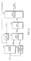
- FIG. 1 is a block diagram illustrating the structure of a transmitter 100 and a receiver 200 in a conventional mobile communication system.
- the standardization for a baseband physical channel of a F-DCCH used as a control channel in the 1 ⁇ EV-DV system and the structure of the receiver 200 will be described with reference to FIG. 1.
- a cyclic redundancy checking (CRC) inserter 110 inserts CRC bits into information bits in order to check for errors in the information bits transmitted to specific users as control information and sends the information bits with the CRC bits to a channel coder 120.
- the channel coder 120 codes the information bits having the CRC bits through a predetermined channel coding scheme and sends the channel-coded information bits to a scrambler 130.
- the channel coding scheme may include a convolutional coding scheme.
- the scrambler 130 performs long code mask scrambling with respect to channel-coded information bits to provide security to the channel-coded information bits per each user. Then, the scrambler 130 sends the channel-coded information bits to a spreader 140. Upon receiving the channel-coded information bits, the spreader 140 spreads the channel-coded information bits by using PN codes and Walsh codes and sends them to a radio network. Thus, the spread information bits in the form of frame units are transmitted to the receiver 200 through the F-DCCH.
- a despreader 210 of the receiver 200 despreads the information bits of the frames by using the PN codes and Walsh codes and sends them to a descrambler 220.
- the descrambler 220 descrambles the despread information bits by using the long code mask and send them to a channel decoder 230.
- the channel decoder 230 decodes the descrambled information bits and sends the decoded information bits to a CRC inspector 240. If a convolution coder is used as the channel coder 120, a Viterbi decoder is used as the channel decoder 230.
- the CRC inspector 240 checks for a transmission error in the frame by using the CRC bits contained in the decoded bits and outputs error detection bits for determining the validity of the frame, that is, decoded bits.
- the users may share the same F-DCCH channel, through which information bits in the form of frame units are transmitted as control information for supporting the broadcast service, by means of the TDM scheme.
- the users may be differentiated from each other by using the long code mask.
- FIG. 2 is a schematic diagram illustrating the structure of a control channel through which control information is transmitted using the TDM scheme in the conventional mobile communication system.
- the control channel shown in FIG. 2 is the F-DCCH and control information transmitted to users (user 1, user 2, user3, etc) is time-multiplexed in a frame unit (T F ).
- the control information that is, the information bits are coded by using the long code mask allocated to each user, thereby differentiating the control information transmitted to each user.
- the receiver 200 shown in FIG. 1 descrambles the coded information bits by using the long code allocated to each mobile station. At this time, if the descrambled information bits belong to the TDM frame allocated to the receiver 200, the CRC inspector 240 of the receiver 200 outputs an error detection bit "Good” based on the characteristic of a code word. However, if the descrambled information bits belong to the TDM frame allocated to the other receiver, the CRC inspector 240 of the receiver 200 outputs an error detection bit "Bad” due to the discord of the long code. In addition, the CRC inspector 240 of the receiver 200 outputs the error detection bit "Bad” when the reception quality of the frame is lowered so that the receiver 200 may detect whether the reception frame is adaptable for the receiver 200.
- each user can check whether the frame received through the control channel, that is, the F-DCCH is adaptable for the user by using the long code and the CRC.
- the control channel that is, the F-DCCH is adaptable for the user by using the long code and the CRC.
- the users of the frame are differentiated from each other through the above manner, it is difficult to ensure the reception reliability of the control channel.
- the frames transmitted to other users may not match with the code word because scrambling and descrambling processes for the frames are performed based on mutually different long codes after the frames have been descrambled in the receiver 200, so that the frames represent abnormal characteristics as if they have no control signals.
- a false alarm probability (FAR) of the CRC is about 2.44 ⁇ 10 -4 , which means that the detection error periodically occurs in every 82 seconds.
- the FAR of the CRC is very high.
- the F-DCCH since the F-DCCH transmits an L3 signaling signal (that is, the control information), it is necessary to ensure superior reception reliability with respect to the transmission signal of the F-DCCH in order to stably provide the users with broadcast services.
- an object of the present invention is to provide an apparatus and a method for improving reception reliability for control channels by easily detecting time division multiple (TDM) frames, which are allocated to each user and transmitted through the control channels of a TDM mobile communication system where the users share the control channels.
- TDM time division multiple
- a method for detecting a time division multiplexing (TDM) frame transmitted through a forward control channel comprising the steps of: receiving the frame through the forward control channel and performing a cyclic redundancy checking (CRC) with respect to the frame, thereby outputting a first error detection bit; measuring reception power for the frame; calculating a first path metric when decoding a channel of the frame, estimating a second path metric by using the first path metric and the reception power, and outputting a second error detection bit by comparing the second path metric with a predetermined threshold value; and creating and outputting a frame quality bit for detecting a validity of the frame based on the first and second error detection bits.
- CRC cyclic redundancy checking
- an apparatus for detecting a time division multiplexing (TDM) frame transmitted through a forward control channel comprising a channel decoder for receiving the frame in order to decode a channel of the frame and to calculate and output a first path metric when decoding the channel of the frame; a cyclic redundancy checking (CRC) inspector for outputting a first error detection bit by performing a CRC inspection with respect to decoded bits output from the channel decoder; a reception power measurement unit for measuring reception power for the frame; and a frame quality bit generating unit for estimating a second path metric by using the first path metric and the reception power, outputting a second error detection bit by comparing the second path metric with a predetermined threshold value, and creating and outputting a frame quality bit for detecting a validity of the frame based on the first and second error detection bits.
- CRC cyclic redundancy checking
- a method for detecting a time division multiplexing (TDM) frame transmitted through a forward control channel comprising the steps of depuncturing control channel information by using an allocated long code mask value, thereby separately outputting data and a power control bit; performing channel-decoding and cyclic redundancy checking (CRC) inspection with respect to the data, thereby outputting decoded data; calculating a metric by using the data and power control bit; and comparing the calculated metric with a predetermined threshold value and generating frame quality bits based on results of comparison and the CRC inspection.
- TDM time division multiplexing
- an apparatus for detecting a time division multiplexing (TDM) frame transmitted through a forward control channel comprising a depuncturing unit for depuncturing control channel information by using a long code mask value allocated thereto in order to separately output data and a power control bit; a channel decoder for performing channel-decoding and cyclic redundancy checking (CRC) inspection with respect to the data in order to output decoded data; a metric calculator for calculating a metric by using the data and power control bit; a comparator for comparing an output of the metric calculator with a predetermined threshold value and outputting a result thereof; and a frame quality bit generator for generating frame quality bits based on an output of the comparator and a result of the CRC inspection.
- a depuncturing unit for depuncturing control channel information by using a long code mask value allocated thereto in order to separately output data and a power control bit
- CRC channel-decoding and cyclic redundancy checking
- a second path metric is estimated by taking a first path metric and reception power for the TDM frame into consideration.
- the second path metric is compared with a predetermined threshold value of the path metric in order to determine a validity of a reception frame.
- a first error detection bit is obtained based on the CRC result of a channel-decoded reception frame and a second error detection bit is obtained based on the validity of the reception frame, which is determined by using the second path metric. If both first and second error detection bits are available, it is determined that the frame is normally received through the control channel.
- FIG. 3A is a graph illustrating the method for determining the reception error of the frame based on reception power for a TDM frame in a mobile communication system.
- a dotted line shown in FIG. 3A represents first and second frames 310 and 320 which have control information to be transmitted to users, and a solid line shown in FIG. 3A represents a third frame 330 which has no control information.
- the first frame 310 is a desired frame having control information to be transmitted to a specific user
- the second frame 320 is an undesired frame having control information to be transmitted to other users
- the third frame 330 is an empty frame.
- FIG. 3A shows a probability density function (PDF) according to the reception power for the first to third frames 310 to 330.
- PDF probability density function
- FIG. 3B is a graph illustrating a method for determining the reception error of the frame based on the path metric of the TDM frame in a mobile communication system.
- FIG. 3B shows the PDF according to the path metric of the first to third frames 310 to 330.
- the path metric may be obtained by using a maximum correlation value selected from among correlations values between the received bit array and the postulated code word, or by using a minimum Euclidean distance or a minimum squared Euclidean distance between the received bit array and the postulated code word. In FIG. 3B, the maximum correlation value is used for the path metric.
- the path metric can be obtained based on an output of a Viterbi decoder, which is used as a channel decoder of the receiver 200. That is, according to the PDF of the path metric obtained from the output of the Viterbi decoder, if the second frame 320 for other users is received in the receiver 200, the frame signals are descrambled in the receiver 200 based on the mutually different long codes, so that the input signal of the Viterbi decoder does not match with the code word. Therefore, the second frame 320 represents characteristics similar to those of the third frame 330, which does not have the control information, so that it is possible to distinguish the second frame 320 from the first frame 310.
- the reception power of the receivers per each frame may significantly vary. Accordingly, the path metric of the second frame 320 transmitted to other users also varies, so that it is difficult to distinguish the frames 310 to 330 if the path metric of the frames is only used as shown in FIG. 3B.
- the frame error detection method using the reception power for the frames or the path metric of the frames does not provide a stable result, so that problems may occur if the above methods are applied to a frame reliability test after the CRC test has been performed.
- the reception power for the frames and the path metric of the frames are simultaneously used for detecting the reception error of the frame.
- a characteristic equation is suggested in order to estimate the second path metric by taking the first path metric and the reception power for the frame into consideration based on a proportion between the first path metric and the reception power.
- the second path metric obtained through the characteristic equation is compared with the predetermined threshold value of the path metric, thereby determining the validity of the reception frame.
- the frame error detection is carried out together with the CRC inspection, thereby improving reliability for the frame error detection.
- FIG. 5 is a block diagram illustrating an internal structure of a TDM frame detection unit of a receiver in a mobile communication system according to the first embodiment of the present invention.
- the receiver shown in FIG. 5 employs a forward dedicated control channel (F-DCCH) as a control channel in such a manner that users can share the control channel using the TDM scheme and determines the validity of the frame received therein through the control channel based on the frame error detection scheme according to an embodiment of the present invention.
- F-DCCH forward dedicated control channel
- the channel decoder 510 has a predetermined code word set for estimating the first path metric. In addition, the channel decoder 510 estimates the maximum correlation value between the bit array of the reception frame and the code word set in order to output the first path metric (PM[k]). Also, the channel decoder 510 estimates the minimum Euclidean distance or the minimum squared Euclidean distance between the bit array of the reception frame and the code word set in order to output the first path metric (PM[k]). The channel decoder 510 outputs the code word as decoded bits if the maximum correlation value for the code word has been found.
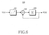
- a reception power measurement unit 530 shown in FIG. 5 measures reception power (PE[k]) for the corresponding frame from the input signal (Y[n]) and sends the reception power to a path metric estimator 540.
- reception power measurement unit 530 measures reception power (PE[k]) for the corresponding frame from the input signal (Y[n]) and sends the reception power to a path metric estimator 540.
- FIG. 6 is a block diagram illustrating an internal structure of the reception power measurement unit 530 shown in FIG. 5.
- the reception power measurement unit 530 performs a m th -power operation 531 with respect to an absolute value (
- n is a symbol index and k is a frame index.
- the degree of m is basically "1".
- the first path metric (PM[k]) output from the channel decoder 510 can be expressed as a linear combination of the input signal Y[n].
- the path metric estimator 540 shown in FIG. 5 estimates the second path metric (FQM [k]) for determining the validity of the reception frame by using the proportion between the first path metric (PM[k]) calculated from the channel decoder 510 and the reception power (PE[k]) calculated from the reception power measurement unit.
- the second path metric (FQM [k]) can be estimated through two schemes, which will be described below, depending on algorithms used for calculating the path metric.
- the first embodiment of the present invention suggests two characteristic equations for defining the above proportional relationship, which will be described later in detail.
- the algorithm for estimating the path metric may use the maximum correlation value between the bit array and the code word of the reception frame, and the minimum Euclidean distance or the minimum squared Euclidean distance between the bit array and the code word of the reception frame.
- FQM [k] a basic principle of estimating the second path metric
- the path metric is proportional to the reception power for the frame.
- the frame allocated to the receiver may have a relatively large path metric in comparison with the reception power for the frame, and the frame allocated to the other receiver may have a relatively small path metric in comparison with the reception power for the frame.
- the second path metric (FQM[k]) can be estimated based on the proportion between the path metrics of the frames.
- the path metric is inversely proportional to the reception power for the frame.
- the frame allocated to the receiver may have a relatively small path metric in comparison with the reception power for the frame, and the frame allocated to the other receiver may have a relatively large path metric in comparison with the reception power for the frame.
- the second path metric (FQM[k]) can be estimated based on the proportion between the path metrics of the frames.
- a differential value between the first path metric (PM[k]) and the reception power (PE[k]) multiplied by a weight ( ⁇ ) is estimated as the second path metric (FQM[k]). That is, the frame allocated to the receiver can be distinguished from the frames allocated to other users based on the weight ( ⁇ ). According to the test result performed by a user in accordance with an embodiment of the present invention, the frames can be efficiently distinguished from each other when the weight (a) has a value of about 0.06. However, the value of the weight (a) can be properly changed by taking the type of mobile communication systems or variation of communication environment into consideration.
- the second path metric (FQM[k]) obtained through Equation 1 does not sensitively depend on the fading channel or the location of the receiver as compared with that obtained through Equation 2.
- the second path metric (FQM[k]) obtained through Equation 2 represents the superior frame distinguishment performance as compared with that of the first second path metric (FQM[k]) obtained through Equation 1.
- the second path metric (FQM[k]) estimated through the above manner is transmitted to a comparator 550.
- the comparator 550 compares the second path metric (FQM[k]) with a predetermined threshold value of the path metric and outputs a second error detection bit (e2) for determining the validity of the reception frame.
- the comparator 550 If the first path metric has been estimated by using the maximum correlation value, the comparator 550 outputs the second error detection bit (e2) indicating that the reception frame is a valid frame when the second path metric is larger than the threshold value of the path metric. In contrast, when the second path metric is smaller than the threshold value of the path metric, the comparator 550 outputs the second error detection bit (e2) indicating that the reception frame has an error.
- the weigh ( ⁇ ) shown in Equation 4 can be obtained through various tests.
- the comparator 550 outputs the second error detection bit (e2) indicating that the reception frame is a valid frame when the second path metric is smaller than the threshold value of the path metric.
- the comparator 550 outputs the second error detection bit (e2) indicating that the reception frame has an error.
- Equations 3 and 4 can be replaced with Equations 5 and 6.
- the comparator 550 outputs the second error detection bit (e2) indicating that the reception frame is a valid frame when the second path metric is larger than the threshold value of the path metric.
- the weigh ( ⁇ ) shown in Equation 6 can be obtained through various tests.
- a frame quality bit generator 560 shown in FIG. 5 receives the first error detection bit (e1) output from the CRC inspector 520 and the second error detection bit (e2) output from the comparator 550 and outputs a predetermined frame quality bit used for finally determining the validity of the reception frame.
- the frame quality bit generator 560 determines the reception frame as a valid frame only when the first and second error detection bits (e1 and e2) indicate that the reception frame is the valid frame. Otherwise, the frame quality bit generator 560 generates a frame quality bit indicating that the reception frame has an error.
- the frame quality bit generator 560 or a separate control unit may control the channel decoder 510 and the reception power measurement unit 530 based on the result of the first error detection bit (e1) in such a manner that the second error detection bit (e2) can be selectively output.
- This embodiment of the present invention determines the reception error of the frame by taking the path metric of the frame and the reception power for the frame into consideration after performing the CRC test, thereby improving the reliability for the frame error detection.
- the TDM frame detection scheme is not only applicable for the F-DCCH, but also applicable for physical channels transmitting data to a plurality of users through the TDM scheme by using one physical channel.
- FIG. 7 is a flowchart illustrating a procedure of detecting a TDM frame in a mobile communication system according to the first embodiment of the present invention.
- the channel decoder 510 decodes the reception frame and sends the decoded bits to the CRC inspector 520 at step 701.
- the CRC inspector 520 extracts and inspects the CRC bits included in the frame of the decoded bits and outputs the first error detection bit (e1) for determining the validity of the reception frame to the frame quality bit generator 580.
- the frame quality bit generator 580 reads the first error detection bit in order to determine whether the reception frame is the valid frame or the invalid frame having the error at step 703. If it is determined at step 703 that the reception frame is the invalid frame, the decoded bits of the frame output from the channel decoder 510 are determined as invalid bits at step 705 and the result thereof is transmitted to an upper class terminal (not shown).
- the frame quality bit generator 580 waits for the second error detection bit (e2) output from the comparator 550.
- the reception power measurement unit 530 performs the m th -power operation with respect to the absolute value of the input signal Y[n] and accumulates the value thereof during one frame interval, thereby obtaining the reception power (PE[k]) for the frame at step 707. Then, the reception power measurement unit 530 sends the reception power (PE[k]) for the frame to the path metric estimator 540.
- the channel decoder 510 estimates the first path metric (PM[k]) by using the maximum correlation value between the bit array and the code word of the reception frame, or by using the minimum Euclidean distance or the minimum squared Euclidean distance between the bit array and the code word of the reception frame and sends the first path metric (PM[k]) to the path metric estimator 540.
- the path metric estimator 540 estimates the second path metric (FQM[k]) by using one of Equations 1 and 2, which define the proportion between the first path metric (PM[k]) output from the channel decoder 510 and the reception power (PE[k]) output from the reception power estimator 530 at step 709. Then, the path metric estimator 540 sends the second path metric (FQM[k]) to the comparator 550.
- the comparator 550 compares the second path metric (FQM[k]) output from the path metric estimator 540 with the predetermined threshold value of the path metric and outputs the second error detection bit (e2) indicating whether the second path metric (FQM[k]) is within a predetermined range, that is, whether the reception frame is the valid frame at step 711.
- the comparator 550 may compare the second path metric (FQM[k]) with the predetermined threshold value of the path metric using various methods according to the factors used for estimating the first path metric, such as the maximum correlation value, the minimum Euclidean distance or the minimum squared Euclidean distance.
- the comparator 550 determines the reception frame as a valid frame when the second path metric (FQM[k]) of Equation 1 or Equation 2 is larger than the threshold value of the path metric.
- the comparator 550 compares the second path metric (FQM[k]) with the predetermined threshold value of the path metric after the first path metric has been estimated according to the minimum Euclidean distance or the minimum squared Euclidean distance, the comparator 550 determines the reception frame as a valid frame when the second path metric (FQM[k]) of Equation 3 or Equation 4 is smaller than the threshold value of the path metric. In addition, the comparator 550 determines the reception frame as a valid frame if the second path metric (FQM[k]) of Equation 5 or Equation 6 is larger than the threshold value of the path metric.
- the comparator 550 determines the valid frame inversely to the above method by comparing the second path metric of the reception frame with the threshold value of the path metric. For instance, when the second path metric is estimated by using the reciprocal values of Equation 2, the comparator 550 determines the reception frame as a valid frame when the second path metric of Equation 2 is smaller than the threshold value of the path metric.
- the frame quality bit generator 560 shown in FIG. 5 receives the first error detection bit (e1) output from the CRC inspector 520 and the second error detection bit (e2) output from the comparator 550 and outputs a predetermined frame quality bit used for finally determining the validity of the reception frame, that is, the frame quality bit generator 560 outputs the frame quality bit used for determining the validity of the output of the channel decoder if the first and second error detection bits (e1 and e2) indicate that the reception frame is the valid frame at step 713.
- the frame quality bit is transmitted to the upper class terminal.
- the second error detection bit (e2) indicating the error of the frame is transferred to the frame quality bit generator 560.
- the frame quality bit generator 560 outputs the frame quality bit indicating that the reception frame, that is, the output of the channel decoder is invalid and sends the frame quality bit to the upper class terminal.
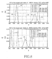
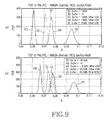
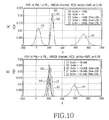
- FIGS. 8 to 10 The test results shown in FIGS. 8 to 10 are obtained by estimating the path metric based on the maximum correlation value.
- first frames allocated to the user are represented as reference characters (A) and (F).
- second frames allocated to other users are represented as reference characters (C) to (E) and (H) to (J) and third frames having no control information are represented as reference characters (B) and (G).
- FIG. 8 are graphs illustrating performance test results of a conventional TDM frame detection method when the path metric is only used.
- the path metric values for the second frames C to E and H to J allocated to other users cannot be precisely distinguished from the path metric value for the first frames A and F allocated to the mobile station.
- FIG. 9 is a graph illustrating the performance test result of a TDM frame detection method according to the first embodiment of the present invention, in which the second path metric is estimated by using Equation 1.
- the second frames C to E and H to J allocated to other users have a path metric smaller than that of the third frames B and G having no control information, so the frame detection performance may be significantly improved.
- the frames can be easily distinguished from each other regardless of the location of the mobile station, so the FAR, which is a probability of an error under the "Good" state of the CRC result, can be significantly reduced.
- FIG. 10 are graphs illustrating the performance test results of a TDM frame detection method according another embodiment of the present invention, in which the second path metric is estimated by using Equation 2.
- the second frames C to E and H to J allocated to other users have the small path metric similar to that of the third frames B and G having no control information, so the frame detection performance may be significantly improved.
- frame detection may be influenced by the location of the mobile station, the frames can be easily distinguished from each other. Thus, the FAR can be significantly reduced.
- the first embodiment of the present invention it is possible to improve reception reliability for control channels by easily detecting the TDM frame, which is allocated to each user and transmitted through the control channels in the mobile communication system providing the broadcast services.
- the TDM frame transmitted through the control channel for each user can be stably detected regardless of location variations of the mobile station and the frames can be stably received in the mobile station.
- the FAR can be reduced by simultaneously performing two schemes.
- the CRC inspection method is used in the second embodiment of the present invention in order to detect an error of a frame received in the mobile station.
- a location of a power control bit (PCB) of the F-DCCH which is commonly used for broadcast services, is randomly determined according to the long code mask allocated to each mobile station.
- the value of the power control bit transmitted from the above location may be the same during one frame. That is, in a case of a frame transmitted to a specific mobile station, since the power control bit has the same value during one frame, a large accumulated value can be obtained by accumulating the value of the power control bit.
- value accumulation is performed in a predetermined location, which is determined according to the long code of the receiver 200 regardless of the data and power control bit, so the accumulated value is set to "0" or substantially equals to "0".
- noise signals are accumulated so that the frame has a very low accumulated value.
- this embodiment of the present invention provides a method for determining whether the channel is correctly received through the F-DCCH by using the CRC inspection result and the value of he power control bit.
- FIG. 11 is a block diagram illustrating an internal structure of a DCCH receiver according to the second embodiment of the present invention.
- the structure and operation of the DCCH receiver according to the second embodiment of the present invention will be described in detail with reference to FIG. 11.
- a depuncturing unit 801 shown in FIG. 11 receives a despread symbol array r[n] from a transmitter 100 in order to depuncture the despread symbol array r[n] by using a long code mask value allocated to the mobile station.
- the depuncturing unit 801 according to an embodiment of the present invention divides a data symbol array of the depunctured symbols into two branches, in which one branch is connected to a descrambler 220 and the other branch is connected to a first absolute value calculator 802.
- the depuncturing unit 801 outputs the power control bit separately from the data.
- the value of the power control bit is not an actual value of the power control bit, but a value of a dummy bit included in the transmitter.
- a CPCCH which is a separate power control channel, is allocated to the dummy bit, so that the power control bit is not transmitted to the dummy bit through the F-DCCH which is commonly used.
- the dummy bit is inserted in order to maintain a format of data transmitted in the mobile communication system, in which the dummy bit has the same value during one frame.
- the pseudo power control bit output from the depuncturing unit 801 is also divided into two branches, in which one branch is input into a second accumulator 805 and the other branch is input into a second absolute value calculator 803.
- the descrambler 220 descrambles the data by using the long code mask, which is discretely or commonly allocated to a plurality of mobile stations for the purpose of broadcast services. Such descrambled data are input into a deinterleaver 225.
- the deinterleaver 225 deinterleaves control information and outputs the deinterleaved control information in order to prevent a burst error when transmitting the control information.
- the data output from the deinterleaver 225 are input into a channel decoder 230 so that the channel decoding is performed with respect to the data.
- the channel decoder 230 comprises a Viterbi decoder.
- the channel-decoded information is input into a CRC inspector 240 so that CRC bits of the channel-decoded information are inspected in the CRC inspector 240 in order to determine whether the error occurs in the information while the information is being transmitted through the channel.
- the CRC inspector 240 outputs the result and the decoded value of the result.
- the information output from the CRC inspector 240 is input into a frame quality bit generator 811.
- the other branched data output from the depuncturing unit 801 are input into the first absolute value calculator 802.
- the first absolute value calculator 802 calculates an absolute value of the data and sends it into the first accumulator 804.
- the first accumulator 804 accumulates the absolute values of the data during one frame and sends them to a metric generator 807 according to the present invention.
- the metric generator 807 will be described later in detail.
- the pseudo power control bit output from the depuncturing unit 801 is also divided into two branches one of which is input into the second accumulator 805.
- the second accumulator 805 accumulates the value of the pseudo power control bit during one frame and sends the accumulated value of the pseudo power control bit into the metric generator 807.
- the other branch is input into the second absolute value calculator 803.
- the second absolute value calculator 803 takes an absolute value of the pseudo power control bit and sends the absolute value to a third accumulator 806.
- the third absolute value accumulator 806 accumulates the absolute value of the pseudo power control bit during one frame and sends the accumulated absolute value to the metric generator 807.
- the metric generator 807 can generate the metric by using one of the following seven schemes. That is, the metric generator 807 may generate the metric by using the accumulated value of the pseudo power control bit, the accumulated absolute value of the pseudo power control bit, or the accumulated absolute value of the data symbols.
- the metric generator 807 can generate the metric according to Equation 7:
- Equation 7 PCB is a pseudo power control bit
- r[n] is a value which is depunctured in the depuncturing unit 801 and accumulated by means of the second accumulator 805.
- Equation 7 can be used. That is, when the depuncturing unit 801 performs the depuncturing process, the depuncturing unit 801 outputs the pseudo power control bit value by using the long code mask value thereof in one frame. Accordingly, a great accumulated value of the pseudo power control bit is represented if the frame is received in the mobile station. However, if the frame is not received in the mobile station, the accumulated value of the pseudo power control bit is very low or similar to a noise value. In addition, if the frame has no control information, only the noise components are accumulated, so that the accumulated value of the pseudo power control bit is very low.
- the metric generator 807 can output the metric according to Equation 7.
- the metric generator 807 can generate the metric according to Equation 8:
- PCB is a pseudo power control bit
- r[n] is a value which is depunctured in the depuncturing unit 801 and accumulated by means of the second accumulator 805.
- is a value which is depunctured in the depuncturing unit 801, calculated by the first absolute value calculator 802, and accumulated by means of the first accumulator 804. That is, a denominator in Equation 8 is obtained by taking an absolute value of r[n] using the first absolute value calculator 802 and accumulating the absolute value of r[n] using the first accumulator 804 when n is not the PCB.
- the metric is generated according to Equation 8, it is possible to compensate for an error which may occur in Equation 7.
- a distance between the mobile station and the base station may vary. That is, the location of the mobile station may be continuously changed.
- an absolute value of reception power may vary depending on the location of the mobile station in a cell.
- the mobile station may receive a data part and a PCB part at the same location in the cell during one frame. Therefore, it is possible to compensate for variation derived from the location of the mobile station by using a ratio of accumulated values between the data part and the PCB part.
- each frame is subject to the power control for the mobile station, so frame power may be seriously varied, causing a fading channel effect in each frame unit. If the metric is obtained according to Equation 8, it is possible to compensate for the fading channel effect in each frame unit. In addition, it is also possible to compensate for a slow fading channel effect in each frame unit, so the mobile station can adaptively deal with the channel variation.
- the metric generator 807 can generate the metric according to Equation 9:
- Equation 9 Parameters used in Equation 9 are identical to those of Equations 7 and 8, except for ⁇ which is a constant obtained through various tests. Similar to Equation 8, Equation 9 also compensates for the error which may occur in Equation 7.
- the metric generator 807 can generate the metric according to Equation 10:
- Equation 10 Parameters used in Equation 10 are identical to those of Equations 7 to 9.
- the metric is obtained by calculating a ratio of the accumulated value of the PCB to the accumulated absolute value of the PCB.
- a numerator in Equation 10 is obtained by accumulating the value of the PCB using the second accumulator 805 during one frame and a denominator in Equation 10 is obtained by taking the absolute value of the PCB using the second absolute value calculator 803 and accumulating the absolute value of the PCB using the third accumulator 806 during one frame.
- Equation 10 is similar to Equation 8, except that the accumulated absolute value of the PCB is used instead of the accumulated data value.
- the metric generator 807 can generate the metric according to Equation 11:
- Equation 11 Parameters used in Equation 11 are identical to those of Equations 7 to 10 except for ⁇ which is a constant obtained through various tests.
- the metric is obtained by subtracting an accumulated absolute value of the PCB multiplied by ⁇ from an accumulated value of the PCB.
- the antecedent term of Equation 11 signifies a value accumulated by the second accumulator 805 during one frame and the consequent term of Equation 11 signifies a value obtained by taking an absolute value of the PCB using the second absolute value calculator 803, accumulating the absolute value of the PCB using the third accumulator 806 during one frame, and multiplying the absolute value of the PCB by the constant ⁇ .
- Equation 11 is similar to Equation 9, except that the accumulated absolute value of the PCB is used instead of the accumulated data value.
- the metric generator 807 can generate the metric according to Equation 12:
- Equation 12 Parameters used in Equation 12 are identical to those of Equations 7 to 11, except for Frame which means both data and PCB.
- the metric is obtained by calculating a ratio of the accumulated value of the PCB to the accumulated absolute value of Frame.
- a numerator in Equation 12 is obtained by accumulating the value of the PCB using the second accumulator 805 during one frame.
- a denominator in Equation 12 signifies the sum of data values accumulated during one frame by using the first absolute value calculator 802 and the first accumulator 804 and PCB values accumulated during one frame by using the second absolute value calculator 803 and the third accumulator 806.
- the metric generator 807 can generate the metric according to Equation 13:
- Equation 13 Parameters used in Equation 13 are identical to those of Equations 7 to 12 except for ⁇ which is a constant obtained through various tests and Frame which means both data and PCB.
- the antecedent term of Equation 13 signifies a value accumulated by the second accumulator 805 during one frame.
- the consequent term of Equation 13 signifies the sum of data values accumulated during one frame by using the first absolute value calculator 802 and the first accumulator 804 and PCB values accumulated during one frame by using the second absolute value calculator 803 and the third accumulator 806, which is multiplied by the constant ⁇ .
- the metric generator 807 may generate the metric by using one of the above seven schemes. If the metric has been calculated, the metric value is input into a comparator 808. Upon receiving the metric value, the comparator 808 compares the metric value with a predetermined threshold value according to the above Equations.
- the dummy symbol transmitted to the power control bit has a positive real number (for example: +1)
- the metric value is larger than the predetermined threshold value
- the metric value is smaller than the predetermined threshold value
- the dummy symbol transmitted to the power control bit has a negative real number (for example: -1)
- it is determined that the decoded signal is valid when the metric value is smaller than the predetermined threshold value and it is determined that the decoded signal is invalid when the metric value is larger than the predetermined threshold value.
- the absolute value of accumulated values of the PCB part is compared with the predetermined threshold value. In this case, it is determined that the decoded signal is valid when the absolute value is larger than the predetermined threshold value and it is determined that the decoded signal is invalid when the absolute value is smaller than the predetermined threshold value.
- the above seven metrics can be replaced with the following seven metrics as shown in Equations 14 to 20, which correspond to Equations 7 to 13:
- the absolute value can be replaced with a squared absolute value.
- the predetermined threshold value for the squared absolute value is properly selected. If the Euclidean distance or the squared Euclidean distance is calculated in the Viterbi decoder by using the path metric, a cord word having a minimum path metric is output. Thus, when the metric is compared with the predetermined threshold value, the valid state of the decoded signal is interchanged with the invalid state of the decoded signal.
- the comparator 808 outputs the comparison result to a frame quality bit generator 811.
- the frame quality bit generator 811 checks the comparison result output from the comparator 808 only when the inspection result of the CRC inspector 240 represents that the decoded signal is valid. Accordingly, the frame quality bit generator 811 may generate a frame quality notification bit indicating the valid frame only when the values input into the frame quality bit generator 811 from the CRC inspector 240 and the comparator 808 are valid. Otherwise, the frame quality bit generator 811 may generate a frame quality notification bit indicating the invalid frame
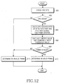
- FIG. 12 is a flowchart illustrating a procedure of detecting a frame in a mobile communication system according to a second embodiment of the present invention.
- the procedure of detecting the frame according to the second embodiment of the present invention will be described in detail with reference to FIGS. 11 and 12.
- the frame quality bit generator 811 checks the CRC bits from an output of the decoder at step 900.
- the CRC inspection may be performed through the depuncturing unit 801 and the CRC inspector 240. That is, the CRC inspector 240 performs the CRC test and outputs the result thereof. After that, the frame quality bit generator 811 determines if the CRC is good or valid at step 902. If it is determined at step 902 that the CRC is good, step 904 is performed. Otherwise, it is determined that the output of the decoder is invalid at step 912.
- the frame quality bit generator 811 calculates an accumulated value of required sections of a data part or a pseudo power control bit part during a TDM frame interval. That is, the accumulated value of the required sections is calculated by means of the first and second absolute value calculators 802 and 803 and first to third accumulators 804 to 806.
- the output of the CRC inspector 240 and the output of the comparator 808 are simultaneously generated if the first and second absolute value calculators 802 and 803 and first to third accumulators 804 to 806 are provided in hardware.
- the flowchart shown in FIG. 12 illustrates the output of the comparator after the CRC inspection step for illustrative purpose only.
- the required sections may vary depending on Equations 7 to 13.
- the calculated values are input into the metric generator 807.
- the metric generator 807 calculates the metric through one of Equation 7 to 13 by using accumulated values and the comparator 808 compares the metric value with the predetermined threshold value at step 906. If the comparison result shows the valid state of the frame, the comparator 808 generates a signal indicating the validity of the frame. Otherwise, the comparator 808 generates a signal indicating invalidity of the frame.
- the frame quality bit generator 811 determines whether the comparison result shows the valid state of the frame at step 908. That is, the frame quality bit generator 811 checks whether the signal indicating the validity of the frame is input thereto from the comparator 808. If it is determined in step 808 that the frame is valid, the frame quality bit generator 811 outputs a frame quality bit indicating the valid state of the frame at step 910. Otherwise, the frame quality bit generator 811 outputs a frame quality bit indicating the invalid state of the frame at step 912.
- this embodiment of the present invention can precisely determine the valid state and the invalid state of the TDM frame transmitted through the F-DCCH by performing the above procedure.
- this embodiment of the present invention will be described in relation to simulation results.
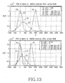
- FIG. 13 are graphs illustrating performance test results obtained based on Equation 7 of the present invention.
- FIG. 13 shows a probability density function (PDF) in various environments when the metric is obtained based on Equation 7.
- PDF is tested under the conditions that the control signal is transmitted to the mobile station, the control signal is not transmitted to the mobile station and the control signal is transmitted into other mobile stations.
- several tests are performed while varying to power when the control signal is transmitted to other mobile stations. Specifically, in a case that the control signal is transmitted to the mobile station, an Ec/lor value satisfying a frame error rate (FER) of 1% is applied.
- FER frame error rate
- the PDF test is performed while varying the Ec/lor value (for example, -12dB, -18dB and -24dB).
- the PDF test is performed while varying a location value of the mobile station (for example, 0dB and -8dB) in order to display PDF variations according to the location of the mobile station in the cell.
- the frame if the control signal is transmitted to the mobile station, the frame has curves (A) and (F). In addition, if the control signal is not transmitted to the mobile station, the frame has curves (B) and (G). If the control signal is transmitted to the other mobile station, the frame has curves (C), (D), (E), (H), (I) and (J).
- the graph shown in FIG. 13 is obtained based on Equation 7. That is, the graph shown in FIG. 13 is obtained by using the accumulated value for the PCB part in the frame. It can be understood from FIG. 13 that the PDF can be differentiated in most cases. However, the wrong TDM detection may occur if the frame transmitted to the other mobile station has a large amount of power. In addition, various threshold values must be applied according to the location of the mobile station in the cell.
- FIG. 14 are graphs graph illustrating performance test results obtained based on Equation 8 of the present invention.
- FIG. 14 shows the PDF in various environments when the metric is obtained based on Equation 8. The performance test has been conducted under the same conditions of FIG. 13.
- the frame if the control signal is transmitted to the mobile station, the frame has curves (A) and (F). In addition, if the control signal is not transmitted to the mobile station, the frame has curves (B) and (G). If the control signal is transmitted to the other mobile station, the frame has curves (C), (D), (E), (H), (I) and (J).
- the graph shown in FIG. 14 is obtained based on Equation 8. That is, the graph shown in FIG. 14 is obtained by dividing the value of Equation 7 by the accumulated value of the data part in one frame. It can be understood from FIG. 14 that the PDF can be differentiated in most cases.
- the frame having the control signal transmitted to other mobile station may have curves substantially identical to those of the frame having no control signal.
- FIG. 15 are graphs illustrating performance test results obtained based on Equation 9 of the present invention.
- FIG. 15 shows the PDF in various environments when the metric is obtained based on Equation 9. The performance test has been conducted under the same conditions of FIGS. 13 and 14.
- the frame has curves (A) and (F). In addition, if the control signal is not transmitted to the mobile station, the frame has curves (B) and (G). If the control signal is transmitted to the other mobile station, the frame has curves (C), (D), (E), (H), (I) and (J).
- the graph shown in FIG. 15 is obtained based on Equation 9. That is, the graph shown in FIG. 15 is obtained by subtracting the accumulated value of the data part in one frame from the value of Equation 7 after scaling the accumulated value of the data part.
- the term scaling refers to the accumulated value of the data part being multiplied by a constant obtained through various tests.
- the scaling constant used in FIG. 15 is 0.005.
- the PDF can be differentiated in most cases. That is, if the accumulated value of the pseudo power control bit part is large, the accumulated value of the data part is also large. Accordingly, if the metric is obtained based on the differential value between the accumulated value of the data part and the value of Equation 7, the frame having the control signal transmitted to other mobile station may be easily distinguished as compared with the frame having no control signal. In addition, it is possible to use a fixed threshold value regardless of the location of the mobile station in the cell.
- Equations 10 to 13 are not illustrated in figures, they are similar to the performance results shown in FIGS. 14 and 15 because Equations 10 to 14 represent the metrics similar to those of Equations 7 to 9.
- the mobile station can precisely determine the valid and invalid states of the frame when the TDM channel is transmitted thereto through the F-DCCH in the mobile communication system. Accordingly, when it is necessary to receive services for a long period of time, such as broadcast services, the quality of services can be improved. In addition, the cell throughput of the base station can be improved.
Landscapes
- Engineering & Computer Science (AREA)
- Computer Networks & Wireless Communication (AREA)
- Signal Processing (AREA)
- Quality & Reliability (AREA)
- Artificial Intelligence (AREA)
- Detection And Prevention Of Errors In Transmission (AREA)
- Mobile Radio Communication Systems (AREA)
- Time-Division Multiplex Systems (AREA)
Applications Claiming Priority (4)
| Application Number | Priority Date | Filing Date | Title |
|---|---|---|---|
| KR2004040140 | 2004-06-02 | ||
| KR1020040040140A KR20050114999A (ko) | 2004-06-02 | 2004-06-02 | 이동통신 시스템에서 프레임 검출 장치 및 방법 |
| KR1020040040554A KR20050115182A (ko) | 2004-06-03 | 2004-06-03 | 이동통신 시스템의 제어 채널을 통해 전송되는 시분할다중 프레임 검출 방법 및 그 장치 |
| KR2004040554 | 2004-06-03 |
Publications (2)
| Publication Number | Publication Date |
|---|---|
| EP1603265A2 true EP1603265A2 (fr) | 2005-12-07 |
| EP1603265A3 EP1603265A3 (fr) | 2008-06-25 |
Family
ID=34937172
Family Applications (1)
| Application Number | Title | Priority Date | Filing Date |
|---|---|---|---|
| EP05011918A Withdrawn EP1603265A3 (fr) | 2004-06-02 | 2005-06-02 | Dispositif et procédé pour la détection d'une trame de multiplexage par division temporelle dans un système de communication mobile |
Country Status (3)
| Country | Link |
|---|---|
| US (1) | US7327714B2 (fr) |
| EP (1) | EP1603265A3 (fr) |
| JP (1) | JP2005348412A (fr) |
Cited By (1)
| Publication number | Priority date | Publication date | Assignee | Title |
|---|---|---|---|---|
| EP1983652A4 (fr) * | 2006-01-11 | 2013-05-15 | Nec Corp | Dispositif de reception cdma et son procede de detection sfn |
Families Citing this family (13)
| Publication number | Priority date | Publication date | Assignee | Title |
|---|---|---|---|---|
| US20070140207A1 (en) * | 2005-05-31 | 2007-06-21 | Kyocera Corporation | Communication system, communication apparatus, communication method and base station |
| KR101203471B1 (ko) * | 2006-06-29 | 2012-11-21 | 삼성전자주식회사 | 네트워크 브리지에서 이더넷 프레임을 전달하는 방법 및상기 브리지 장치 |
| US8296619B2 (en) * | 2007-04-20 | 2012-10-23 | Interdigital Technology Corporation | Method and apparatus for indicating a temporary block flow to which a piggybacked ACK/NACK field is addressed |
| US20110182385A1 (en) * | 2009-07-30 | 2011-07-28 | Qualcomm Incorporated | Method and apparatus for reliability-aided pruning of blind decoding results |
| JP5299162B2 (ja) * | 2009-08-13 | 2013-09-25 | ソニー株式会社 | 受信装置、および受信方法 |
| US8516349B2 (en) | 2010-09-02 | 2013-08-20 | Microsoft Corporation | Generation and application of a sub-codebook of an error control coding codebook |
| WO2012027819A1 (fr) | 2010-09-02 | 2012-03-08 | Nortel Networks Limited | Génération et application d'un sous-livre de codes d'un livre de codes pour codage de contrôle d'erreur |
| US9344901B2 (en) * | 2013-04-16 | 2016-05-17 | Qualcomm Incorporated | Apparatus and methods of processing a protocol data unit |
| JP6253121B2 (ja) * | 2016-02-12 | 2017-12-27 | マイクロソフト テクノロジー ライセンシング,エルエルシー | 誤り制御符号化コードブックのサブコードブックの生成及び適用 |
| KR102547476B1 (ko) | 2016-07-22 | 2023-06-27 | 삼성전자주식회사 | 경로 메트릭 값 기반의 디코딩 프로세스 제어 방법, 연산 장치 및 모바일 장치 |
| CN109474377B (zh) * | 2017-09-08 | 2024-05-10 | 华为技术有限公司 | 编译码方法及装置 |
| TWI681639B (zh) * | 2018-07-19 | 2020-01-01 | 瑞昱半導體股份有限公司 | 迴旋碼解碼器及迴旋碼解碼方法 |
| US12238194B2 (en) | 2020-04-06 | 2025-02-25 | Viasat, Inc. | Multi-stage burst detection for communications systems |
Family Cites Families (16)
| Publication number | Priority date | Publication date | Assignee | Title |
|---|---|---|---|---|
| JPH02241249A (ja) | 1989-03-15 | 1990-09-25 | Nec Corp | 干渉検出方式 |
| JPH05207076A (ja) | 1991-11-25 | 1993-08-13 | Nec Corp | 受信機 |
| FI94810C (fi) * | 1993-10-11 | 1995-10-25 | Nokia Mobile Phones Ltd | Menetelmä huonon GSM-puhekehyksen tunnistamiseksi |
| JP3311252B2 (ja) | 1995-08-23 | 2002-08-05 | 沖電気工業株式会社 | 伝送速度推定装置、また、これを用いた伝送速度可変通信システム |
| GB9520445D0 (en) * | 1995-10-06 | 1995-12-06 | British Telecomm | Convolutional codes |
| JP3340618B2 (ja) * | 1996-04-19 | 2002-11-05 | 松下電器産業株式会社 | 誤り検出方法 |
| JPH1070472A (ja) | 1996-08-27 | 1998-03-10 | Toyo Commun Equip Co Ltd | ワイヤレスマイクシステム |
| AU6289998A (en) * | 1997-02-27 | 1998-09-18 | Siemens Aktiengesellschaft | Frame-error detection method and device for error masking, specially in gsm transmissions |
| US6141388A (en) * | 1998-03-11 | 2000-10-31 | Ericsson Inc. | Received signal quality determination method and systems for convolutionally encoded communication channels |
| JP3613448B2 (ja) * | 1999-06-21 | 2005-01-26 | 株式会社エヌ・ティ・ティ・ドコモ | データ伝送方法、データ伝送システム、送信装置および受信装置 |
| DE60010633T2 (de) | 1999-06-28 | 2004-09-23 | Samsung Electronics Co., Ltd., Suwon | Gerät und verfahren zur steuerung der stärke einer abwärtsverbindung in einem unterbrochenen übertragungsmodus in einem mobilen kommunikationssystem |
| JP2001292128A (ja) | 2000-04-05 | 2001-10-19 | Oki Electric Ind Co Ltd | 受信装置 |
| US6763244B2 (en) * | 2001-03-15 | 2004-07-13 | Qualcomm Incorporated | Method and apparatus for adjusting power control setpoint in a wireless communication system |
| KR101002814B1 (ko) * | 2003-10-02 | 2010-12-21 | 삼성전자주식회사 | 패킷 데이터 서비스를 제공하는 이동통신 시스템에서순방향 패킷 데이터 제어 채널 수신 장치 및 방법 |
| JP2005328317A (ja) * | 2004-05-14 | 2005-11-24 | Fujitsu Ltd | 通信装置、再送制御方法 |
| US8068530B2 (en) * | 2004-06-18 | 2011-11-29 | Qualcomm Incorporated | Signal acquisition in a wireless communication system |
-
2005
- 2005-06-02 JP JP2005163350A patent/JP2005348412A/ja active Pending
- 2005-06-02 EP EP05011918A patent/EP1603265A3/fr not_active Withdrawn
- 2005-06-02 US US11/142,353 patent/US7327714B2/en not_active Expired - Fee Related
Cited By (1)
| Publication number | Priority date | Publication date | Assignee | Title |
|---|---|---|---|---|
| EP1983652A4 (fr) * | 2006-01-11 | 2013-05-15 | Nec Corp | Dispositif de reception cdma et son procede de detection sfn |
Also Published As
| Publication number | Publication date |
|---|---|
| US20050286459A1 (en) | 2005-12-29 |
| JP2005348412A (ja) | 2005-12-15 |
| US7327714B2 (en) | 2008-02-05 |
| EP1603265A3 (fr) | 2008-06-25 |
Similar Documents
| Publication | Publication Date | Title |
|---|---|---|
| JP3866712B2 (ja) | バースト検出器 | |
| CN100461785C (zh) | 用于确定在可变速率通信系统中接收数据的速率的方法和装置 | |
| US7688915B2 (en) | Method and system for blindly detecting a discontinuously transmitted shared channel, in particular blind high speed shared control channels detection | |
| US7327714B2 (en) | Apparatus and method for detecting a time division multiplexing frame in a mobile communication system | |
| US6967998B1 (en) | Method and apparatus for monitoring transmission quality | |
| EP1114530B1 (fr) | Dispositif et procede de detection de debit de donnees pour un systeme de communication mobile | |
| US20090122891A1 (en) | Control channel detection scheme | |
| KR20000052928A (ko) | 가변 레이트 데이터를 디코딩하는 방법 및 장치 | |
| US7555069B2 (en) | Apparatus and method for receiving a forward packet data control channel in a mobile communication system supporting packet data service | |
| US7496804B2 (en) | Communications system, receiver, and method of estimating received signal quality by using bit error rate | |
| US7979782B2 (en) | Low complexity blind transport format detection | |
| KR100213876B1 (ko) | 비터비 복호기를 이용한 비트 오율 측정 장치 | |
| EP1897259B1 (fr) | Decodeur et procede pour determiner un indicateur de fiabilite de decodage | |
| JP2002528958A (ja) | 直接シーケンス符号分割多重アクセスシステムにおける転送速度検出 | |
| US20120113853A1 (en) | Method and apparatus for blind transport format detection using discontinuous transmission (dtx) detection | |
| US6952463B2 (en) | Method of blind transport format detection based on power transition | |
| GB2389021A (en) | Blind transport format detection with preselection of candidate transport formats | |
| US7505534B1 (en) | Method for determination of discontinuous transmission, frame erasure, and rate | |
| US20160212644A1 (en) | Method of estimating ber values in a wireless communication system | |
| CN101151836B (zh) | 检测数据网络中数据块的块长度的方法、装置和系统 | |
| KR20050115182A (ko) | 이동통신 시스템의 제어 채널을 통해 전송되는 시분할다중 프레임 검출 방법 및 그 장치 | |
| JP2006311553A (ja) | スクランブルされたn個のコード・ブロックからの1つの選択 | |
| KR20050114999A (ko) | 이동통신 시스템에서 프레임 검출 장치 및 방법 | |
| KR100939422B1 (ko) | 디코더 메트릭에 의거한 블라인드 전송 포맷 검출 | |
| Wang et al. | Optimal blind transport format detection for the UMTS uplink |
Legal Events
| Date | Code | Title | Description |
|---|---|---|---|
| PUAI | Public reference made under article 153(3) epc to a published international application that has entered the european phase |
Free format text: ORIGINAL CODE: 0009012 |
|
| 17P | Request for examination filed |
Effective date: 20050602 |
|
| AK | Designated contracting states |
Kind code of ref document: A2 Designated state(s): AT BE BG CH CY CZ DE DK EE ES FI FR GB GR HU IE IS IT LI LT LU MC NL PL PT RO SE SI SK TR |
|
| AX | Request for extension of the european patent |
Extension state: AL BA HR LV MK YU |
|
| PUAL | Search report despatched |
Free format text: ORIGINAL CODE: 0009013 |
|
| AK | Designated contracting states |
Kind code of ref document: A3 Designated state(s): AT BE BG CH CY CZ DE DK EE ES FI FR GB GR HU IE IS IT LI LT LU MC NL PL PT RO SE SI SK TR |
|
| AX | Request for extension of the european patent |
Extension state: AL BA HR LV MK YU |
|
| AKX | Designation fees paid |
Designated state(s): AT BE BG CH CY CZ DE DK EE ES FI FR GB GR HU IE IS IT LI LT LU MC NL PL PT RO SE SI SK TR |
|
| STAA | Information on the status of an ep patent application or granted ep patent |
Free format text: STATUS: THE APPLICATION HAS BEEN WITHDRAWN |
|
| 18W | Application withdrawn |
Effective date: 20090507 |