EP1603368A2 - Schaltungsanordnung zum Betreiben einer Beleuchtungseinrichtung - Google Patents
Schaltungsanordnung zum Betreiben einer Beleuchtungseinrichtung Download PDFInfo
- Publication number
- EP1603368A2 EP1603368A2 EP05090122A EP05090122A EP1603368A2 EP 1603368 A2 EP1603368 A2 EP 1603368A2 EP 05090122 A EP05090122 A EP 05090122A EP 05090122 A EP05090122 A EP 05090122A EP 1603368 A2 EP1603368 A2 EP 1603368A2
- Authority
- EP
- European Patent Office
- Prior art keywords
- current
- circuit
- inrush current
- circuit arrangement
- arrangement according
- Prior art date
- Legal status (The legal status is an assumption and is not a legal conclusion. Google has not performed a legal analysis and makes no representation as to the accuracy of the status listed.)
- Withdrawn
Links
Images

Classifications
-
- B—PERFORMING OPERATIONS; TRANSPORTING
- B61—RAILWAYS
- B61L—GUIDING RAILWAY TRAFFIC; ENSURING THE SAFETY OF RAILWAY TRAFFIC
- B61L5/00—Local operating mechanisms for points or track-mounted scotch-blocks; Visible or audible signals; Local operating mechanisms for visible or audible signals
- B61L5/12—Visible signals
- B61L5/18—Light signals; Mechanisms associated therewith, e.g. blinders
- B61L5/1809—Daylight signals
- B61L5/1881—Wiring diagrams for power supply, control or testing
-
- H—ELECTRICITY
- H05—ELECTRIC TECHNIQUES NOT OTHERWISE PROVIDED FOR
- H05B—ELECTRIC HEATING; ELECTRIC LIGHT SOURCES NOT OTHERWISE PROVIDED FOR; CIRCUIT ARRANGEMENTS FOR ELECTRIC LIGHT SOURCES, IN GENERAL
- H05B45/00—Circuit arrangements for operating light-emitting diodes [LED]
- H05B45/30—Driver circuits
- H05B45/37—Converter circuits
-
- H—ELECTRICITY
- H05—ELECTRIC TECHNIQUES NOT OTHERWISE PROVIDED FOR
- H05B—ELECTRIC HEATING; ELECTRIC LIGHT SOURCES NOT OTHERWISE PROVIDED FOR; CIRCUIT ARRANGEMENTS FOR ELECTRIC LIGHT SOURCES, IN GENERAL
- H05B45/00—Circuit arrangements for operating light-emitting diodes [LED]
- H05B45/50—Circuit arrangements for operating light-emitting diodes [LED] responsive to malfunctions or undesirable behaviour of LEDs; responsive to LED life; Protective circuits
-
- B—PERFORMING OPERATIONS; TRANSPORTING
- B61—RAILWAYS
- B61L—GUIDING RAILWAY TRAFFIC; ENSURING THE SAFETY OF RAILWAY TRAFFIC
- B61L2207/00—Features of light signals
- B61L2207/02—Features of light signals using light-emitting diodes [LEDs]
Definitions
- the invention relates to a circuit arrangement for operating a lighting device, in particular an LED signal generator, according to the preamble of claim 1.
- the following description refers by way of example in the Essentially on LED signalers, which instead of incandescent signalers in many areas, especially in railway signaling, increasingly be applied.
- the invention also encompasses safety-relevant lighting devices for a wide variety of applications and based on a variety of light sources, such as Fluorescent tubes or OLED.
- LEDs are comparatively inexpensive, durable and bright. When replacing incandescent bulbs by LEDs is cost reasons sought for the control and monitoring the incandescent lamps to use existing facilities. There are significant problems, because the electrical behavior of LEDs is fundamentally different from that of incandescent lamps.
- For monitoring the correct functions of the Beacons are in the parent facility supervisor, usually based on supervisor relay provided. These relays require a safe suit higher current than in normal operation.
- the pull-in current can also above the pickup value of a circuit used in the circuit Fuse, allowing a continuous operation of the monitoring relay with this pull-in current is not possible.
- the invention is based on the object, a circuit arrangement of the generic type which makes it possible modern bulbs with conventional parent facilities, In particular, monitoring devices to use.
- the object by the characterizing Characteristics of claim 1 solved. After that contains the circuit arrangement a circuit part having an inrush current sufficient to the response of the monitoring device sure. Due to the additional circuit part is the current consumption for a short time directly or shortly after switching on until above a threshold the monitoring device increases. The raised Power is maintained as long as it is from the monitoring circuit is needed.
- the time duration for the current increase according to claim 2 so short that the maximum continuous current of the parent Institution is not exceeded, so that Do not address any fuses that may be present.
- an R / C element for current-time characteristic simulation be formed of an incandescent lamp.
- the behavior of a light bulb will be complete simulated.
- the circuit part according to claim 5 also part of a for example, from DE 101 02 352 A1 known current-voltage characteristic simulation or one for example DE 102 21 573 A1 known light intensity-voltage characteristic simulation to be a light bulb.
- FIGS. 1 to 3 illustrate current I-time t characteristics for the switch-on phases of incandescent lamps 1 and LED signal transmitters 2 and 3. Shown also are the attraction threshold 4 and the holding threshold 5 of a monitoring relay and an upper current limit 6 of a superordinate device, for example is predetermined by a fuse. It can be seen that in the incandescent lamp variant - Figure 1 - immediately after switching on the bulb during a period .DELTA.t G flows a current that exceeds the threshold 4 of the supervisory relay. Consequently, it is ensured that the monitor relay attracts. Only after tightening the monitoring relay reaches the, z. B. melt fuse due, upper current limit 6 a value below the threshold threshold 4. Since the incandescent current does not fall below the holding threshold 5 of the monitor relay, the relay remains in the attracted state.
- the It characteristic curve 2 shown in FIG. 2 for an LED signal generator has no increased inrush current, so that the starting threshold 4 for the monitoring relay is not exceeded. There remains a current difference ⁇ I L , so that the monitor relay can not respond. Consequently, a simple replacement of incandescent lamps by LEDs leads to a failure of the monitoring circuit, which can not be tolerated.
- This problem is solved by a circuit part which is connected in parallel with the LED signal generator and generates an additional current flow during a time period ⁇ t L.
- the period of time .DELTA.t L of this current peak 7 is dimensioned such that the upper current limit 6, the z. B. is specified by a fuse, is not exceeded.
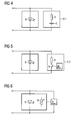
- FIG. 4 shows a first exemplary embodiment of a circuit arrangement with a circuit part 8.1 to increase the current during the switch-on phase.
- the circuit part 8.1 is to the LED signal generator 9 connected in parallel and includes a series circuit from a resistor R and a capacitor C. This R / C combination allows a relatively accurate cold-thread replica a filament lamp. In this way it is achieved the I-t curve is approximately that shown in FIG Inrush current 1 corresponds to an incandescent lamp.
- Figure 6 shows a variant in which an already existing Wiring of the LED signal generator 9 with a resistor R " analogous to the circuit parts 8.1 and 8.2 of Figure 4 or
- the invention is not limited to the above Embodiments. Rather, a number of Variants conceivable, which are also different in principle Execution of the features of the invention make use.
- the circuits are not on DC limited.
- the basic principle is of course also on alternating current applicable.
Landscapes
- Engineering & Computer Science (AREA)
- Mechanical Engineering (AREA)
- Circuit Arrangement For Electric Light Sources In General (AREA)
Abstract
Description
- Figur 1
- den zeitlichen Stromverlauf in der Einschaltphase bei einer Glühlampe,
- Figur 2
- den zeitlichen Stromverlauf in der Einschaltphase bei einem LED-Signalgeber,
- Figur 3
- den zeitlichen Stromverlauf in der Einschaltphase bei einem LED-Signalgeber mit dem erfindungsgemäßen Schaltungsteil und
- Figuren 4 bis 6
- Ausführungsvarianten für den Schaltungsteil.
Claims (5)
- Schaltungsnordung zum Betreiben einer Beleuchtungseinrichtung, insbesondere eines LED-Signalgebers (9), im Zusammenwirken mit einer übergeordneten Einrichtung, insbesondere einer Überwachungseinrichtung, die einen Einschaltstrom vorgibt,
gekennzeichnet durch
einen Schaltungsteil (8.1, 8.2) zur Einstellung des Einschaltstromes bis oberhalb einer Ansprechschwelle der übergeordneten Einrichtung während einer Zeitdauer (ΔtL). - Schaltungsanordnung nach Anspruch 1,
dadurch gekennzeichnet, dass die Zeitdauer (ΔtL) für den Einschaltstrom derart kurz bemessen ist, dass der maximale Dauerstrom der übergeordneten Einrichtung nicht überschritten wird und gegebenenfalls eine stromüberwachende Einrichtung, insbesondere eine Stromsicherung, nicht anspricht. - Schaltungsanordnung nach einem der vorangehenden Ansprüche,
dadurch gekennzeichnet, dass der Schaltungsteil (8.1) als Parallelschaltung zu der Beleuchtungseinrichtung mit einem R/C-Glied zur Strom-Zeit-Kennliniennachbildung (1) einer Glühlampe ausgebildet ist. - Schaltungsanordnung nach Anspruch 1 oder 2,
dadurch gekennzeichnet, dass der Schaltungsteil (8.1) als Parallelschaltung zu der Beleuchtungseinrichtung mit einem während der Zeitdauer (ΔtL) zuschaltbaren Wiederstand (R') ausgebildet ist. - Schaltungsanordnung nach einem der vorangehenden Ansprüche,
dadurch gekennzeichnet, dass der Schaltungsteil (8.1, 8.2) in eine Schaltung zur Strom-Spannungs-Kennliniennachbildung oder zur Lichtstärke-Spannungs-Kennliniennachbildung einer Glühlampe eingebunden ist.
Applications Claiming Priority (2)
| Application Number | Priority Date | Filing Date | Title |
|---|---|---|---|
| DE102004027351 | 2004-06-01 | ||
| DE102004027351A DE102004027351B3 (de) | 2004-06-01 | 2004-06-01 | Schaltungsanordnung zum Betreiben einers LED-Signalgebers |
Publications (2)
| Publication Number | Publication Date |
|---|---|
| EP1603368A2 true EP1603368A2 (de) | 2005-12-07 |
| EP1603368A3 EP1603368A3 (de) | 2006-06-07 |
Family
ID=34938444
Family Applications (1)
| Application Number | Title | Priority Date | Filing Date |
|---|---|---|---|
| EP05090122A Withdrawn EP1603368A3 (de) | 2004-06-01 | 2005-05-04 | Schaltungsanordnung zum Betreiben einer Beleuchtungseinrichtung |
Country Status (3)
| Country | Link |
|---|---|
| EP (1) | EP1603368A3 (de) |
| DE (1) | DE102004027351B3 (de) |
| NO (1) | NO20052573L (de) |
Cited By (2)
| Publication number | Priority date | Publication date | Assignee | Title |
|---|---|---|---|---|
| CN101975899A (zh) * | 2010-09-20 | 2011-02-16 | 河南辉煌科技股份有限公司 | 转辙机动作电流曲线检测方法 |
| EP2124507A3 (de) * | 2008-05-23 | 2014-05-28 | Siemens Aktiengesellschaft | Signalgeber für ein LED-Lichtsignal |
Families Citing this family (2)
| Publication number | Priority date | Publication date | Assignee | Title |
|---|---|---|---|---|
| EP2463174B1 (de) * | 2010-12-09 | 2013-10-30 | Siemens Schweiz AG | Vorrichtung und Verfahren zur Realisierung eines Glühlampenersatzes für ein Lichtsignal |
| SE539826C2 (sv) | 2014-10-29 | 2017-12-12 | Scania Cv Ab | Compensation unit configured to be connected between a control unit and at least one LED lamp |
Family Cites Families (9)
| Publication number | Priority date | Publication date | Assignee | Title |
|---|---|---|---|---|
| DE59406833D1 (de) * | 1993-11-05 | 1998-10-08 | Siemens Schweiz Ag | Schaltungsanordnung für eisenbahn-lichtsignalanlagen |
| CA2225005A1 (en) * | 1997-12-17 | 1999-06-17 | Gelcore Llc | Led lamp with a fault-indicating empedance-changing circuit |
| US6597179B2 (en) * | 1999-11-19 | 2003-07-22 | Gelcore, Llc | Method and device for remote monitoring of LED lamps |
| US6392553B1 (en) * | 2000-08-22 | 2002-05-21 | Harmon Industries, Inc. | Signal interface module |
| DE10102352C2 (de) * | 2001-01-19 | 2003-02-20 | Siemens Ag | Schaltungsanordnung zur Kennlinienanpassung einer Leuchtdiodenanordnung, Leuchtdioden-Signallampe und Leuchtsignalanordnung sowie deren Verwendung |
| DE10107578A1 (de) * | 2001-02-17 | 2002-08-29 | Hella Kg Hueck & Co | Lichtanlage für Kraftfahrzeuge |
| DE10146008C1 (de) * | 2001-09-19 | 2003-04-24 | Hella Kg Hueck & Co | Schaltungsanordnung zur Simulation der elektrischen Eigenschaften einer Glühlampe |
| DE10215472B4 (de) * | 2002-04-09 | 2007-08-02 | Hella Kgaa Hueck & Co. | Verfahren zum Betrieb einer Beleuchtungseinrichtung für Fahrzeuge mit einer mindestens eine Leuchtdiode aufweisenden Lampenanordnung sowie Beleuchtungseinrichtung für Fahrzeuge |
| DE10221573B4 (de) * | 2002-05-08 | 2004-03-18 | Siemens Ag | Schaltungsanordnung zum Betreiben eines Leuchtzeichens |
-
2004
- 2004-06-01 DE DE102004027351A patent/DE102004027351B3/de not_active Expired - Fee Related
-
2005
- 2005-05-04 EP EP05090122A patent/EP1603368A3/de not_active Withdrawn
- 2005-05-27 NO NO20052573A patent/NO20052573L/no not_active Application Discontinuation
Cited By (3)
| Publication number | Priority date | Publication date | Assignee | Title |
|---|---|---|---|---|
| EP2124507A3 (de) * | 2008-05-23 | 2014-05-28 | Siemens Aktiengesellschaft | Signalgeber für ein LED-Lichtsignal |
| CN101975899A (zh) * | 2010-09-20 | 2011-02-16 | 河南辉煌科技股份有限公司 | 转辙机动作电流曲线检测方法 |
| CN101975899B (zh) * | 2010-09-20 | 2012-08-22 | 河南辉煌科技股份有限公司 | 转辙机动作电流曲线检测方法 |
Also Published As
| Publication number | Publication date |
|---|---|
| NO20052573D0 (no) | 2005-05-27 |
| EP1603368A3 (de) | 2006-06-07 |
| DE102004027351B3 (de) | 2006-01-19 |
| NO20052573L (no) | 2005-12-02 |
Similar Documents
| Publication | Publication Date | Title |
|---|---|---|
| DE69816958T2 (de) | Schaltungsanordnung mit dabei passender signalleuchte | |
| DE69826825T2 (de) | Schaltungsanordnung und zugehörige signalleuchte | |
| EP1360088B1 (de) | Lichtanlage für kraftfahrzeuge | |
| DE10215486C1 (de) | Beleuchtungseinrichtung für Fahrzeuge | |
| DE10358447B3 (de) | Beleuchtungseinrichtung | |
| EP2918144A2 (de) | Verfahren und vorrichtung zur datenübertragung über eine lastleitung und beleuchtungssystem | |
| DE102006055610A1 (de) | Verfahren zur gepulsten Bestromung von Glühlampen in Kraftfahrzeugen | |
| EP0992961B1 (de) | Schaltungsanordnung zum Betreiben eines Leuchtzeichens | |
| EP1233654A1 (de) | Schaltungsanordnung und Verfahren zur Kennlinienanpassung einer Leuchtdiode | |
| EP3082383B1 (de) | Verfahren und vorrichtung zur bestimmung einer lebenserwartungs-information eines led-moduls | |
| DE3616506C2 (de) | Verfahren und Vorrichtung zur Überwachung elektrischer Verbraucher | |
| EP1603368A2 (de) | Schaltungsanordnung zum Betreiben einer Beleuchtungseinrichtung | |
| EP1473976B1 (de) | Schnittstelle für Digitale- und Netzspannungssignale und Verfahren zur Auslegung solch einer Schnittstelle | |
| DE102018107500B4 (de) | Lampentreiber für eine LED Lampe und LED Lampe zum Einsetzen in eine Leuchtstofflampenleuchte | |
| DE102006018308B4 (de) | Schaltungsanordnung für ein Fahrzeugbordnetz zum Simulieren von Blinkleuchten mit Glühlampen bei einer Verwendung von Blinkleuchten mit Leuchtdioden | |
| WO2017191270A1 (de) | Scheinwerfer mit schaltungsanordnung zur simulation eines laststroms aus einem bordnetz | |
| EP2080667A1 (de) | Verfahren zur Ausfallkontrolle von Lichtfunktionen in einem Kraftfahrzeugbordnetz | |
| EP4077048B1 (de) | Fahrzeugscheinwerfer umfassend ein schaltungssystem | |
| WO2017191280A1 (de) | Schaltungsanordnung und verfahren zur simulation eines laststroms aus einem bordnetz | |
| DE3937978C2 (de) | Einschaltstrombegrenzer | |
| DE10121380A1 (de) | Elektronisch abgesicherte Stromversorgung für Schaltungsgruppen, Anzeigevorrichtung für eine sich ändernde Information | |
| EP1416774B1 (de) | Ansteuerung für mindestens eine Leuchtdiode an einem Kraftfahrzeug | |
| DE102015006705B3 (de) | Leuchtmittelsteuerung | |
| DE102013003766B3 (de) | Verfahren zum Ersetzen von Kleinpolrelais in Gleich-/Wechselstromübertragungen der Eisenbahnsignaltechnik | |
| DE1210364B (de) | Blinklichtsignaleinrichtung |
Legal Events
| Date | Code | Title | Description |
|---|---|---|---|
| PUAI | Public reference made under article 153(3) epc to a published international application that has entered the european phase |
Free format text: ORIGINAL CODE: 0009012 |
|
| AK | Designated contracting states |
Kind code of ref document: A2 Designated state(s): AT BE BG CH CY CZ DE DK EE ES FI FR GB GR HU IE IS IT LI LT LU MC NL PL PT RO SE SI SK TR |
|
| AX | Request for extension of the european patent |
Extension state: AL BA HR LV MK YU |
|
| PUAL | Search report despatched |
Free format text: ORIGINAL CODE: 0009013 |
|
| AK | Designated contracting states |
Kind code of ref document: A3 Designated state(s): AT BE BG CH CY CZ DE DK EE ES FI FR GB GR HU IE IS IT LI LT LU MC NL PL PT RO SE SI SK TR |
|
| AX | Request for extension of the european patent |
Extension state: AL BA HR LV MK YU |
|
| 17P | Request for examination filed |
Effective date: 20060710 |
|
| 17Q | First examination report despatched |
Effective date: 20061120 |
|
| AKX | Designation fees paid |
Designated state(s): AT BE BG CH CY CZ DE DK EE ES FI FR GB GR HU IE IS IT LI LT LU MC NL PL PT RO SE SI SK TR |
|
| 17Q | First examination report despatched |
Effective date: 20061120 |
|
| 17Q | First examination report despatched |
Effective date: 20061120 |
|
| STAA | Information on the status of an ep patent application or granted ep patent |
Free format text: STATUS: THE APPLICATION IS DEEMED TO BE WITHDRAWN |
|
| 18D | Application deemed to be withdrawn |
Effective date: 20070829 |