EP1603752B1 - Sachet a encre et cartouche a encre comprenant le sachet a encre - Google Patents
Sachet a encre et cartouche a encre comprenant le sachet a encre Download PDFInfo
- Publication number
- EP1603752B1 EP1603752B1 EP04720739A EP04720739A EP1603752B1 EP 1603752 B1 EP1603752 B1 EP 1603752B1 EP 04720739 A EP04720739 A EP 04720739A EP 04720739 A EP04720739 A EP 04720739A EP 1603752 B1 EP1603752 B1 EP 1603752B1
- Authority
- EP
- European Patent Office
- Prior art keywords
- ink
- bag
- case
- holding member
- ink bag
- Prior art date
- Legal status (The legal status is an assumption and is not a legal conclusion. Google has not performed a legal analysis and makes no representation as to the accuracy of the status listed.)
- Expired - Lifetime
Links
- 238000007599 discharging Methods 0.000 claims abstract description 36
- 239000000463 material Substances 0.000 claims description 20
- 238000003466 welding Methods 0.000 claims description 11
- 229920001971 elastomer Polymers 0.000 claims description 8
- 238000007789 sealing Methods 0.000 claims description 7
- 229920001296 polysiloxane Polymers 0.000 claims description 6
- 229910052731 fluorine Inorganic materials 0.000 claims description 4
- 239000011737 fluorine Substances 0.000 claims description 4
- 125000000484 butyl group Chemical group [H]C([*])([H])C([H])([H])C([H])([H])C([H])([H])[H] 0.000 claims description 2
- PXGOKWXKJXAPGV-UHFFFAOYSA-N Fluorine Chemical compound FF PXGOKWXKJXAPGV-UHFFFAOYSA-N 0.000 claims 1
- 239000000976 ink Substances 0.000 description 483
- 238000010586 diagram Methods 0.000 description 45
- 238000010276 construction Methods 0.000 description 21
- 238000000034 method Methods 0.000 description 21
- 238000003860 storage Methods 0.000 description 15
- 229910052782 aluminium Inorganic materials 0.000 description 13
- XAGFODPZIPBFFR-UHFFFAOYSA-N aluminium Chemical compound [Al] XAGFODPZIPBFFR-UHFFFAOYSA-N 0.000 description 13
- 238000002474 experimental method Methods 0.000 description 13
- 239000005001 laminate film Substances 0.000 description 11
- 230000002706 hydrostatic effect Effects 0.000 description 9
- 229920002379 silicone rubber Polymers 0.000 description 8
- 238000011156 evaluation Methods 0.000 description 7
- 230000008569 process Effects 0.000 description 6
- 230000000994 depressogenic effect Effects 0.000 description 5
- 239000004945 silicone rubber Substances 0.000 description 5
- 229920002943 EPDM rubber Polymers 0.000 description 4
- 230000006835 compression Effects 0.000 description 4
- 238000007906 compression Methods 0.000 description 4
- 239000012530 fluid Substances 0.000 description 4
- 230000007246 mechanism Effects 0.000 description 4
- YCKRFDGAMUMZLT-UHFFFAOYSA-N Fluorine atom Chemical compound [F] YCKRFDGAMUMZLT-UHFFFAOYSA-N 0.000 description 3
- 230000008859 change Effects 0.000 description 3
- 230000005611 electricity Effects 0.000 description 3
- 238000002347 injection Methods 0.000 description 3
- 239000007924 injection Substances 0.000 description 3
- 239000010410 layer Substances 0.000 description 3
- 238000005259 measurement Methods 0.000 description 3
- 238000004064 recycling Methods 0.000 description 3
- 230000002829 reductive effect Effects 0.000 description 3
- 239000011347 resin Substances 0.000 description 3
- 229920005989 resin Polymers 0.000 description 3
- 238000000926 separation method Methods 0.000 description 3
- 239000002699 waste material Substances 0.000 description 3
- 229920005549 butyl rubber Polymers 0.000 description 2
- 238000007600 charging Methods 0.000 description 2
- 238000009820 dry lamination Methods 0.000 description 2
- 238000003780 insertion Methods 0.000 description 2
- 230000037431 insertion Effects 0.000 description 2
- 229920001684 low density polyethylene Polymers 0.000 description 2
- 239000004702 low-density polyethylene Substances 0.000 description 2
- 238000004519 manufacturing process Methods 0.000 description 2
- 238000005192 partition Methods 0.000 description 2
- 230000001681 protective effect Effects 0.000 description 2
- 230000002441 reversible effect Effects 0.000 description 2
- 230000003068 static effect Effects 0.000 description 2
- 239000002344 surface layer Substances 0.000 description 2
- OKTJSMMVPCPJKN-UHFFFAOYSA-N Carbon Chemical compound [C] OKTJSMMVPCPJKN-UHFFFAOYSA-N 0.000 description 1
- 241001070941 Castanea Species 0.000 description 1
- 235000014036 Castanea Nutrition 0.000 description 1
- 239000004952 Polyamide Substances 0.000 description 1
- 238000010521 absorption reaction Methods 0.000 description 1
- 230000004308 accommodation Effects 0.000 description 1
- 230000005540 biological transmission Effects 0.000 description 1
- 230000015572 biosynthetic process Effects 0.000 description 1
- 238000009835 boiling Methods 0.000 description 1
- 229910052799 carbon Inorganic materials 0.000 description 1
- 238000006243 chemical reaction Methods 0.000 description 1
- 239000003086 colorant Substances 0.000 description 1
- 230000007797 corrosion Effects 0.000 description 1
- 238000005260 corrosion Methods 0.000 description 1
- 238000005336 cracking Methods 0.000 description 1
- 230000007547 defect Effects 0.000 description 1
- 238000004090 dissolution Methods 0.000 description 1
- 239000013013 elastic material Substances 0.000 description 1
- 238000007786 electrostatic charging Methods 0.000 description 1
- 230000003628 erosive effect Effects 0.000 description 1
- 229920000840 ethylene tetrafluoroethylene copolymer Polymers 0.000 description 1
- 238000005429 filling process Methods 0.000 description 1
- 229920001903 high density polyethylene Polymers 0.000 description 1
- 239000004700 high-density polyethylene Substances 0.000 description 1
- 230000009545 invasion Effects 0.000 description 1
- 239000007788 liquid Substances 0.000 description 1
- 229910052751 metal Inorganic materials 0.000 description 1
- 239000002184 metal Substances 0.000 description 1
- 238000012986 modification Methods 0.000 description 1
- 230000004048 modification Effects 0.000 description 1
- 230000035515 penetration Effects 0.000 description 1
- 229920002647 polyamide Polymers 0.000 description 1
- 238000003825 pressing Methods 0.000 description 1
- 229910001285 shape-memory alloy Inorganic materials 0.000 description 1
- 239000010935 stainless steel Substances 0.000 description 1
- 229910001220 stainless steel Inorganic materials 0.000 description 1
- 230000005068 transpiration Effects 0.000 description 1
- 230000032258 transport Effects 0.000 description 1
- 239000011800 void material Substances 0.000 description 1
Images


Classifications
-
- B—PERFORMING OPERATIONS; TRANSPORTING
- B41—PRINTING; LINING MACHINES; TYPEWRITERS; STAMPS
- B41J—TYPEWRITERS; SELECTIVE PRINTING MECHANISMS, i.e. MECHANISMS PRINTING OTHERWISE THAN FROM A FORME; CORRECTION OF TYPOGRAPHICAL ERRORS
- B41J2/00—Typewriters or selective printing mechanisms characterised by the printing or marking process for which they are designed
- B41J2/005—Typewriters or selective printing mechanisms characterised by the printing or marking process for which they are designed characterised by bringing liquid or particles selectively into contact with a printing material
- B41J2/01—Ink jet
- B41J2/17—Ink jet characterised by ink handling
- B41J2/175—Ink supply systems ; Circuit parts therefor
- B41J2/17503—Ink cartridges
- B41J2/17553—Outer structure
-
- B—PERFORMING OPERATIONS; TRANSPORTING
- B41—PRINTING; LINING MACHINES; TYPEWRITERS; STAMPS
- B41J—TYPEWRITERS; SELECTIVE PRINTING MECHANISMS, i.e. MECHANISMS PRINTING OTHERWISE THAN FROM A FORME; CORRECTION OF TYPOGRAPHICAL ERRORS
- B41J2/00—Typewriters or selective printing mechanisms characterised by the printing or marking process for which they are designed
- B41J2/005—Typewriters or selective printing mechanisms characterised by the printing or marking process for which they are designed characterised by bringing liquid or particles selectively into contact with a printing material
- B41J2/01—Ink jet
- B41J2/17—Ink jet characterised by ink handling
- B41J2/175—Ink supply systems ; Circuit parts therefor
- B41J2/17503—Ink cartridges
- B41J2/17513—Inner structure
-
- B—PERFORMING OPERATIONS; TRANSPORTING
- B41—PRINTING; LINING MACHINES; TYPEWRITERS; STAMPS
- B41J—TYPEWRITERS; SELECTIVE PRINTING MECHANISMS, i.e. MECHANISMS PRINTING OTHERWISE THAN FROM A FORME; CORRECTION OF TYPOGRAPHICAL ERRORS
- B41J2/00—Typewriters or selective printing mechanisms characterised by the printing or marking process for which they are designed
- B41J2/005—Typewriters or selective printing mechanisms characterised by the printing or marking process for which they are designed characterised by bringing liquid or particles selectively into contact with a printing material
- B41J2/01—Ink jet
- B41J2/17—Ink jet characterised by ink handling
- B41J2/175—Ink supply systems ; Circuit parts therefor
- B41J2/17503—Ink cartridges
- B41J2/1752—Mounting within the printer
- B41J2/17523—Ink connection
-
- B—PERFORMING OPERATIONS; TRANSPORTING
- B41—PRINTING; LINING MACHINES; TYPEWRITERS; STAMPS
- B41J—TYPEWRITERS; SELECTIVE PRINTING MECHANISMS, i.e. MECHANISMS PRINTING OTHERWISE THAN FROM A FORME; CORRECTION OF TYPOGRAPHICAL ERRORS
- B41J2/00—Typewriters or selective printing mechanisms characterised by the printing or marking process for which they are designed
- B41J2/005—Typewriters or selective printing mechanisms characterised by the printing or marking process for which they are designed characterised by bringing liquid or particles selectively into contact with a printing material
- B41J2/01—Ink jet
- B41J2/17—Ink jet characterised by ink handling
- B41J2/175—Ink supply systems ; Circuit parts therefor
- B41J2/17503—Ink cartridges
- B41J2/17556—Means for regulating the pressure in the cartridge
-
- B—PERFORMING OPERATIONS; TRANSPORTING
- B41—PRINTING; LINING MACHINES; TYPEWRITERS; STAMPS
- B41J—TYPEWRITERS; SELECTIVE PRINTING MECHANISMS, i.e. MECHANISMS PRINTING OTHERWISE THAN FROM A FORME; CORRECTION OF TYPOGRAPHICAL ERRORS
- B41J2/00—Typewriters or selective printing mechanisms characterised by the printing or marking process for which they are designed
- B41J2/005—Typewriters or selective printing mechanisms characterised by the printing or marking process for which they are designed characterised by bringing liquid or particles selectively into contact with a printing material
- B41J2/01—Ink jet
- B41J2/17—Ink jet characterised by ink handling
- B41J2/175—Ink supply systems ; Circuit parts therefor
- B41J2/17503—Ink cartridges
- B41J2/17513—Inner structure
- B41J2002/17516—Inner structure comprising a collapsible ink holder, e.g. a flexible bag
Definitions
- the present invention relates to an ink bag and an ink cartridge structure.
- An ink-jet recording apparatus is used extensively for image formation apparatuses (called also as image recording apparatus) such as printers, facsimiles, copiers, and the like.
- An ink-jet recording apparatus carries out recording of images on a sheet by discharging ink from a recording head.
- sheet is not limited to paper but also includes OHP sheet, and the like.
- sheet represents the medium on which images are formed and is also called as medium to be recorded or recording medium, or recording paper.
- An ink-jet recording apparatus has various advantageous features such as capability of recording high-definition images at high speed, low running cost, little noise, and capability of recording color images easily by using multiple color inks.
- Japanese Laid-Open Patent Application 10-202901 in which ink is filled in a hard case of rectangular shell, or there exists a device described in Japanese Laid-Open Patent Application 10-202900 having a flexible bag-like tank equipped with an ink exit and a chassis (case) provided with an opening so as to allow loading and unloading of the ink tank to and from the chassis through the opening.
- FIG. 1 there is a known ink cartridge formed of an ink storage part 501 for storing ink, a cylindrical case 502 accommodating wherein the ink storage part 501, and a cover lid member 503 covering the front face of the cylindrical case 502.
- a holding member 504 integral to the ink storage part 501 such that the holding member 504 includes a sealed ink filling opening 505 of cylindrical form used for filling the ink and an ink supplying opening 506 of cylindrical form for supplying the ink.
- the holding member 504 is fixed upon the cylindrical case 502 by pushing the holding member 504 in such a manner that a protrusion part 504a of the holding member 504 catches a hole 502a provided on the wall midway of the cylindrical case 502.
- the ink storage part 501 forms a frame body 511 together with the holding member 504 and a film-like member 512 formed of an inner resin film and an outer aluminum film is welded upon the frame body 511 at the outside thereof.
- the size of the ink cartridge is increasing, while such an increase of the size of the ink cartridge raises the problem in that mere discarding of used ink cartridge as in the case of the ink cartridge described in the Japanese Laid Open Patent Application 10- 202901 causes the problem of serious waste of resources.
- the ink tank In the case the ink cartridge is plugged into the main body of the ink-jet recording apparatus from an upward direction with such an orientation such that the ink supplying opening (supply opening) faces the downward direction, the ink tank is held in the chassis part in a somewhat stabilized state.
- the construction in which the ink cartridge is plugged into the main body from the front side with such an orientation that the ink supplying opening faces a lateral or horizontal direction hereinafter, such a construction will be called "front loading construction"
- the ink tank is held in the chassis in the inclined state.
- the ink storage part in the form of a bag such that the entire ink storage part has flexibility.
- the ink storage part is constructed in the form of flexible bag
- a protection cover for improving load/unload operability to and from the recording apparatus main body and further for improving durability, while such a necessity raises the problem of providing a construction enabling easy loading and unloading of the flexible ink bag having a protective cover at the time of refilling of the ink.
- US 5,805,189 discloses a device for fluid supply of a micro-metering device for ink print heads.
- the micro-metering device is subdivided into a fluid supply container and a fluid compartment by a partition wall.
- the fluid supply container contains a flexible bag body which is welded to the partition wall.
- the preamble of claim 1 is based on this document.
- the present invention is made in view,of the problems noted above and has its object of providing an ink bag wherein waste of unused ink is minimized and can be easily mounted to a protective cover detachably and with stability. Further, the present invention provides an ink cartridge comprising such an ink bag.
- an ink bag holding ink therein comprising:
- said bag has a width(W) -to-height(H) ratio (W/H) falling in the range of 1 ⁇ W/H ⁇ 1.5 or 1.5 ⁇ 1.
- the ink filling opening and the ink discharge port of the holding member are preferably located generally at the central part of the edge of the bag main body. Further, it is preferable that the holding member of the ink bag is held, when accommodated in the cartridge case, in such a state that the ink discharge port is located generally at the center of the cartridge case in a height direction.
- the ink filling opening is sealed by way of welding in the state in which ink is filled in the bag main body.
- the holding member is provided in a longer edge of the bag main body.
- an outer circumference surface of the ink discharging port has a stepped part for engaging with an engaging piece provided to the foregoing cap member.
- the elastic member is formed of a columnar member of a rubber material such as silicone rubber, fluorine rubber, a butyl rubber, and the like.
- the cap member is formed of a cylindrical member having a flange part for holding down the elastic member, and it is preferable that the cylindrical part has plural engaging piece bent inward.
- the ink cartridge may include at least first and second case parts having similar external form, wherein these first and second case parts can be assembled together to form a single cartridge case or decomposed into individual parts.
- the ink cartridge may be loaded from a front direction into an ink jet recording apparatus.
- ink filling method for filling ink to an ink bag used with the ink cartridge of the present invention. It should be noted that the ink is filled from the ink filling opening in the state in which the holding member of the ink bag is engaged with the first case part.
- ink refilling method for refilling ink to an ink bag used with the ink cartridge of the present invention, wherein the ink is refilled from the ink discharging port in the state in which the holding member of the ink bag is engaged with the first case part.
- the ink refilling method refills the ink to the ink bag used with the ink cartridge of the present invention in such a manner that there is formed a rupture part or puncturing to a part of the bag main body of the ink bag and by sealing the rupture part after refilling of the ink through this rupture part.
- a manufacturing method of the ink cartridge may include the step of attaching the second case part to the first case part after engaging the holding member of the ink bag filled with ink to the first case part.
- a recycling method of the ink cartridge may recycle the ink cartridge by disassembling the first and case parts from each other, removing the ink bag by disengaging the holding member of the ink bag from the first case part, and then engaging the holding member of the ink bag filled with the ink with the engaging part of the first case part, and further assembling the first and second case parts.
- the holding member is fixed to one edge of the bag main body having a generally square form by thermal welding process in such a manner that it is held by the case detachably.
- the ink cartridge is the one that accommodates therein the ink bag of the present invention having the ink bag holding member.
- Another object of the present invention is to provide an ink cartridge allowing easy reuse of the case and simultaneously capable of supplying ink stably without causing leak.
- Figure 2 is a diagram showing an appearance of an ink cartridge according to the present invention in an oblique view
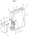
- Figure 3 is a schematic oblique view showing the ink cartridge of Figure 2 in the state in which a third case part is removed
- Figure 4 is a front cross-sectional view of the same ink cartridge.
- this ink cartridge 1 includes an ink bag 2 filled with ink and a case 3 accommodating the ink bag 2.
- the case 3 is formed of a first case part 11, a second case part 12 and a third case part 13, wherein the first case part 11 and the second case part 12 form together a case part acting as a protection cover protecting a side of the ink bag 2.
- the case 3 accommodating the ink bag 2 is split into the first case part 11 and the second case part 12 along a plane parallel to the ink supply direction (ink discharge direction).
- Figure 5 is a side view diagram of the same ink bag
- Figure 6 is a diagram showing the ink bag of Figure 5 as viewed from a downward direction in the state filled with the ink
- Figure 7 is a cross-sectional diagram of the aluminum laminate film constituting the bag main body of the ink bag
- Figure 8 is a side view diagram of a holding member of the ink bag
- Figure 9 is a diagram showing the holding member of Figure 8 as viewed from a rear direction
- Figure 10 is a diagram showing the holding member of Figure 8 from a front direction
- Figure 11 is a cross-section diagram showing an ink discharge port of the ink bag
- Figure 12 is a cross- sectional diagram of a cap member provided to the ink discharge port of Figure 11
- Figure 13 is a diagram showing the cap member as viewed from a front direction thereof.
- the ink bag 2 includes a flexible bag main body 21 of an aluminum laminate film having a generally square form (rectangular form in the present example) and a holding member 22 of a resin material is fixed (welded) to the longer edge of the bag main body.
- the bag main body 21 is formed of an aluminum laminate film 30 having a structure in which a dry lamination 26, an aluminum film 27, a dry lamination 28, and a PA (polyamide) film 29 are stacked consecutively on a LDPE (low-density polyethylene) base 25.
- a dry lamination 26 an aluminum film 27, a dry lamination 28, and a PA (polyamide) film 29 are stacked consecutively on a LDPE (low-density polyethylene) base 25.
- LDPE low-density polyethylene
- the bag main body 21 there is provided no frame body for maintaining the form of the bag, contrary to the conventional bag, and as a result, the bag has high flexibility for the entire part thereof. With this, the present invention can minimize the waste ink remaining in the bag unused.
- the bag main body 21 is formed of the aluminum laminate film 30 in the present example, the material used for the bag main body 21 is by no means limited to the foregoing. Yet, it is desirable to form the bag main body with a material including at least the aluminum laminate film.
- the ratio (W/H) of the width W to the height H of the bag main body 21 is preferable to fall within the range of 1 ⁇ W/H ⁇ 1.5 or 1.5 ⁇ 1 in view of securing sufficient hydrostatic pressure and minimizing the ink residual amount.
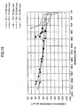
- the form of the bag main body 21 is determined to have an oblong shape (width W being larger than height H) as shown in Figure 14 .
- three kinds of bag main bodies are prepared in the experiment, 1 one having the height H ⁇ width W of 90 ⁇ 116 (1:1.29), 2 one having the height H ⁇ width W of 70 ⁇ 106 (1:1.5), and 3 one having the height H ⁇ width W of 50 ⁇ 126 (1:2.52). Further, two cases (thin type and thick tyre) having different thicknesses are prepared 2 for the case 3.
- the use of the hydrostatic pressure of about 0(gf/cm 2 ) is preferable at the ink discharge port.
- the width-to-height ratio (W/H) of the bag main body 21 falls within the range of 1 - 1.5.
- the holding member 22 constitutes a unitary connection part 32 for welding the bag main body 21 to one side of the flange part 31 as shown in Figures 8 through 10 , and a hollow ink filling opening 33 and a hollow ink discharge port 34 are formed to the other side of the flange part 31 as a unitary body (represented in the state before the welding).
- connection part 32 has a generally chestnut form by tapering both end parts (ends of the longer edges) of the holding member 22 as shown in Figure 9 . Further, a depression 32a is formed at the circumference surface. With this, it becomes possible to weld the aluminum laminate films 30 and 30 forming the bag main body 21 to the circumference surface of the connection part 32 without interruption.
- the ink filling opening 33 there is formed a pierce hole 35 used for filling the ink such that the hole 35 penetrates through the flange part 31 and also through the connection department 32, and the ink filling opening 33 is sealed (indicated in Figures 5 and 6 as seal part 36) by welding after filling the ink to the ink bag 2.
- seal part 36 By sealing the ink filling opening 33 by the thermal welding process, a reliable seal is obtained easily.
- the ink discharge port 34 has a cylindrical part 37 and a seal member holding part 38 forming a unitary body thereto, and a compartment 39 is formed between the cylindrical part 37 and the seal member holding part 38.
- an ink outlet hole 40 is formed in the cylindrical part 37 so as to penetrate through the flange part 31 and the connection department 32, and an opening 41 is formed in the seal member holding part 38 for inserting an elastic member 45 that seals the ink outlet hole 40.
- a stepped part 42 is formed to the circumference surface so as to mount a cap member between the cylindrical part 37 and the seal member holding part 38.
- the elastic member 45 is inserted into the opening 41 of the seal member holding part 38 of the ink outlet port 34 for sealing the ink outlet hole 40, and the elastic member 45 is covered with a cap member 46.
- the elastic member 45 has a form capable of maintaining seal and may have any of columnar form (circular section), triangular columnar form, a square columnar form, a pentagram columnar form, a hexagonal columnar form, a heptagonal columnar form, an octagonal columnar form, and the like.
- the cap member 46 has a cylindrical part 47 having a flange part 47a holding down a rim part of the elastic member 45 as shown in Figures 12 and 13 , wherein there is formed a hole 48 at the inner circumferential surface of the flange part 47a for plugging in a supply needle from the side of the recording apparatus. Further, plural engaging pieces 49 bent inward are formed in the cylindrical part 47. It should be noted that the form of the hole 48 is not limited to circle but any of triangle, square, pentagon, hexagon, heptagon, octagon, and the like may be used.
- the cylindrical part 37 and the holding part 38 of the ink discharge port 34 is formed of a material that does not exert influence on the properties of the ink such as high density polyethylene. With this, dissolution of the cylindrical part 37, and the like, formed with the outlet hole 40 and exposed constantly to the ink, into the ink is prevented.
- the elastic member 45 is formed of a material not exerting influence to the properties of the ink, such as silicone or a rubber material based on silicone. With this, the problem that the elastic member forming the seal member, which is constantly exposed to the ink, is dissolved into the ink and causes clogging is eliminated.
- this elastic member 45 enables the supply of the ink to the recording apparatus while maintaining the sealed state, when a hollow supply needle 111 is stabbed from the side of the recording apparatus as the ink introduction means used for introducing ink into the recording apparatus.
- the elastic member 45 is required to maintain the sealed state with reliability even when the hollow needle 111 is drawn out after stabbing, in view of the possibility that the hollow needle 111 is left in the stabbed state or the hollow needle 111 once stabbed is left after being pulled out.
- this hollow needle 111 is a cylindrical member formed with an ink introduction path 112 therein and has an ink injection hole 113 formed at the distal circumferential surface.
- the needle can be formed to have a sharp point at the tip end thereof, and it becomes possible to pierce the needle 111 into to the elastic member 45 easily without causing defect or void therein. Further, there occurs no problem that the elastic member 45 is damaged and the damaged piece cause clogging of the ink introduction hole 113.
- the cap member 46 is forming with a material, such as stainless steel that does not exert influence on the properties of the ink. With this, it becomes possible to prevent erosion or corrosion even in the case the flange part 47a contacting the elastic member 45 has contacted with the ink.
- the elastic member 45 to which the hollow needle 111 is inserted and pulled out, is required to restore the original sealed state when the hollow needle 111 is pulled out for avoiding ink leakage. Therefore, it is preferable that the elastic member 45 is inserted into the opening 41 of the holding part 38 in the state compressed in the diametrical direction.
- the elastic member 45 is held, after being inserted into the opening 41 of the holding part 38, by the flange part 47a of the cap member 46, while the cap member 46 is held on the circumference of the holding part 38 as a result of engagement of the engaging piece 49 with the stepped part 42.
- the thickness t of the elastic member 45 is equal to or smaller than the depth (height) H of the opening 41 of the holding part 38, it becomes no longer possible to hold the elastic member 45 by the cap member 46.
- the compression of the elastic member 45 in the thickness direction is excessive, there is a risk that the cap member 46 may come off with the restoration force of the elastic member 45.
- the thickness t of the elastic member 45 and the depth H of the opening 41 of the holding part 38 to which the inserts elastic member 45 is inserted is changed variously with each other and evaluation was made with regard to the transmission of the light.
- a silicone rubber was used for the material of the elastic member 45.
- Table 3 shows the result of the experiment.
- Table 3 Thickness t of the elastic member Depth H of holding part H/t evaluation 2.8 1.65 0.59 ⁇ 2.6 1.75 0.67 ⁇ 2.4 1.85 0.77 ⁇ 2.2 1.95 0.89 ⁇ 2.1 20.5 0.98 ⁇ 2.0 2.10 1.03 ⁇
- the ratio (t: H) between the thickness of the elastic member 45 and the depth H of the opening 41 of and holding part 38 falls in the range of 1:0.77 - 1:1.
- the elastic member 45 it is necessary for the elastic member 45 to set the relationship between the diameter of the hollow needle 111 and the diameter of the elastic member appropriately in view of the fact that the hollow needle 111 is stabbed thereto and pulled out therefrom, such that damaging of the elastic member 45 is avoided.
- Table 4 shows the result of the experiment.
- Table 4 Diameter d of hollow needle Outer diameter D of elastic member D/d evaluation 1.28 2.56 2 ⁇ 3.20 2.5 ⁇ 3.84 3.0 ⁇ 5.20 4 ⁇ 8.96 7 ⁇ 12.80 10 ⁇ 15.36 12 ⁇
- the ratio (d: D) between the diameter d of the hollow needle and the outer diameter D of the elastic member is preferable to set the ratio (d: D) between the diameter d of the hollow needle and the outer diameter D of the elastic member to fall in the range of 1:3 - 1:10.
- the elastic member 45 it is necessary to set the relationship between the diameter of the hollow needle 111 and the thickness of the elastic member appropriately, in view of the fact that the hollow needle 111 is inserted and pulled out and that the hollow needle 111 has to penetrate through the elastic member 45, that invasion of the hollow needle 111 is not hindered and that the sealed state is maintained even when the hollow needle 111 is drawn out.
- Table 5 summarizes the result of the experiment.
- Table 5 Diameter d of hollow needle Thickness t of elastic member t/d evaluation 1.28 1.8 1.41 ⁇ 2.0 1.56 ⁇ 2.3 1.8 ⁇ 3.0 2.34 ⁇ 3.5 2.73 ⁇ 4.0 3.13 ⁇ 4.5 3.5 ⁇ 5.0 3.91 ⁇ 5.5 4.30 ⁇
- the ratio (t/d) is less than 1.5, the elastic member 45 becomes too thin and easily undergoes damaging upon insertion of the hollow needle 111 into the elastic member 45. Further, it was confirmed that the.hole formed after drawing out the hollow needle 111 is not completely closed. On the other hand, when the ratio exceeds 3.5, the resistance at the time of stabbing the hollow needle 111 into the elastic member 45 for penetration becomes too large.
- the ink discharge port 34 of the holding member 22 is located generally at the central part of the ink bag 2 in the height direction as shown in Figure 4 .
- the flow of ink inside the bag main body 21 of the ink bag 2 becomes smooth when using the ink cartridge 1 in the upright state (the state of Figure 2 ) as compared with the case of Figure 1 in which the ink exit is provided with deviation to one end of the cartridge and, it becomes possible to use out the ink more or less, without leaving unused ink.
- engagement parts 51 and 52 are provided to the holding member 22 as a unitary body for engaging with a catch nail provided on a first case part 11 as will be described later. Further, the sidewall of the flange part 31 corresponding to the engagement parts 51 and 52 is formed with grooves 31a and 31b respectively in correspondence to the engagement parts 51 and 52.
- the ink bag 2 has a construction in which the holding member 22 is fixed to an edge of the flexible bag main body 21 of generally quadrilateral form, and the holding member 22 is provided with an ink filling opening 33 used for filling the bag main body 21 with ink and an ink discharge port 34 for discharging the ink inside the bag main body.
- the ink discharge port 34 of the holding member 22 is located generally at the center of ink bag 2 in the height direction as shown in Figure 4 . Further, the ink discharge port 34 is formed such that the ink discharge port 34 is located generally at the center of the case 3 when the ink bag 2 is held in the ink cartridge 1 as shown in Figure 2 . With this, the flow of ink inside the bag main body 21 of the ink bag 2 becomes smooth when using the ink cartridge 1 in the upright state (the state of Figure 2 ), as compared with the case in which the ink exit is provided with deviation to one end as shown in Figure 1 , and it becomes possible to use out the ink with certainty.
- the engagement parts 51 and 52 are formed on the holding member 22 as a unitary body for engagement with catch nails provided to the first case part 11 as will be explained later. Further, the groove 31a and 31b are formed on the side surface of the flange part 31 in correspondence to the engagement parts 51 and 52. As a result, the contact area of the first case part 11 and the second case part 12 side is reduced, and a more stabilized holding is achieved at the side of the case 3.
- the ink bag 2 is attached with the holding member 22, which constitutes the ink bag holding member of the present invention, such that the holding member 22 is fixed to an edge of the generally quadrilateral flexible bag main body 21, the holding member 22 including the ink filling opening 33 for filling the bag main body 21 with ink and the ink discharge port 34 for discharging the ink inside the bag main body.
- the holding member 22 includes the engaging parts 51, 52 for holding the ink bag 2 in the cartridge case 3, and it becomes possible to mount the ink bag 2 detachably to the case 3 serving for the protection cover easily and with stability while minimizing the ink remaining in the bag unused.
- the distal end part of the ink discharge port 34 of the holding member 22 is equipped with the elastic member 45 that sealing the opening and the cap member 46 that holds down the elastic member 45, reliable seal is formed by the restoration force of the elastic member 45 and leakage of the ink is eliminated even when the ink cartridge 1 is mounted and dismounted to and from the recording apparatus main body repeatedly and the supply needle (used for the ink introducing means for introducing the ink into the recording apparatus) of the recording apparatus is stabbed into the ink discharge port 34 repeatedly, and it becomes possible to supply the ink stably to the recording apparatus.
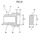
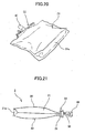
- Figure 19 is a side view diagram of the ink bag
- Figure 20 is an oblique view diagram showing the same ink bag in the state filled with ink
- Figure 21 is a bottom view diagram of the ink bag of Figure 20 .
- this ink bag 2 includes the bag body 21 of two aluminum laminate films 30 and 30, wherein there is further provided a rear part (bottom part) 21a at the rear side also formed of the aluminum laminate film.
- a rear part (bottom part) 21a at the rear side also formed of the aluminum laminate film.
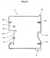
- Figure 22 is a side view diagram of the first case part 11 of the ink cartridge 1
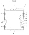
- Figure 23 is a side view diagram of the second case part 12 of the ink cartridge 1.
- the case 3 of the ink cartridge 1 is formed by assembling the first case part 11 and the second case part 12 of generally the same form divided out from a single, generally rectangular body, wherein the third case part 13 is attached to the front lower part thereof.
- a depressed part 61 and a hooking part 62 in the rear side thereof for facilitating gripping at the time of mounting and dismounting of the ink cartridge 1 to and from the recording apparatus body.
- an opening 73 on the front side thereof in alignment with the ink discharge port 34 to the main body of the ink-jet recording apparatus.
- the first case part 11 has a generally rectangular external form and includes, on its circumferential part, a depressed part 61A and a hooking part 62A respectively in the form of dividing the depressed part 61 and the hooking part 62 into halves, a cutout part 63A for forming a space allowing entrance of the ink filling device for conducting filling of the ink by the ink filling device in the state in which the ink bag 2 is held by the first case part 11 and the second case part 12, and the guide parts 64 and 65 used for loading to the recording apparatus main body or for loading to the ink filling device, in the form of a unitary body.
- engaging parts 66a, 66b and 66c for engagement with the catching nails of the second case part 12 as will be described later.
- positioning parts 67 and 68 for positioning the holding member 22 in order to hold the holding member 22 of ink bag 2.
- catching nails 71 and 72 for holding engaging projections 51 and 52 of the holding member 22. It should be noted that these positioning parts 67 and 68 and the catching nails 71 and 72 constitute the'holding means or engage holding means (means for holding by causing engagement) that holds the holding member 22 of the ink bag 2.
- the first case part 11 is formed with a depression 79 for engagement with a catching nail of the third case part 13 at the time of attaching the third case part 13.
- the second case part 12 has an external appearance generally similar to that of the first case part 11 as shown in Figure 23 and includes, on its circumferential part, a depressed part 61B and a hooking part 62B respectively in the form of dividing the depressed part 61 and the hooking part 62 into halves, a cutout part 63B for forming a space allowing entrance of the ink filling device for conducting filling of the ink by the ink filling device in the state in which the ink bag 2 is held by the first case part 11 and the second case part 12, and distinction means 84 of protrusions indicating the color of the ink filled in the ink bag 2 of the ink cartridge 1.
- engaging parts 86a, 86b and 86c for engagement respectively with the engaging parts 66a, 66b and 66c of the first case part 12 as in the form of a unitary body. Furthermore, on the inner wall surface of the second case part 12; there are formed engaging parts 87 and 88 having grooves for engagement with the holding member 22 of the ink bag 2.
- a 1/4 arc part 73B that forms a part of the opening 73 in the front side of the first case part 12 (the front side at the time of loading to the apparatus main body).
- the second case part 12 is formed with a depression 89 for engagement with a catching nail of the third case part 13 at the time of attaching the third case part 13.
- the third case part 13 is inserted into the cutout parts 63A and 63B of the first case part 11 and the second case part 12 at the front side where the ink supply is made in the state in which the first case part 11 and the second case part 12 are assembled.
- This third case part 13 is provided with catching nails 91 and 92 for engagement respectively with the engagement depressions 79 and 89 of the first case part 11 and the second case part 12 and further includes a 1/2 arc part 73 C that forms a part of the aforementioned opening 73.
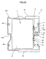
- the ink cartridge 1 is manufactured (assembled) as shown in Figure 24 by urging the holding member 22 of the ink bag 2 while positioning by using the positioning parts 67 and 68 of the first case part 11.
- the catching nails 71 and 72 of the first case part 11 engage with the projections 51 and 52 of the holding member 22 of the ink bag 2 respectively, and thus, the holding member 22 is held on the first case part 11.
- the second case part 12 is placed on the first case part 11 and the first case part 11 and the second case part 12 are pressed with each other.
- the catching nails 86a - 86c of the second case part 12 cause engagement with the engaging parts 66a - 66c of the first case part 11, and the assembling body (see Figure 3 ) of the first case part 11 and the second case part 12 is obtained.
- the third case part13 is fitted upon the first case part 11 and the second case part 12 such that the catching nails 91 and 92 of the third case part 13 cause engagement with the corresponding depressions 79 and 89 of the first case part 11 and the second case part 12.
- the third case part 13 is removed and the 2nd case part 12 and the first case part 11 are disassembled with a reverse procedure.
- the third case part 13 and the first case part 11 and the second case part 12 are easily disassembled, because they in the lightly engaged state by the catching nails and the corresponding depressions.
- ink injection can be performed in the state in which the ink bag 2 is held by the first case part 11, and thus, it becomes possible to supply the ink while confirming the condition of the ink bag 2. Further, because the ink bag 2 is held by the first case part 11 during the procedure of filling of the ink, the ink bag 2 is held in the stabilized state at the time of filling the ink.
- a thermal pressure head is urged to the ink filling opening 33 from both sides such that the ink filling opening 33 is sealed as a result of the welding process caused by the thermal pressure head.
- a hollow filling needle is plugged in to the ink discharge port 34, and the ink is supplied from outside. With this, the ink is filled in the bag main body 21.
- this procedure may be applied to the ink bag 2 itself in a stand alone state, or in the state in which the ink bag 2 is held by the first case part 11 as mentioned before.
- the rupture part or punctured part is sealed with a seal member after the refilling process.
- the ink filling opening 33 has a sufficient length, it is possible to cut the sealing part 36 and conduct the refilling of the ink through the ink filling opening 33 similarly to the initial filling process. Thereafter, the ink filling opening 33 is sealed a thermal welding process.
- the ink cartridge case 3 is assembled similarly as noted before, and it becomes possible to obtain an ink cartridge 1 accommodating the ink bag 2.
- the ink cartridge 1 of the present invention is constructed in a manner capable of being disassembled and reassembled by using the first case part holding the holding member of the ink bag, the second case part having an external form similar to that of the first case part and the third case part engaging with the first and second case parts in the assembled state thereof.
- replacement of the ink bag can be conducted easily.
- the attitude of the ink bag is stabilized even in the case the front loading construction is employed, and stable ink supply becomes possible.
- the present invention is applicable also to the case in which the ink cartridge 1 is loaded from the front side in the horizontal state.
- the embodiment of Figure 25 reinforces the engagement between the catching nail 91 and the first case part 11 and the second case part 12 of the third case part 13 by sticking a label 101 on the outside of the first case part 11 and the second case part 12. With this, it becomes possible to prevent dropping of the third case part 13 even in the case the ink cartridge 1 is inserted and removed frequently.
- Figure 26 fixes the first case part 11 and the second case part 12 by tightening a screw member 102. With this, disassembling of the case 3 is prevented even in the case in which the ink cartridge 1 is inserted and removed frequently.
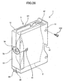
- cutout parts 69A and 69B respectively on the first case part 11 and the second case part 12 so as to be located at the lateral side of the discharge port 34 of the ink bag 2 and/or the cap member 42 provided at the distal end part of the ink discharge port 34.
- the third case part 13 is also formed with a cutout part 99 at the lateral side of the ink discharge port 34 of the ink bag 2 and/or the cap member 42 provided at the distal end part of the ink discharge port 34.
- the needle 111 is stabbed into the in ink discharge port 34 of the ink cartridge 1 from the side of the recording apparatus body as shown in Figure 28 for achieving connection between the ink bag 2 and the ink supply system of the ink-jet recording apparatus, wherein there is provided a needle guard 112 in the side of the recording apparatus so as to surround the needle 111 for protection of the needle 111.
- Figure 31 is a diagram showing the ink-jet recording apparatus of the present invention in a perspective view from a front direction thereof
- Figure 32 is a diagram showing an ink cartridge loading part of the ink-jet recording apparatus of Figure 31 in the state in which the cover is opened
- Figure 33 is a schematic diagram showing the overall construction of the mechanism part of the ink-jet recording apparatus
- Figure 34 is the a diagram showing the mechanism part in detail.
- this ink-jet recording apparatus includes an apparatus main body 201, a sheet feed tray 202 for loading a sheet set to the apparatus main body 201, and a sheet ejection tray 203 attached to the apparatus main body 201 for accumulating the sheet recorded with images.
- the top cover 211 of the apparatus main body 201 forms a generally flat surface, and the front cover of the apparatus main body 201 has a front surface 212 inclined obliquely in the rear bottom direction with respect to the foregoing top surface.
- this inclined front surface 212 there are provided a sheet discharging tray 203 and also a sheet feeding tray 202 so as to project in the forward (the front side) direction.
- an ink cartridge loading part 204 at an end part of the front surface 212 so as to project from the foregoing front surface 212 in the forward direction under the top cover 211, and an operation part 205 including various operation keys and indicators is provided on the top surface of this ink cartridge loading part 204.
- This ink cartridge loading part 204 is further provided with a front cover 215 opened and closed for loading and unloading the ink cartridge 1.
- a carriage 233 is held movably in a main scanning direction by a guide rod 231 held laterally by a pair of side boards provided at the and left and right but not illustrated and a stay 232 as shown in Figures 33 and 34 , wherein the carriage is moved in the direction indicated by arrows in Figure 34 by a main scanning motor not illustrated.
- a recording head 234 formed of four ink-jet heads respectively ejecting ink droplets of yellow (Y), cyan (C), magenta (M) and black (Bk) in such a manner that the ink ejection nozzles are aligned in the direction crossing the main scanning direction. Thereby, the ink droplets are ejected in the downward direction.
- piezoelectric actuator such as piezoelectric element
- a thermal actuator that uses phase change such as boiling of liquid film caused by an electricity-to-heat conversion element such a resistance heater
- shape memory alloy actuator that uses metal phase change caused by temperature change
- electrostatic actuator using static electricity and the like
- the carriage 233 carries sub tanks 235 of the respective colors for supplying the inks to the recording head 234.
- the ink is supplied to the sub tank 235 from the ink discharge port 34 of the ink bag 2 of the ink cartridge 1, which is loaded to the ink cartridge loading part 205, via an ink supply tube not illustrated.
- a sheet feed part for feeding the sheets 242 loaded on the sheet storage part (pressure board) 241 of the sheet feeding tray 203 one by one, wherein the sheet feed part includes a half-circle roller (sheet feed roller) 243 supplying the sheet 242 one at a time from the sheet loading part 241 and a separation pad 244 opposing the sheet feed roller 243 and formed of a material of large friction coefficient, and this separation pad 244 is urged toward the sheet feed roller 243.
- sheet feed roller half-circle roller
- a sheet transportation part for transporting the sheet 242 supplied from the foregoing sheet feed part underneath the recording head 234, wherein the sheet transpiration part includes a transportation belt 251 transporting the sheet 242 with electrostatic absorption, a counter roller 252 that transports the sheet 242 fed from the sheet feed part through the guide 245 by sandwiching the same together with the transportation belt 251, a transportation guide 253 for changing the direction of the sheet 242 supplied vertically in the upward direction by about 90 degrees for causing the sheet to imitate with the transportation belt 251, and a end pressure roller 255 urged to the conveyance belt 251 with a pressing member 254. Further, there is provided a charging roller 256 for electrostatic charging of the surface of the transportation belt 251.
- the transportation belt 251 is an endless belt laid between a transportation roller 257 and a tension roller 258 and circles in the belt transportation direction. It should be noted that this transportation belt 251 may include a surface layer part acting as a sheet adhering surface and formed of a resin material such as the one having a thickness of 40 ⁇ m and not processed with resistance control such as an ETFE pure material and a back layer part of the same material as the surface layer part and processed with resistance control carbon (middle resistance layer or ground layer).
- a surface layer part acting as a sheet adhering surface and formed of a resin material such as the one having a thickness of 40 ⁇ m and not processed with resistance control such as an ETFE pure material and a back layer part of the same material as the surface layer part and processed with resistance control carbon (middle resistance layer or ground layer).
- a guide member 261 is disposed in the reverse side of the transportation belt 251 in correspondence to the recording region in which recording is made on the sheet by the recording head 234.
- a sheet discharging part for discharging the sheet 242 recorded with images by the recording head 234 by a separation nail 271 for separating the sheet 242 from the transportation belt 251, a sheet discharging roller 272 and a sheet discharging roller 273. Further, there is provided a sheet discharging tray 203 underneath the sheet discharging roller 272.
- a sheet feed unit 281 for both side recording on the rear side of the apparatus main body 201 in a detachable manner, wherein the sheet feed unit 281 for both side recording takes up the sheet 242 returned as a result of counter rotation of the transportation belt 251 and turns the sheet over. Thereafter, the sheet is fed between the counter roller 252 and the transportation belt 251 again. Also, there is provided a hand sheet feed part 282 above the sheet feed unit 281 for both side recording.
- the sheet 242 is separated one by one from the sheet feed part, wherein the sheet 242 fed in the generally upward direction is guided with the guide 245 and is transported by being sandwiched between the transportation belt 251 and the counter roller 252.
- the sheet is further guided with the transportation guide 253 at the top part thereof and is urged to the transportation belt 251 with the pressure roller 255 at the tip end part.
- the transportation direction is changed by about 90 degrees.
- the transportation belt 257 is charged with electricity by the charging roller 256, and the sheet 242 is transported by the transportation belt 251 in the state adhered thereto by the static electricity.
- the recording operation is terminated and the sheet 242 is discharged to the discharging tray 203.
- the ink-jet recording apparatus is equipped with the ink cartridge 1 of the present invention, it becomes possible to exchange the ink bag 2 inside the ink cartridge 1 when the ink therein is used up by replacing only the ink bag 2 inside the cartridge 1 by disassembling the case 3. Further, such a construction allows stable ink supply even in the case the ink cartridge 1 is loaded from the front side in the upright state, and thus, it is possible to exchange the ink cartridge 1 easily even in the case in which the upper part of the apparatus main body 201 is occupied as in the case of the ink-jet recording apparatus being accommodated in a rack or the top surface of the ink jet apparatus main body 201 is used to support some other object.
- the present invention has been explained with regard to the example of the ink-jet recording apparatus of shuttle type in which the carriage scans the recording sheet
- the present invention is applicable also to the ink-jet recording apparatus of line type equipped with a line type head.
- the ink-jet recording apparatus of the present invention is applicable to other various apparatuses such as a facsimile device, a copying apparatus, printer/fax/copier complex machine, and the like, in addition to the ink-jet printer.
- the ink bag of the present invention includes a flexible bag main body of generally quadrilateral form and a holding member fixed to an edge of the flexible bag main body, wherein the holding member is provided with an ink filling opening for fills ink to the bag main body, an ink discharge port for discharging the ink in the bag main body and further with an engaging part for holding the ink bag to the cartridge case in which the ink bag is accommodated.
- the ink cartridge of the present invention includes at least first and second case parts of similar external form in such a manner that the first and second case parts can be assembled with each other and decomposed into individual pieces and holds the holding member of the ink bag of the present invention at the engagement holding means provided to the first case part as a result of causing engagement.
- the cartridge is easily assembled and decomposed and the remaining of unused ink is minimized.
- the ink bag can be attached and detached easily to and from the case of the ink cartridge.
- An ink-jet recording apparatus has a construction in which loading of the ink cartridge of the present invention is possible from the front side of the apparatus. Thus, it becomes possible to replace only the ink bag when the ink in the ink cartridge is used up. Further, it becomes possible to supply the ink stably.
- the ink is filled from the ink filling opening in the state in which the holding member of the ink bag is held to the first case part and thus, it becomes possible to fill the ink easily in a stabilized state.
- the ink is filled from the ink discharge port in the state in which the holding member of the ink bag is held to the first case part. Thereby, it becomes possible to refill the ink easily in a stabilized state.
- a rupture part or puncturing is provided to a part of the bag main body of the ink bag and the rupture part is sealed after ink is filled into the bag main body from this rupture part or puncturing, and because of this, it becomes possible to refill the ink easily.
- the holding member of the ink bag filled with the ink is held to the first case part and then the second case part is attached to the first case part.
- the ink cartridge can be assembled easily.
- the first and second case parts are disassembled from each other and the ink bag is removed by dismounting the holding member of the ink bag from the first case part. Further, the holding member of the ink bag filled with the ink is held to the engagement holding part of the first case part and the first and second case parts are assembled with each other.
- the ink cartridge case is not wasted and recycled effectively.
- the holding member in the ink bag of the present invention is such a member used for accommodating the ink bag main body having flexibility into the ink cartridge and includes an ink filling opening for fills ink into the bag main body, an ink discharge port for discharging the ink inside the bag main body, and further an engaging part held by the engaging means provided to at least one of the case parts forming a half body of the cartridge case.
- the ink bag that having the ink bag holding member is accommodated therein, and thus, it becomes possible to stably accommodate the ink bag having flexibility therein.
- the ink cartridge of the present invention can be loaded from the front direction into an ink-jet recording apparatus, and thus, it becomes possible to replace only the ink bag when the ink the ink cartridge is used up.
- a holding member is fixed to a bag main body having flexibility, wherein the holding member is provided with an ink filling opening for filling ink into the ink bag main body and an ink discharge port for discharging the ink inside the bag main body. Further, the holding member is provided with an engaging part for holding the ink bag to the cartridge case. As a result, remaining of unused ink is minimized and the ink bag can be attached detachably to the case easily and stably. Thereby, stable ink supply is realized.
- the ink cartridge includes a case formed of at least first and second case parts having similar external form wherein these first and second case parts can be assembled and disassembled to and form each other. Further, the holding member of the ink bag of the present invention is held at the engagement holding means provided to the first case part. Thus, assembling and disassembling is made easily and remaining of unused ink is minimized. Further, it becomes possible to attach the ink bag to the case removably, stably and easily.
- the present invention is based on Japanese Priority Patent Applications 2003-074520 filed on March 18, 2003 , 2003-076676 filed on March 20, 2003 , 2003-076663 filed on March 20, 2003 and 2003-183326 filed on June 26, 2003 .
Landscapes
- Ink Jet (AREA)
Abstract
Claims (12)
- Sachet d'encre contenant de l'encre à l'intérieur, comprenant :un corps de sachet souple (21) ayant une forme généralement rectangulaire ; etun élément de support (22) fixé sur un bord dudit corps de sachet,ledit élément de support (22) comprenant :une ouverture de remplissage d'encre (33) pour remplir ledit corps de sachet avec de l'encre ;un orifice de décharge d'encre (34) pour décharger l'encre à l'intérieur dudit corps de sachet ; etune partie de mise en prise (49) pour supporter ledit sachet d'encre sur un boîtier de cartouche dans lequel ledit sachet d'encre est adapté pour y être logé,ledit élément de support (22) comprenant une partie de raccordement (32) au niveau d'une extrémité soudée, sur ledit corps de sachet,caractérisé en ce que ladite partie de raccordement a des parties d'extrémité progressivement rétrécies,dans lequel ledit élément de support comprend en outre une partie de rebord en forme de plaque (31), ladite ouverture de remplissage d'encre (33) et ledit orifice de décharge d'encre (34) étant formés sur le côté opposé de ladite partie de rebord en forme de plaque (31) à partir de ladite partie de raccordement (32), se présentant sous la forme d'un corps unitaire,ladite ouverture de remplissage d'encre (33) et ledit orifice de décharge d'encre (34) faisant saillie de la partie de rebord (31),ladite partie de raccordement (32) faisant saillie de la partie de rebord dans la direction opposée à la direction de saillie de ladite ouverture de remplissage d'encre (33) et dudit orifice de décharge (34), etledit corps de sachet souple (21) est soudé autour de la surface latérale de la partie de raccordement (32),ledit sachet d'encre comprenant en outre, au niveau dudit orifice de décharge d'encre (34), un élément élastique fermant hermétiquement une ouverture au niveau d'une partie d'extrémité distale dudit orifice de décharge d'encre et un élément de capuchon maintenant ledit élément élastique.
- Sachet d'encre selon la revendication 1, dans lequel un rapport de largeur sur hauteur (W/H) dudit corps de sachet (21) est de l'ordre de 1 ≤ W/H ≤ 1,5.
- Sachet d'encre selon la revendication 1, dans lequel ladite ouverture de remplissage d'encre (33) et ledit orifice de décharge d'encre (34) dudit élément de support (22) sont positionnés généralement au niveau d'un centre d'un bord dudit corps de sachet.
- Sachet d'encre selon la revendication 1, dans lequel ledit élément de support (22) dudit sachet d'encre est maintenu dans un état tel que ledit orifice de décharge d'encre (34) est généralement positionné au centre dudit boîtier de cartouche dans la direction de sa hauteur lorsque ledit sachet d'encre est logé dans ledit boîtier de cartouche.
- Sachet d'encre selon la revendication 1, dans lequel ladite ouverture de remplissage d'encre (33) est hermétiquement fermée par soudage dans l'état dans lequel ledit corps de sachet (21) est rempli d'encre.
- Sachet d'encre selon la revendication 1, dans lequel ledit élément de support (22) est prévu sur un bord plus long dudit corps de sachet d'encre (21).
- Sachet d'encre selon la revendication 1, dans lequel ledit élément de support (22) comprend une partie étagée sur une surface circonférentielle dudit orifice de décharge d'encre (34) pour la mise en prise avec une pièce de mise en prise prévue sur ledit élément de capuchon.
- Sachet d'encre selon la revendication 1, dans lequel ledit élément élastique est un élément colonnaire réalisé avec un matériau en caoutchouc de l'un parmi la silicone, le fluor et un butyle.
- Sachet d'encre selon la revendication 1, dans lequel ledit élément de capuchon est un élément cylindrique ayant une partie de rebord qui maintient en place ledit élément élastique, et dans lequel ledit élément cylindrique a plusieurs pièces de mise en prise pliées vers l'intérieur.
- Cartouche d'encre comprenant un sachet d'encre selon l'une quelconque des revendications 1 à 9, et
au moins des première et deuxième parties de boîtier ayant une forme externe similaire et formant un seul corps de boîtier lorsqu'elles sont assemblées l'une à l'autre,
lesdites première et deuxième parties de boîtier étant configurées de sorte que ledit corps de boîtier unique peut être démonté dans lesdites première et deuxième parties de boîtier,
dans laquelle ledit élément de support dudit sachet d'encre est maintenu sur une partie de mise en prise prévue sur ladite première partie de boîtier. - Sachet d'encre selon la revendication 1, dans lequel ledit élément de support de sachet d'encre est fixé sur un bord dudit corps de sachet de forme généralement carrée, par soudage, ledit élément de support de sachet d'encre étant adapté pour être maintenu sur ledit boîtier de cartouche de manière détachable.
- Sachet d'encre selon la revendication 1, dans lequel on forme une rainure sur une surface latérale de ladite partie de rebord.
Applications Claiming Priority (9)
| Application Number | Priority Date | Filing Date | Title |
|---|---|---|---|
| JP2003074520A JP2004276538A (ja) | 2003-03-18 | 2003-03-18 | インク袋、インクカートリッジ及びインクジェット記録装置並びにインク充填方法、インク再充填方法、インクカートリッジの製造方法、インクカートリッジのリサイクル方法 |
| JP2003074520 | 2003-03-18 | ||
| JP2003076663 | 2003-03-20 | ||
| JP2003076676 | 2003-03-20 | ||
| JP2003076663A JP2004284093A (ja) | 2003-03-20 | 2003-03-20 | インク袋保持部材、インクカートリッジ及びインクジェット記録装置 |
| JP2003076676A JP2004284094A (ja) | 2003-03-20 | 2003-03-20 | インクカートリッジ及びインクジェット記録装置 |
| JP2003183326 | 2003-06-26 | ||
| JP2003183326A JP2005014437A (ja) | 2003-06-26 | 2003-06-26 | インク袋、インクカートリッジ及び画像形成装置 |
| PCT/JP2004/003431 WO2004082944A1 (fr) | 2003-03-18 | 2004-03-15 | Sachet a encre, cartouche a encre et appareil d'impression a jet d'encre, procede de remplissage d'encre, procede de remplissage secondaire d'encre, procede de fabrication d'une cartouche a encre et procede de recyclage d'une cartouche d'encre |
Publications (3)
| Publication Number | Publication Date |
|---|---|
| EP1603752A1 EP1603752A1 (fr) | 2005-12-14 |
| EP1603752A4 EP1603752A4 (fr) | 2008-04-02 |
| EP1603752B1 true EP1603752B1 (fr) | 2010-11-03 |
Family
ID=33033265
Family Applications (1)
| Application Number | Title | Priority Date | Filing Date |
|---|---|---|---|
| EP04720739A Expired - Lifetime EP1603752B1 (fr) | 2003-03-18 | 2004-03-15 | Sachet a encre et cartouche a encre comprenant le sachet a encre |
Country Status (5)
| Country | Link |
|---|---|
| US (1) | US7287843B2 (fr) |
| EP (1) | EP1603752B1 (fr) |
| KR (1) | KR100669966B1 (fr) |
| DE (1) | DE602004029869D1 (fr) |
| WO (1) | WO2004082944A1 (fr) |
Families Citing this family (34)
| Publication number | Priority date | Publication date | Assignee | Title |
|---|---|---|---|---|
| USD548779S1 (en) | 2003-11-13 | 2007-08-14 | Ricoh Company, Ltd. | Printer ink cartridge |
| USD539342S1 (en) | 2003-11-13 | 2007-03-27 | Ricoh Company, Ltd. | Printer ink cartridge |
| USD541335S1 (en) | 2003-11-13 | 2007-04-24 | Ricoh Company, Ltd. | Printer ink cartridge |
| JP4530811B2 (ja) * | 2004-11-10 | 2010-08-25 | 株式会社リコー | インクカートリッジ及び該カートリッジを備えたインクジェット式記録装置 |
| JP4715169B2 (ja) * | 2004-11-18 | 2011-07-06 | ブラザー工業株式会社 | インクカートリッジのための保護部材 |
| US20060152561A1 (en) * | 2004-12-31 | 2006-07-13 | Belfiore David A | Ink bag assembly |
| JP2007015347A (ja) * | 2005-07-11 | 2007-01-25 | Brother Ind Ltd | ニードル及びその製造方法 |
| US7837311B2 (en) * | 2005-09-29 | 2010-11-23 | Brother Kogyo Kabushiki Kaisha | Ink cartridges |
| JP2007210186A (ja) * | 2006-02-09 | 2007-08-23 | Brother Ind Ltd | ニードル及びニードルの製造方法 |
| JP4664944B2 (ja) * | 2007-06-18 | 2011-04-06 | 株式会社リコー | リフィルインクカートリッジ |
| US8109619B2 (en) * | 2007-09-10 | 2012-02-07 | Seiko Epson Corporation | Method of manufacturing liquid container and liquid container manufactured using the same |
| USD647134S1 (en) | 2007-11-30 | 2011-10-18 | Brother Industries, Ltd. | Ink cartridge |
| USD641400S1 (en) * | 2007-11-30 | 2011-07-12 | Brother Industries, Ltd. | Ink cartridge |
| USD600278S1 (en) | 2007-11-30 | 2009-09-15 | Brother Kogyo Kabushiki Kaisha | Ink cartridge |
| USD599399S1 (en) | 2007-11-30 | 2009-09-01 | Brother Kogyo Kabushiki Kaisha | Ink cartridge |
| CA126185S (en) * | 2007-11-30 | 2008-12-30 | Brother Ind Ltd | Ink cartridge |
| JP5353565B2 (ja) * | 2009-03-17 | 2013-11-27 | 株式会社リコー | 液体収容容器及び画像形成装置 |
| JP5582385B2 (ja) | 2010-03-01 | 2014-09-03 | 株式会社リコー | トナー収容器、画像形成装置、トナー収容器製造方法、及びトナー収容器再生方法。 |
| USD662975S1 (en) * | 2010-11-19 | 2012-07-03 | Domino Printing Sciences Plc | Printer ink cartridge |
| USD665018S1 (en) * | 2010-11-19 | 2012-08-07 | Domino Printing Sciences Plc | Printer make-up cartridge |
| JP2012210726A (ja) | 2011-03-30 | 2012-11-01 | Brother Industries Ltd | インクカートリッジ |
| JP5842616B2 (ja) | 2012-01-05 | 2016-01-13 | 株式会社リコー | 液体カートリッジ、画像形成装置 |
| CN103448370B (zh) * | 2013-01-02 | 2016-04-27 | 珠海天威飞马打印耗材有限公司 | 墨盒 |
| JP2015080872A (ja) * | 2013-10-22 | 2015-04-27 | セイコーエプソン株式会社 | 液体収容容器の再生方法、および液体収容容器 |
| USD756452S1 (en) * | 2014-08-01 | 2016-05-17 | Wilson Tool International Inc. | Cartridge |
| JP1592098S (fr) * | 2017-06-09 | 2017-12-04 | ||
| JP1592099S (fr) * | 2017-06-09 | 2017-12-04 | ||
| JP1592097S (fr) * | 2017-06-09 | 2017-12-04 | ||
| WO2020013852A1 (fr) | 2018-07-13 | 2020-01-16 | Hewlett-Packard Development Company, L.P. | Réservoirs d'alimentation en liquide d'impression pliables à bec verseur décalé |
| EP3687804B1 (fr) | 2018-07-13 | 2022-06-01 | Hewlett-Packard Development Company, L.P. | Plaques de serrage ayant des extrémités en fourche en forme de coin pour une distribution de liquide d'impression |
| US11247477B2 (en) | 2018-07-13 | 2022-02-15 | Hewlett-Packard Development Company, L.P. | Coupling systems |
| CN112020438B (zh) | 2018-07-13 | 2022-07-15 | 惠普发展公司,有限责任合伙企业 | 用于流体屏障的套环 |
| US11186093B2 (en) | 2018-07-13 | 2021-11-30 | Hewlett-Packard Development Company, L.P. | Spouts with angled clamp flanges for a print liquid supply |
| CN115583107B (zh) * | 2022-08-30 | 2024-06-14 | 珠海纳思达企业管理有限公司 | 一种再生墨盒及制造方法 |
Family Cites Families (25)
| Publication number | Priority date | Publication date | Assignee | Title |
|---|---|---|---|---|
| JPS632788A (ja) | 1986-06-24 | 1988-01-07 | スズキ株式会社 | 自動二輪車の可変サスペンシヨン装置 |
| JPH01180351A (ja) * | 1988-01-12 | 1989-07-18 | Seiko Epson Corp | インク貯留装置 |
| EP0729836B1 (fr) * | 1989-08-05 | 2002-11-13 | Canon Kabushiki Kaisha | Cartouche d'encre |
| JP3222454B2 (ja) * | 1990-02-02 | 2001-10-29 | キヤノン株式会社 | インクタンクカートリッジ |
| JP2752793B2 (ja) * | 1990-12-10 | 1998-05-18 | キヤノン株式会社 | インクジェット記録装置および該装置用インクタンクカートリッジ |
| US6264314B1 (en) * | 1991-05-27 | 2001-07-24 | Seiko Epson Corporation | Ink cartridge for ink jet recording apparatus |
| JPH05162333A (ja) | 1991-12-13 | 1993-06-29 | Canon Inc | インクタンクカートリッジ |
| US5307091A (en) * | 1992-03-16 | 1994-04-26 | Lexmark International, Inc. | Jet ink refill supply |
| US5682191A (en) * | 1994-01-24 | 1997-10-28 | Iris Graphics Inc. | Ink jet printing apparatus having modular components |
| JPH07323559A (ja) * | 1994-05-31 | 1995-12-12 | Canon Inc | インクジェットカートリッジ及び該カートリッジを用いた記録装置 |
| DE4443290A1 (de) * | 1994-12-06 | 1996-06-13 | Eastman Kodak Co | Vorrichtung zur Flüssigkeitsversorgung einer Mikrodosiervorrichtung |
| JP3417434B2 (ja) * | 1995-01-05 | 2003-06-16 | セイコーエプソン株式会社 | インクジェットプリンタ用インクカートリッジ |
| US5721576A (en) * | 1995-12-04 | 1998-02-24 | Hewlett-Packard Company | Refill kit and method for refilling an ink supply for an ink-jet printer |
| JP3666537B2 (ja) | 1996-11-14 | 2005-06-29 | セイコーエプソン株式会社 | インクジェット式記録装置用インクカートリッジの製造方法 |
| US5788388A (en) | 1997-01-21 | 1998-08-04 | Hewlett-Packard Company | Ink jet cartridge with ink level detection |
| US5860363A (en) | 1997-01-21 | 1999-01-19 | Hewlett-Packard Company | Ink jet cartridge with separately replaceable ink reservoir |
| JPH10217499A (ja) * | 1997-02-10 | 1998-08-18 | Seiko Epson Corp | インク供給容器 |
| JPH11192720A (ja) * | 1998-01-05 | 1999-07-21 | Seiko Epson Corp | インクジェット式記録装置、インク充填方法、及びインク補給方法 |
| JP2001150691A (ja) | 1999-11-26 | 2001-06-05 | Minolta Co Ltd | インク記録装置 |
| JP2002248784A (ja) * | 2001-02-26 | 2002-09-03 | Seiko Epson Corp | インクパックの支持構造およびこれを備えたインク供給装置 |
| US7137689B2 (en) * | 2002-03-28 | 2006-11-21 | Brother Kogyo Kabushiki Kaisha | Ink cartridge |
| US6609789B1 (en) * | 2002-03-11 | 2003-08-26 | Banctec, Inc. | Ink cartridge |
| JP3431916B2 (ja) | 2002-08-06 | 2003-07-28 | 株式会社リコー | インク補給方法およびインク補給カートリッジ |
| US6705714B1 (en) * | 2002-08-21 | 2004-03-16 | Eastman Kodak Company | Ink cartridge having ink supply bag filled to less than capacity and folded in cartridge housing |
| JP3919734B2 (ja) * | 2002-12-06 | 2007-05-30 | 株式会社リコー | インクカートリッジ及びその筺体、画像形成装置 |
-
2004
- 2004-03-15 EP EP04720739A patent/EP1603752B1/fr not_active Expired - Lifetime
- 2004-03-15 DE DE602004029869T patent/DE602004029869D1/de not_active Expired - Lifetime
- 2004-03-15 WO PCT/JP2004/003431 patent/WO2004082944A1/fr not_active Ceased
- 2004-03-15 US US10/514,415 patent/US7287843B2/en not_active Expired - Fee Related
- 2004-03-15 KR KR1020047018672A patent/KR100669966B1/ko not_active Expired - Fee Related
Also Published As
| Publication number | Publication date |
|---|---|
| EP1603752A1 (fr) | 2005-12-14 |
| KR20050007408A (ko) | 2005-01-17 |
| EP1603752A4 (fr) | 2008-04-02 |
| US20050157109A1 (en) | 2005-07-21 |
| DE602004029869D1 (de) | 2010-12-16 |
| WO2004082944A1 (fr) | 2004-09-30 |
| US7287843B2 (en) | 2007-10-30 |
| KR100669966B1 (ko) | 2007-01-19 |
Similar Documents
| Publication | Publication Date | Title |
|---|---|---|
| EP1603752B1 (fr) | Sachet a encre et cartouche a encre comprenant le sachet a encre | |
| US7377627B2 (en) | Ink cartridge, housing therefor, ink bag, ink-jet recording apparatus, ink container, and image-forming apparatus | |
| JP5141348B2 (ja) | 記録液収納容器及び画像形成装置 | |
| US6783220B2 (en) | Ink jet recording apparatus using recording unit with ink cartridge having ink inducing element | |
| CA2434525C (fr) | Reservoir d'encre pour imprimante a jet d'encre, support pour ce reservoir, chariot pour ce support et imprimante a jet d'encre | |
| US8083334B2 (en) | Liquid storage container and refilling method using the same | |
| EP1177905B1 (fr) | Réservoir d'encre, procédé de fabrication du réservoir d'encre | |
| CN101767487B (zh) | 墨盒及图像形成装置 | |
| US8864290B2 (en) | Installing fluid container in fluid ejection device | |
| CN100534796C (zh) | 墨囊、墨盒和喷墨记录装置 | |
| JP2011051321A (ja) | 液体収容容器、液体収容容器の組立て方法、液体収容容器の分解方法及び画像形成装置 | |
| US12521993B2 (en) | Liquid container | |
| JP2005014437A (ja) | インク袋、インクカートリッジ及び画像形成装置 | |
| JP2010241104A (ja) | 液体収容容器及び画像形成装置 | |
| US20200122472A1 (en) | Cap, ink container and image forming apparatus | |
| JP2002370384A (ja) | 液体収納容器及び該容器を用いる液体吐出記録装置 | |
| JP2011183595A (ja) | インクカートリッジおよび画像形成装置 | |
| JP2004284093A (ja) | インク袋保持部材、インクカートリッジ及びインクジェット記録装置 | |
| JP2006062282A (ja) | 液体収納容器,液体供給装置およびインクジェット記録装置ならびに画像形成装置 | |
| JP3219624B2 (ja) | インク記録ヘッド用インクタンクのインク再充填装置 | |
| JP2006035481A (ja) | 液滴吐出装置用液体容器 | |
| JP2004284094A (ja) | インクカートリッジ及びインクジェット記録装置 | |
| JP4164296B2 (ja) | インクカートリッジ | |
| JP5186963B2 (ja) | 液体収容容器及び画像形成装置 | |
| JP2007062247A (ja) | 記録液カートリッジ及び画像形成装置 |
Legal Events
| Date | Code | Title | Description |
|---|---|---|---|
| PUAI | Public reference made under article 153(3) epc to a published international application that has entered the european phase |
Free format text: ORIGINAL CODE: 0009012 |
|
| 17P | Request for examination filed |
Effective date: 20041116 |
|
| AK | Designated contracting states |
Kind code of ref document: A1 Designated state(s): AT BE BG CH CY CZ DE DK EE ES FI FR GB GR HU IE IT LI LU MC NL PL PT RO SE SI SK TR |
|
| AX | Request for extension of the european patent |
Extension state: AL LT LV MK |
|
| RTI1 | Title (correction) |
Free format text: INK BAG, INK CARTRIDGE AND INK-JET RECORDING APPARATUS, INK FILLING METHOD, INK REFILLING METHOD, MANUFACTURING METHOD OF INK CARTRIDGE, AND RECYCLING METHOD OF INK CARTRIDGE |
|
| DAX | Request for extension of the european patent (deleted) | ||
| RBV | Designated contracting states (corrected) |
Designated state(s): DE ES FR GB IT |
|
| RIN1 | Information on inventor provided before grant (corrected) |
Inventor name: SUZUKI, MASATO Inventor name: TSUYUKI, TAKANORI Inventor name: MURANAKA, MASAKAZUC/O RICOH COMPANY LTD. Inventor name: IGUCHI, MASAMI |
|
| A4 | Supplementary search report drawn up and despatched |
Effective date: 20080303 |
|
| RIC1 | Information provided on ipc code assigned before grant |
Ipc: B41J 2/175 20060101AFI20041005BHEP |
|
| 17Q | First examination report despatched |
Effective date: 20080702 |
|
| GRAP | Despatch of communication of intention to grant a patent |
Free format text: ORIGINAL CODE: EPIDOSNIGR1 |
|
| RTI1 | Title (correction) |
Free format text: INK BAG AND INK CARTRIDGE COMPRISING THE INK BAG |
|
| GRAS | Grant fee paid |
Free format text: ORIGINAL CODE: EPIDOSNIGR3 |
|
| GRAA | (expected) grant |
Free format text: ORIGINAL CODE: 0009210 |
|
| AK | Designated contracting states |
Kind code of ref document: B1 Designated state(s): DE ES FR GB IT |
|
| REG | Reference to a national code |
Ref country code: GB Ref legal event code: FG4D |
|
| REF | Corresponds to: |
Ref document number: 602004029869 Country of ref document: DE Date of ref document: 20101216 Kind code of ref document: P |
|
| PG25 | Lapsed in a contracting state [announced via postgrant information from national office to epo] |
Ref country code: ES Free format text: LAPSE BECAUSE OF FAILURE TO SUBMIT A TRANSLATION OF THE DESCRIPTION OR TO PAY THE FEE WITHIN THE PRESCRIBED TIME-LIMIT Effective date: 20110214 |
|
| PLBE | No opposition filed within time limit |
Free format text: ORIGINAL CODE: 0009261 |
|
| STAA | Information on the status of an ep patent application or granted ep patent |
Free format text: STATUS: NO OPPOSITION FILED WITHIN TIME LIMIT |
|
| 26N | No opposition filed |
Effective date: 20110804 |
|
| REG | Reference to a national code |
Ref country code: DE Ref legal event code: R097 Ref document number: 602004029869 Country of ref document: DE Effective date: 20110804 |
|
| PG25 | Lapsed in a contracting state [announced via postgrant information from national office to epo] |
Ref country code: IT Free format text: LAPSE BECAUSE OF FAILURE TO SUBMIT A TRANSLATION OF THE DESCRIPTION OR TO PAY THE FEE WITHIN THE PRESCRIBED TIME-LIMIT Effective date: 20101103 |
|
| REG | Reference to a national code |
Ref country code: FR Ref legal event code: PLFP Year of fee payment: 13 |
|
| REG | Reference to a national code |
Ref country code: FR Ref legal event code: PLFP Year of fee payment: 14 |
|
| REG | Reference to a national code |
Ref country code: FR Ref legal event code: PLFP Year of fee payment: 15 |
|
| PGFP | Annual fee paid to national office [announced via postgrant information from national office to epo] |
Ref country code: FR Payment date: 20230322 Year of fee payment: 20 |
|
| PGFP | Annual fee paid to national office [announced via postgrant information from national office to epo] |
Ref country code: GB Payment date: 20230321 Year of fee payment: 20 Ref country code: DE Payment date: 20230321 Year of fee payment: 20 |
|
| P01 | Opt-out of the competence of the unified patent court (upc) registered |
Effective date: 20230522 |
|
| REG | Reference to a national code |
Ref country code: DE Ref legal event code: R071 Ref document number: 602004029869 Country of ref document: DE |
|
| REG | Reference to a national code |
Ref country code: GB Ref legal event code: PE20 Expiry date: 20240314 |
|
| PG25 | Lapsed in a contracting state [announced via postgrant information from national office to epo] |
Ref country code: GB Free format text: LAPSE BECAUSE OF EXPIRATION OF PROTECTION Effective date: 20240314 |