EP1604703A1 - Valve sous-cutanée - Google Patents
Valve sous-cutanée Download PDFInfo
- Publication number
- EP1604703A1 EP1604703A1 EP05300461A EP05300461A EP1604703A1 EP 1604703 A1 EP1604703 A1 EP 1604703A1 EP 05300461 A EP05300461 A EP 05300461A EP 05300461 A EP05300461 A EP 05300461A EP 1604703 A1 EP1604703 A1 EP 1604703A1
- Authority
- EP
- European Patent Office
- Prior art keywords
- rotor
- valve according
- valve
- return member
- elastic return
- Prior art date
- Legal status (The legal status is an assumption and is not a legal conclusion. Google has not performed a legal analysis and makes no representation as to the accuracy of the status listed.)
- Granted
Links
Images


Classifications
-
- A—HUMAN NECESSITIES
- A61—MEDICAL OR VETERINARY SCIENCE; HYGIENE
- A61M—DEVICES FOR INTRODUCING MEDIA INTO, OR ONTO, THE BODY; DEVICES FOR TRANSDUCING BODY MEDIA OR FOR TAKING MEDIA FROM THE BODY; DEVICES FOR PRODUCING OR ENDING SLEEP OR STUPOR
- A61M27/00—Drainage appliance for wounds or the like, i.e. wound drains, implanted drains
- A61M27/002—Implant devices for drainage of body fluids from one part of the body to another
- A61M27/006—Cerebrospinal drainage; Accessories therefor, e.g. valves
Definitions
- the subject of the present invention is a subcutaneous valve intended for therapeutic applications, the valve being controllable from the outside to modify at through cutaneous tissue a passage or a distribution of liquid in prostheses or implanted systems.
- hydrocephalus which consists in diverting the cerebrospinal fluid contained in ventricles of the cranial cavity to any other resorption site.
- the invention aims to improve a subcutaneous valve of the aforementioned type.
- the elastic return member can be independent of the rotor, that is, not to be attached to it.
- the rotor can thus have a structure relatively simple, including a reduced number of component parts.
- the elastic return member comprises a leaf spring
- the length of it can be reduced, extending for example on an angular sector less than 180 °, for example substantially equal to 90 °.
- the spring The blade is not fixed to the rotor and the shutter does not have to slide on the leaf spring.
- the invention allows a relatively precise adjustment of the constraint exerted by the elastic return member on the shutter thanks to the presence of the surface forming a cam.
- the elastic return member is arranged to allow a permanent contact thereof on the cam surface of the rotor.
- the elastic return member is fixed, in particular at one end, on the body of the valve.
- the elastic return member may comprise a leaf spring, in particular a spring spring with a curved blade, in particular with a free end coming to bear on the shutter with a predetermined constraint.
- the leaf spring advantageously comprises a projecting portion coming into support on the cam surface.
- the elastic return member comprises a support element fixed on the leaf spring and slidable on the cam surface.
- a rotation of the rotor causes a deflection of the leaf spring, which makes it possible to modify the stress exerted on the shutter by the leaf spring.
- the shape of the cam surface is chosen according to a range desired constraints to exert on the shutter.
- the leaf spring can advantageously exert a stress on the portion in projection or on the abovementioned support element so as to ensure permanent contact with said protruding portion or bearing member on the cam surface.
- the elastic return member may comprise a single leaf spring.
- the elastic return member may comprise an additional leaf spring, arranged in particular to increase the stress exerted on the projecting portion of the leaf spring or the bearing element on the cam surface.
- the elastic return member may for example include two leaf springs assembled.
- the return member elastic is independent of the body of the valve, that is to say is not fixed on the body.
- the elastic return member may comprise a spring, in particular a helical spring, which is interdependent at one end of a support member adapted to slide on the cam surface, the other end of the spring being in particular supported on the shutter.
- an additional spring is disposed between, on the one hand, the support element and, on the other hand, the body of the valve or a insert fixed on this body.
- the spring pressing on the shutter can be arranged so as to be surrounded by the additional spring for example.
- the support element may be constituted by a portion of a cage provided with a or a plurality of orifices providing a passage between the aforementioned inlet and the interior of the valve.
- the cam surface extends around the entire periphery of the rotor.
- the invention makes it possible to achieve a range of constraints or pressures relatively wide because the range of angular indexing positions of the rotor can extend from 0 to 360 °.
- the surface forming a cam has a growing radius over an angular sector greater than 180 °, in particular substantially equal to 360 °.
- the cam surface may be substantially continuous or less a recess or notch, in particular a plurality of recesses or notches distributed around the axis of rotation of the rotor, in which or which engage a portion of the elastic return member. These recesses correspond advantageously at angular positions indexing the rotor.
- the shutter comprises a ball.
- the rotor comprises two mobile micro-magnets linearly with respect to the rotor in a substantially radial direction and capable of cooperate with means for locking the rotor in an angular position
- the height of the center of the rotor's gravity, measured along an axis perpendicular to the rotor, is constant when the rotor is moved in rotation.
- FIG. 1 shows a subcutaneous valve 1 according to FIG. the invention, comprising a body 2 defining a substantially cylindrical chamber 3 X axis in which is housed a rotor 4.
- the body 2 has inlet and outlet openings 6 opening into the room 3.
- An inlet duct 8 and an evacuation duct 9 are fixed on the body 2 and respectively open on the inlet 5 and outlet ports 6.
- the inlet duct 8 and the exhaust duct 9 can be connected respectively to a delivery catheter and a liquid drainage catheter, represented on the drawing.
- the rotor 4 comprises two housings 10 and 11 each capable of receiving a micro-magnet 12 and 13.
- Each micro-magnet 12, 13 is slidably arranged linearly in the housing 10, 11 corresponding in a direction substantially radial. These micro-magnets 12, 13 each comprise a locking relief 15, as illustrated in Figure 2.
- These reliefs 15 may comprise for example each a cylindrical lug.
- these locking means 18 comprise a central portion 19 fixed relative to the body 2 and on the periphery of which are realized notches 17. These are regularly distributed around the X axis.
- micro-magnets 12 and 13 are arranged simultaneously in their homes 10 and 11, radially outwardly, in order to disengage the reliefs 15 of the notches 17.
- This disengagement makes it possible to turn the rotor 4 about the axis X of a angular position indexing to another.
- the external adjustment device can also reposition the micro-magnets 12 and 13 in a locked position in which the reliefs 15 are engaged in notches 17.
- EP-B1-688 575 It is possible to refer to EP-B1-688 575 for more details regarding to the structure of the external adjustment device.
- the rotor 4 has all around its periphery a surface 20 forming a cam.
- this surface 20 presents a increasing radius on an angular sector substantially equal to 360 °, in the direction of the needles of a watch, and comprises a zone 21 of short length having a slope decreasing relatively strong.
- the valve 1 comprises a shutter 23 consisting of a ball, which is held against a frustoconical seat 24 opposite the inlet orifice 5.
- the shutter 23 is held against this inlet orifice 5 by means of a elastic return member 26.
- the elastic return member 26 is a leaf spring curve attached at one end 27 to a side wall of the valve body 2 and bearing at a free end 28 against the shutter 23.
- the leaf spring 26 further comprises a projecting portion 30 coming to contact of the cam surface 20 of the rotor 4, as can be seen in FIG.
- This portion 30 may be made for example by folding the leaf spring.
- the leaf spring 26 is arranged to be applied via the projecting portion 30 on the cam surface 20 with some constraint.
- the cam surface 20 causes a deflection of the leaf spring 26 and therefore modifies the constraint exerted by this leaf spring 26 on the shutter 23.
- the contact between the organ of elastic return 26 and the cam surface 20 is formed by a portion of the spring to blade 26 itself.
- the resilient return member 33 comprises a support element 36 fixed on the leaf spring 26 '.
- This bearing element 36 may for example be made of plastic material, metal or a hard material, and be assembled with the leaf spring 26 '.
- FIG. 4 shows a valve 40 in accordance with another example of implementation of the invention.
- This valve 40 differs from the valve 1 previously described in that the shutter 23 is held against the inlet port 5 not to using a leaf spring, but with the aid of a helical spring 41, one end of which resting against the shutter 23 and the other end is secured to a support member 42 adapted to slide on the cam surface 20 of the rotor 4.
- This support element 42 may be made of plastic, metal or hard material.
- the surface 20 exerts a variable stress on the helical spring 41 so as to modify the pressure exerted on the shutter 23.
- FIG. 9 shows a subcutaneous valve 50 in accordance with another example of implementation of the invention.
- the valve 50 comprises, like the example described with reference to FIG. a shutter 23 held against the inlet port 5 resting on a seat 52, by a first spring 51, in particular helical.
- the first spring 51 is supported at its lower end against a shoulder 54 of a cage 53.
- This cage 53 has a plurality of orifices 55 providing a passage flow between the inlet port 5 and the interior of the valve 50.
- the cage 53 is slidably mounted along an axis X in a housing 57.
- the cage 53 is pushed against the cam surface 20 of the rotor 4 by via a second spring 59, in particular a helical spring, disposed between the bottom of the housing 57 and the upper end 60 of the cage 53.
- a second spring 59 in particular a helical spring
- the second spring 59 has an inside diameter sufficient to be able to receive the first spring 51.
- the cage 53 comprises a lower portion 61, substantially hemispherical for example, forming a bearing member engaging the cam surface 20 of the spring 4.
- the arrangement of the two springs 51 and 59 makes it possible to increase the constraint exerted by the bearing element 61 on the cam surface 20.
- cam surface 20 is substantially continuous, that is to say devoid of notches.
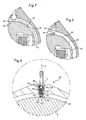
- the surface forming cam 20 has a plurality of notches 45 distributed for example regularly around of the X axis, as shown in Figures 7 and 8.
- These notches 45 may be configured to correspond to angular positions for indexing the rotor 4 in the body 2.
- the elastic return member when the elastic return member is constituted by a leaf spring 26, the latter may comprise a projecting portion 30 able to engage in notches 45.
- the elastic return member comprises a support element 42 fixed on a helical spring 41
- the support element 42 can be arranged to engage in a notch 45 of the rotor 4.
- a camming surface that extends only on an angular sector less than 360 °, and for example on an angular sector of about 180 °.
Landscapes
- Health & Medical Sciences (AREA)
- Engineering & Computer Science (AREA)
- Biomedical Technology (AREA)
- Hematology (AREA)
- Animal Behavior & Ethology (AREA)
- Otolaryngology (AREA)
- Anesthesiology (AREA)
- Heart & Thoracic Surgery (AREA)
- Neurology (AREA)
- Life Sciences & Earth Sciences (AREA)
- Ophthalmology & Optometry (AREA)
- General Health & Medical Sciences (AREA)
- Public Health (AREA)
- Veterinary Medicine (AREA)
- Mechanically-Actuated Valves (AREA)
- Media Introduction/Drainage Providing Device (AREA)
- External Artificial Organs (AREA)
- Infusion, Injection, And Reservoir Apparatuses (AREA)
Abstract
Description
- un corps définissant une chambre et comportant un orifice d'entrée et un orifice de sortie débouchant dans la chambre,
- un obturateur apte à obturer au moins partiellement l'orifice d'entrée,
- un organe de rappel élastique agencé pour maintenir l'obturateur contre l'orifice d'entrée afin de réguler le passage de liquide par cet orifice d'entrée,
- un rotor logé dans la chambre,
- la figure 1 représente, schématiquement et partiellement, en coupe axiale, une valve sous-cutanée conforme à l'invention,
- la figure 2 est une vue schématique et partielle de deux micro-aimants destinés à équiper la valve de la figure 1,
- la figure 3 représente, schématiquement et partiellement, en coupe axiale, le rotor de la valve de la figure 1,
- la figure 4 représente, schématiquement et partiellement, en coupe axiale, une valve selon un autre exemple de mise en oeuvre de l'invention, et
- les figures 5 à 9 illustrent, schématiquement et partiellement, d'autres variantes de mise en oeuvre de l'invention.
Claims (15)
- Valve sous-cutanée (1 ; 40) comportant :la valve étant caractérisée par le fait que le rotor (4) comporte une surface formant came (20) et par le fait que l'organe de rappel élastique (26 ; 41, 42 ; 51) vient en appui sur ladite surface du rotor en formant un contact mobile avec ladite surface.un corps (2) définissant une chambre (3) et comportant un orifice d'entrée (5) et un orifice de sortie (6) débouchant dans la chambre (3),un obturateur (23) apte à obturer au moins partiellement l'orifice d'entrée (5),un organe de rappel élastique (26 ; 41, 42 ; 51) agencé pour maintenir l'obturateur (23) contre l'orifice d'entrée afin de réguler le passage de liquide par cet orifice d'entrée,un rotor (4) logé dans la chambre,
- Valve selon la revendication 1, caractérisée par le fait que l'organe de rappel élastique (26) est fixé, notamment à une extrémité, sur le corps de la valve.
- Valve selon l'une des revendications précédentes, caractérisée par le fait que l'organe de rappel élastique comporte un ressort à lame (26), notamment un ressort à lame courbe.
- Valve selon la revendication 3, caractérisée par le fait que le ressort à lame comporte une portion en saillie (30) venant en appui sur la surface formant came (20).
- Valve selon la revendication 3, caractérisée par le fait que l'organe de rappel élastique comporte un élément d'appui (36) fixé sur le ressort à lame (26') et apte à glisser sur la surface formant came.
- Valve selon l'une quelconque des revendications 3 à 4, caractérisée par le fait que l'organe de rappel élastique comporte un unique ressort à lame (26).
- Valve selon l'une quelconque des revendications 3 à 4, caractérisée par le fait que l'organe de rappel élastique comporte au moins deux ressorts à lame (26 ; 35) assemblés.
- Valve selon la revendication 1, caractérisée par le fait que l'organe de rappel élastique (41) est indépendant du corps de la valve.
- Valve selon la revendication 8, caractérisée par le fait que l'organe de rappel élastique comporte un ressort, notamment hélicoïdal (41 ; 51), lequel est notamment solidaire à une extrémité d'un élément d'appui (42) apte à glisser sur la surface formant came, l'autre extrémité du ressort étant notamment en appui sur l'obturateur.
- Valve selon la revendication 9, caractérisée par le fait qu'un ressort additionnel (59) est disposé entre, d'une part, l'élément d'appui (53) et, d'autre part, le corps de la valve ou un insert fixé sur ce corps.
- Valve selon l'une quelconque des revendications précédentes, caractérisée par le fait que la surface formant came s'étend sur tout le pourtour du rotor.
- Valve selon l'une quelconque des revendications précédentes, caractérisée par le fait que la surface formant came présente un rayon croissant sur un secteur angulaire supérieur à 180°, notamment sensiblement égal à 360°.
- Valve selon l'une quelconque des revendications précédentes, caractérisée par le fait que la surface formant came comporte au moins un renfoncement (45), notamment une pluralité de renfoncements répartis tout autour de l'axe de rotation du rotor, dans lequel ou lesquels peut s'engager une portion de l'organe de rappel élastique.
- Valve selon l'une quelconque des revendications précédentes, caractérisée par le fait que l'obturateur comporte une bille (23).
- Valve selon l'une quelconque des revendications précédentes, caractérisée par le fait que le rotor comporte deux micro-aimants (12 ; 13) mobiles linéairement par rapport au rotor (40) suivant une direction sensiblement radiale et aptes à coopérer avec des moyens de verrouillage (18) du rotor dans une position angulaire prédéterminée.
Applications Claiming Priority (2)
| Application Number | Priority Date | Filing Date | Title |
|---|---|---|---|
| FR0451264 | 2004-06-11 | ||
| FR0451264A FR2871386B1 (fr) | 2004-06-11 | 2004-06-11 | Valve sous-cutanee |
Publications (2)
| Publication Number | Publication Date |
|---|---|
| EP1604703A1 true EP1604703A1 (fr) | 2005-12-14 |
| EP1604703B1 EP1604703B1 (fr) | 2011-08-24 |
Family
ID=34946059
Family Applications (1)
| Application Number | Title | Priority Date | Filing Date |
|---|---|---|---|
| EP05300461A Expired - Lifetime EP1604703B1 (fr) | 2004-06-11 | 2005-06-07 | Valve sous-cutanée |
Country Status (5)
| Country | Link |
|---|---|
| US (1) | US7758536B2 (fr) |
| EP (1) | EP1604703B1 (fr) |
| JP (1) | JP4979899B2 (fr) |
| ES (1) | ES2372181T3 (fr) |
| FR (1) | FR2871386B1 (fr) |
Cited By (7)
| Publication number | Priority date | Publication date | Assignee | Title |
|---|---|---|---|---|
| EP2420284A3 (fr) * | 2010-08-17 | 2012-04-25 | Codman & Shurtleff, Inc. | Valvule réglable implantable |
| WO2015036976A1 (fr) | 2013-09-16 | 2015-03-19 | Sophysa | Valve de drainage ajustable |
| US9149615B2 (en) | 2010-08-17 | 2015-10-06 | DePuy Synthes Products, Inc. | Method and tools for implanted device |
| US9572965B2 (en) | 2012-09-11 | 2017-02-21 | C.Miethke Gmbh & Co Kg | Adjustable hydrocephalus valve |
| WO2019040841A1 (fr) * | 2017-08-24 | 2019-02-28 | Medtronic Xomed, Inc. | Procédé et appareil d'ajustement de soupape |
| US10569065B2 (en) | 2012-09-11 | 2020-02-25 | Christoph Miethke Gmbh & Co Kg | Adjustable hydrocephalus valve |
| US20200282200A1 (en) * | 2016-08-12 | 2020-09-10 | Carlos A. Hakim | Externally programable magnetic valve assembly and controller |
Families Citing this family (8)
| Publication number | Priority date | Publication date | Assignee | Title |
|---|---|---|---|---|
| US8038641B2 (en) * | 2009-03-31 | 2011-10-18 | Codman & Shurtleff, Inc. | Tools and methods for programming an implantable valve |
| US8591499B2 (en) * | 2009-10-30 | 2013-11-26 | Medos International S.A.R.L. | Tools and methods for programming an implantable valve |
| US8241240B2 (en) | 2009-11-09 | 2012-08-14 | Medtronic Xomed, Inc. | Adjustable valve setting with motor control |
| CN103574090B (zh) * | 2012-08-10 | 2016-07-20 | 浙江金氟隆化工装备有限公司 | 一种新型阀门 |
| CN103090100A (zh) * | 2012-12-03 | 2013-05-08 | 柳州柳工叉车有限公司 | 带自锁功能的多路阀 |
| CA2855315C (fr) * | 2013-06-28 | 2021-08-10 | DePuy Synthes Products, LLC | Methode et outil de dispositif implante |
| AR116360A1 (es) * | 2018-09-06 | 2021-04-28 | Hp Bioproteses Ltda | Válvula programable para el tratamiento de la hidrocefalia |
| CN119491849B (zh) * | 2025-01-17 | 2025-05-02 | 杭州鑫高科技有限公司 | 一种伺服电机直驱型比例伺服阀 |
Citations (5)
| Publication number | Priority date | Publication date | Assignee | Title |
|---|---|---|---|---|
| US4673384A (en) | 1986-04-14 | 1987-06-16 | Sophysa | Valve for the treatment of hydrocephalus |
| EP0688575A1 (fr) * | 1994-06-24 | 1995-12-27 | SOPHYSA Société Anonyme | Valve sous-cutanée et son dispositif de réglage externe |
| US5637083A (en) * | 1996-01-19 | 1997-06-10 | Pudenz-Schulte Medical Research Corporation | Implantable adjustable fluid flow control valve |
| FR2804331A1 (fr) * | 2000-02-02 | 2001-08-03 | Nmt Neurosciences Implants | Valve pour le traitement de l'hydrocephalie |
| EP1205210A1 (fr) * | 2000-11-13 | 2002-05-15 | Bernard Marion | Valve sous-cutanée pour le traitement de l'hydrocéphalie et ses dispositifs de réglage |
Family Cites Families (10)
| Publication number | Priority date | Publication date | Assignee | Title |
|---|---|---|---|---|
| FR2502012A1 (fr) * | 1981-03-18 | 1982-09-24 | Sophysa Sa | Valve pour le traitement de l'hydrocephalie |
| US4615691A (en) * | 1983-12-08 | 1986-10-07 | Salomon Hakim | Surgically-implantable stepping motor |
| US4772257A (en) * | 1983-12-08 | 1988-09-20 | Salomon Hakim | External programmer for magnetically-adjustable cerebrospinal fluid shunt valve |
| US4857061A (en) * | 1988-04-15 | 1989-08-15 | Miller Michael D | Single-flow valve-hypodermic needle combination |
| JP3852734B2 (ja) * | 1999-12-20 | 2006-12-06 | セイコーインスツル株式会社 | 圧力可変弁装置及び該弁装置の設定圧力調整装置 |
| JP2002022048A (ja) * | 2000-07-06 | 2002-01-23 | Seiko Instruments Inc | 圧力可変弁装置 |
| ES2461625T3 (es) * | 2002-02-25 | 2014-05-20 | Sequana Medical Ag | Derivación vesical para el drenaje de exceso de fluido |
| US7390310B2 (en) * | 2002-07-10 | 2008-06-24 | Codman & Shurtleff, Inc. | Shunt valve locking mechanism |
| JP4594862B2 (ja) | 2002-12-11 | 2010-12-08 | クリストフ ミートケ ゲゼルシャフト ミット ベシュレンクテル ハフツング ウント コンパニー コマンディトゲゼルシャフト | 調節式水頭症バルブ |
| DK1613388T3 (da) | 2004-03-27 | 2008-03-25 | Christoph Miethke Gmbh & Co Kg | Indstillelig hydrocephalus-ventil |
-
2004
- 2004-06-11 FR FR0451264A patent/FR2871386B1/fr not_active Expired - Lifetime
-
2005
- 2005-06-03 US US11/143,634 patent/US7758536B2/en active Active
- 2005-06-07 EP EP05300461A patent/EP1604703B1/fr not_active Expired - Lifetime
- 2005-06-07 ES ES05300461T patent/ES2372181T3/es not_active Expired - Lifetime
- 2005-06-10 JP JP2005170941A patent/JP4979899B2/ja not_active Expired - Fee Related
Patent Citations (6)
| Publication number | Priority date | Publication date | Assignee | Title |
|---|---|---|---|---|
| US4673384A (en) | 1986-04-14 | 1987-06-16 | Sophysa | Valve for the treatment of hydrocephalus |
| EP0688575A1 (fr) * | 1994-06-24 | 1995-12-27 | SOPHYSA Société Anonyme | Valve sous-cutanée et son dispositif de réglage externe |
| EP0688575B1 (fr) | 1994-06-24 | 1999-09-22 | SOPHYSA Société Anonyme | Valve sous-cutanée et son dispositif de réglage externe |
| US5637083A (en) * | 1996-01-19 | 1997-06-10 | Pudenz-Schulte Medical Research Corporation | Implantable adjustable fluid flow control valve |
| FR2804331A1 (fr) * | 2000-02-02 | 2001-08-03 | Nmt Neurosciences Implants | Valve pour le traitement de l'hydrocephalie |
| EP1205210A1 (fr) * | 2000-11-13 | 2002-05-15 | Bernard Marion | Valve sous-cutanée pour le traitement de l'hydrocéphalie et ses dispositifs de réglage |
Cited By (16)
| Publication number | Priority date | Publication date | Assignee | Title |
|---|---|---|---|---|
| US8322365B2 (en) | 2010-08-17 | 2012-12-04 | Codman & Shurtleff, Inc. | Implantable adjustable valve |
| US8617142B2 (en) | 2010-08-17 | 2013-12-31 | DePuy Synthes Products, LLC | Implantable adjustable valve |
| US9149615B2 (en) | 2010-08-17 | 2015-10-06 | DePuy Synthes Products, Inc. | Method and tools for implanted device |
| AU2016203496B2 (en) * | 2010-08-17 | 2017-11-16 | Integra LifeSciences Switzerland Sarl | Implantable adjustable valve |
| US10092734B2 (en) | 2010-08-17 | 2018-10-09 | Integra LifeSciences Switzerland Sarl | Method and tools for implanted device |
| EP2420284A3 (fr) * | 2010-08-17 | 2012-04-25 | Codman & Shurtleff, Inc. | Valvule réglable implantable |
| US10569065B2 (en) | 2012-09-11 | 2020-02-25 | Christoph Miethke Gmbh & Co Kg | Adjustable hydrocephalus valve |
| US9572965B2 (en) | 2012-09-11 | 2017-02-21 | C.Miethke Gmbh & Co Kg | Adjustable hydrocephalus valve |
| WO2015036976A1 (fr) | 2013-09-16 | 2015-03-19 | Sophysa | Valve de drainage ajustable |
| US10357639B2 (en) | 2013-09-16 | 2019-07-23 | Sophysa | Adjustable drainage valve |
| US20200282200A1 (en) * | 2016-08-12 | 2020-09-10 | Carlos A. Hakim | Externally programable magnetic valve assembly and controller |
| US12420075B2 (en) * | 2016-08-12 | 2025-09-23 | Ceredyn Biotechnology Llc | Externally programable magnetic valve assembly and controller |
| CN111032143A (zh) * | 2017-08-24 | 2020-04-17 | 美敦力施美德公司 | 用于阀调节的方法和装置 |
| WO2019040841A1 (fr) * | 2017-08-24 | 2019-02-28 | Medtronic Xomed, Inc. | Procédé et appareil d'ajustement de soupape |
| US10799689B2 (en) | 2017-08-24 | 2020-10-13 | Medtronic Xomed, Inc. | Method and apparatus for valve adjustment |
| US12017024B2 (en) | 2017-08-24 | 2024-06-25 | Medtronic Xomed, Inc. | Method and apparatus for valve adjustment |
Also Published As
| Publication number | Publication date |
|---|---|
| EP1604703B1 (fr) | 2011-08-24 |
| FR2871386A1 (fr) | 2005-12-16 |
| JP4979899B2 (ja) | 2012-07-18 |
| ES2372181T3 (es) | 2012-01-16 |
| FR2871386B1 (fr) | 2006-09-22 |
| US20050279960A1 (en) | 2005-12-22 |
| US7758536B2 (en) | 2010-07-20 |
| JP2005349209A (ja) | 2005-12-22 |
Similar Documents
| Publication | Publication Date | Title |
|---|---|---|
| EP1604703B1 (fr) | Valve sous-cutanée | |
| EP1388699A1 (fr) | Dispositif de maintien de tuyauteries | |
| EP1450883A1 (fr) | Dispositif de controle de debit, a usage medical | |
| EP0051022A1 (fr) | Charnière de lunettes | |
| FR3026353A1 (fr) | Aerateur et vehicule comprenant un tel aerateur | |
| CA2666557A1 (fr) | Instrument d'ecriture sans capuchon | |
| EP1205210A1 (fr) | Valve sous-cutanée pour le traitement de l'hydrocéphalie et ses dispositifs de réglage | |
| EP2795025A1 (fr) | Clé à insert escamotable et module de déploiement correspondant | |
| EP2349738B1 (fr) | Instrument d'écriture à pointe rétractable | |
| FR2943413A1 (fr) | Dispositif de transmission pour un capteur de position d'une boite de commande de turbocompresseur | |
| EP3245983A1 (fr) | Valve pour emboîture de prothèse | |
| FR2915873A1 (fr) | Dispositif de bras articule porte-outil destine a porter un instrument chirurgical. | |
| EP2244954A1 (fr) | Bouchon anti-goutte comportant un moyen elastique integre a une soupape | |
| EP0611219B1 (fr) | Soupapes de sûreté à membrane du type cartouche, de conception modulaire | |
| FR2847206A1 (fr) | Dispositif permettant de commander l'ecoulement d'un fluide et d'orienter cet ecoulement dans une direction determinee | |
| FR2906586A1 (fr) | Embout de fixation universel et ensemble de fixation comprenant un tel embout | |
| FR2791114A1 (fr) | Dispositif permettant de commander l'ecoulement d'un fluide et l'orientation de cet ecoulement | |
| EP3413863B1 (fr) | Article de puériculture, embout spécialement adapté pour un tel article de puériculture et procédé d'assemblage d'un tel article de puériculture | |
| FR2461347A1 (fr) | Dispositif index pour commutateur rotatif | |
| FR2739087A1 (fr) | Dispositif de conditionnement et de distribution a debit reglable | |
| FR2910088A1 (fr) | Mecanisme d'articulation | |
| FR2683289A1 (fr) | Joint pour vanne a papillon et vanne a papillon pourvue d'un tel joint. | |
| WO2025074064A1 (fr) | Agencement avec vanne double sens pour la ventilation d'un boîtier de batterie(s) et procede d'assemblage | |
| FR3082405A1 (fr) | Conditionnement exterieur reutilisable et etui cosmetique comprenant un tel conditionnement | |
| FR3052223A1 (fr) | Soupape de surpression et vanne de distribution de fluide comprenant une telle soupape |
Legal Events
| Date | Code | Title | Description |
|---|---|---|---|
| PUAI | Public reference made under article 153(3) epc to a published international application that has entered the european phase |
Free format text: ORIGINAL CODE: 0009012 |
|
| AK | Designated contracting states |
Kind code of ref document: A1 Designated state(s): AT BE BG CH CY CZ DE DK EE ES FI FR GB GR HU IE IS IT LI LT LU MC NL PL PT RO SE SI SK TR |
|
| AX | Request for extension of the european patent |
Extension state: AL BA HR LV MK YU |
|
| 17P | Request for examination filed |
Effective date: 20060502 |
|
| AKX | Designation fees paid |
Designated state(s): BE CH DE ES GB IT LI |
|
| 17Q | First examination report despatched |
Effective date: 20071107 |
|
| GRAP | Despatch of communication of intention to grant a patent |
Free format text: ORIGINAL CODE: EPIDOSNIGR1 |
|
| GRAC | Information related to communication of intention to grant a patent modified |
Free format text: ORIGINAL CODE: EPIDOSCIGR1 |
|
| GRAS | Grant fee paid |
Free format text: ORIGINAL CODE: EPIDOSNIGR3 |
|
| GRAA | (expected) grant |
Free format text: ORIGINAL CODE: 0009210 |
|
| AK | Designated contracting states |
Kind code of ref document: B1 Designated state(s): BE CH DE ES GB IT LI |
|
| REG | Reference to a national code |
Ref country code: GB Ref legal event code: FG4D Free format text: NOT ENGLISH |
|
| REG | Reference to a national code |
Ref country code: CH Ref legal event code: EP |
|
| REG | Reference to a national code |
Ref country code: DE Ref legal event code: R096 Ref document number: 602005029699 Country of ref document: DE Effective date: 20111020 |
|
| REG | Reference to a national code |
Ref country code: CH Ref legal event code: NV Representative=s name: KIRKER & CIE S.A. |
|
| REG | Reference to a national code |
Ref country code: ES Ref legal event code: FG2A Ref document number: 2372181 Country of ref document: ES Kind code of ref document: T3 Effective date: 20120116 |
|
| PLBE | No opposition filed within time limit |
Free format text: ORIGINAL CODE: 0009261 |
|
| STAA | Information on the status of an ep patent application or granted ep patent |
Free format text: STATUS: NO OPPOSITION FILED WITHIN TIME LIMIT |
|
| 26N | No opposition filed |
Effective date: 20120525 |
|
| REG | Reference to a national code |
Ref country code: DE Ref legal event code: R097 Ref document number: 602005029699 Country of ref document: DE Effective date: 20120525 |
|
| PGFP | Annual fee paid to national office [announced via postgrant information from national office to epo] |
Ref country code: IT Payment date: 20230523 Year of fee payment: 19 Ref country code: DE Payment date: 20230523 Year of fee payment: 19 |
|
| PGFP | Annual fee paid to national office [announced via postgrant information from national office to epo] |
Ref country code: BE Payment date: 20230523 Year of fee payment: 19 |
|
| PGFP | Annual fee paid to national office [announced via postgrant information from national office to epo] |
Ref country code: GB Payment date: 20230523 Year of fee payment: 19 Ref country code: ES Payment date: 20230703 Year of fee payment: 19 Ref country code: CH Payment date: 20230702 Year of fee payment: 19 |
|
| REG | Reference to a national code |
Ref country code: DE Ref legal event code: R119 Ref document number: 602005029699 Country of ref document: DE |
|
| REG | Reference to a national code |
Ref country code: CH Ref legal event code: PL |
|
| GBPC | Gb: european patent ceased through non-payment of renewal fee |
Effective date: 20240607 |
|
| PG25 | Lapsed in a contracting state [announced via postgrant information from national office to epo] |
Ref country code: DE Free format text: LAPSE BECAUSE OF NON-PAYMENT OF DUE FEES Effective date: 20250101 |
|
| PG25 | Lapsed in a contracting state [announced via postgrant information from national office to epo] |
Ref country code: CH Free format text: LAPSE BECAUSE OF NON-PAYMENT OF DUE FEES Effective date: 20240630 Ref country code: BE Free format text: LAPSE BECAUSE OF NON-PAYMENT OF DUE FEES Effective date: 20240630 |
|
| PG25 | Lapsed in a contracting state [announced via postgrant information from national office to epo] |
Ref country code: GB Free format text: LAPSE BECAUSE OF NON-PAYMENT OF DUE FEES Effective date: 20240607 Ref country code: IT Free format text: LAPSE BECAUSE OF NON-PAYMENT OF DUE FEES Effective date: 20240607 |
|
| REG | Reference to a national code |
Ref country code: BE Ref legal event code: MM Effective date: 20240630 |
|
| REG | Reference to a national code |
Ref country code: ES Ref legal event code: FD2A Effective date: 20250728 |
|
| PG25 | Lapsed in a contracting state [announced via postgrant information from national office to epo] |
Ref country code: ES Free format text: LAPSE BECAUSE OF NON-PAYMENT OF DUE FEES Effective date: 20240608 |