EP1605148A1 - Procédé et système de protection des injecteurs de carburant de turbine à gaz - Google Patents
Procédé et système de protection des injecteurs de carburant de turbine à gaz Download PDFInfo
- Publication number
- EP1605148A1 EP1605148A1 EP05291099A EP05291099A EP1605148A1 EP 1605148 A1 EP1605148 A1 EP 1605148A1 EP 05291099 A EP05291099 A EP 05291099A EP 05291099 A EP05291099 A EP 05291099A EP 1605148 A1 EP1605148 A1 EP 1605148A1
- Authority
- EP
- European Patent Office
- Prior art keywords
- fuel
- injectors
- air
- injection
- injector
- Prior art date
- Legal status (The legal status is an assumption and is not a legal conclusion. Google has not performed a legal analysis and makes no representation as to the accuracy of the status listed.)
- Granted
Links
Images


Classifications
-
- F—MECHANICAL ENGINEERING; LIGHTING; HEATING; WEAPONS; BLASTING
- F02—COMBUSTION ENGINES; HOT-GAS OR COMBUSTION-PRODUCT ENGINE PLANTS
- F02C—GAS-TURBINE PLANTS; AIR INTAKES FOR JET-PROPULSION PLANTS; CONTROLLING FUEL SUPPLY IN AIR-BREATHING JET-PROPULSION PLANTS
- F02C7/00—Features, components parts, details or accessories, not provided for in, or of interest apart form groups F02C1/00 - F02C6/00; Air intakes for jet-propulsion plants
- F02C7/22—Fuel supply systems
- F02C7/232—Fuel valves; Draining valves or systems
-
- F—MECHANICAL ENGINEERING; LIGHTING; HEATING; WEAPONS; BLASTING
- F05—INDEXING SCHEMES RELATING TO ENGINES OR PUMPS IN VARIOUS SUBCLASSES OF CLASSES F01-F04
- F05D—INDEXING SCHEME FOR ASPECTS RELATING TO NON-POSITIVE-DISPLACEMENT MACHINES OR ENGINES, GAS-TURBINES OR JET-PROPULSION PLANTS
- F05D2260/00—Function
- F05D2260/60—Fluid transfer
- F05D2260/602—Drainage
Definitions
- the invention relates to a method and a protection system fuel injectors in turbomachines and more precisely turbojets.
- turbojet fuel injectors are very sensitive to fuel degradation by temperature. This phenomenon, called coking, occurs when the fuel temperature exceeds a critical threshold of approximately 204 ° C. This temperature comes from the flame of the room of combustion in which the injectors are located plunged. Injectors are very sensitive to this phenomenon in because of fuel flow disturbances and even obstruction, that it leads.
- coking can cause an impossibility to start a motor on the ground, a impossibility to restart a motor in flight, perforation of the combustion chamber, or the destruction of the turbine blades.
- the critical phases with respect to the coking are different according to the type of injector used.
- the critical phase is the stopping of the engine. Indeed, the radiation and the temperature of the turbojet engine remain very high for a long time after stopping the engine, while the injectors no longer deliver fuel and no longer exhaust the calories.
- the tendency is to decrease in the size of the injected fuel drops and the use of multipoint type injectors.
- the multipoint injectors are equipped with several fuel outlets, the diameters of these openings being able to on the same injector, be different.
- the increase in number of injection points makes it possible to homogenise the spraying throughout the space formed by the combustion chamber.
- the amount of fuel injected is identical to the quantity injected in the case of the use injectors with a single exit port, which implies that the outlets of the injectors multipoints have smaller diameters.
- the multipoint injectors can be used in single or double head rooms.
- Purge is a method of protecting injectors from fuel well known and widely used, especially on turbojets.
- the entire injection boom of fuel is purged at the same time as the injectors by injection of compressed air, the air being stored, cooled and possibly re-compressed.
- the non-return valve preventing any backflow of purge air into the fuel supply system, is located upstream of the fuel supply ramp. This imposes, during the bleed, empty the fuel injection ramp and the injectors, thus releasing into the combustion chamber a large amount of fuel, which may ignite.
- it is then necessary to refill these injection ramps fuel hence a long time to achieve it.
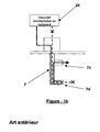
- the method of protecting fuel injectors by cooling is used in particular in the case of double-headed combustion chambers as shown in the Figure 1a.
- This method involves circulating the fuel inside the injectors at rest 7a before send it to the operational injectors 7b by which it will be ejected into the combustion chamber.
- This method is also applied with injectors called "double-heads" As shown in Figure 1b.
- the fuel circulates in the head 7d that does not charge for the cool before being ejected into the room by the second injector head 7c.
- a first disadvantage of this system of Prevention of coking is linked to the complexity of cooling circuit to put in place.
- a second disadvantage is related to the fact that the cooling did not only during engine operation. Indeed, as soon as the engine is stopped, the fuel circulation used to cool injectors is stopped, and all injectors is then subjected to engine radiation, so at the risk of coking.
- the object of the invention is to overcome the disadvantages of existing protection systems by defining a process and a fuel injector protection system, which can replace the purge protection systems and existing cooling systems and that can be applied to all types of injectors and for all combustion chambers, whether they are single or double-headed.
- the protection method of fuel injectors of a turbomachine consists, during operating phases where the power supply fuel from at least one injection head is stopped, at injecting compressed air into a fuel supply system fuel injectors, the air being injected directly and only in each fuel injection head not supplied, downstream of a non-return valve dedicated to each injection head and disposed on each fuel line internal to the injectors.
- the injection of compressed air into the heads non-fueled injection is driven by control means, from an input signal representative of the operating regime of the turbomachine.
- the compressed air is taken out of a compressor of the turbomachine and then stored in a tank.
- the stored compressed air is then injected directly into each fuel injection head no fueled via a fuel line internal to the corresponding non-powered injector.
- the invention also relates to a protection system for fuel injectors of a turbomachine comprising fuel injectors having at least one injection head of fuel, a compressed air sampling line connected to an inlet of an air tank via a first check valve, the air tank having a system cooling and an output connected to a pipe of air injection via an air injection ramp and a second non-return valve implanted so as to open in the direction of the air injection, the air injection line being intended to be directly and only connected to at least one non-powered fuel injection head and a non-return valve being arranged on each pipe of fuel internal injectors.
- the non-return valves arranged on each internal fuel pipe are positioned inside of each fuel injector.
- the system further includes an air outlet valve compressed from the tank to the air injection ramp controlled by a calculator, the outlet valve leaving Pass air under pressure only in the heads non-fueled injection.
- the device comprises means for regulating the purge air flow such as, for example, a diaphragm.
- the means for regulating the air flow of purge comprise a servovalve, controlled by the computer, arranged downstream of the tank.
- the compressed air withdrawal pipe is intended to be connected at the output of a compressor of the turbine engine.
- the present invention also relates to a turbomachine having at least one compressor and at least one injector of fuel, the injector comprising at least one head of fuel injection equipped with a pipe fuel supply system, comprising a fuel protection of the connected injector between an output of compressor and a fuel supply line.
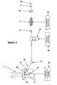
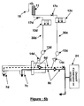
- FIG. 2 represents a diagrammatic sectional view of an example of a turbojet engine 1 equipped with an example of a fuel injector protection device 22 .
- the turbojet engine essentially comprises a low-pressure compressor 2 equipped with a fan 3, a high-pressure compressor 4, a combustion chamber 5 and a turbine 6.
- the fuel is fed to the fuel injectors 7 via pipes 8, connected to a fuel supply device 24 by a fuel supply ramp (not shown). The fuel is then ejected into the chamber 5.
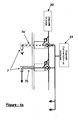
- the device for protecting the fuel injectors also called bleeding device, shown in FIGS. 2 and 3, essentially comprises an air sampling line 9, a first non-return valve 10, a strongly compressed air tank 11 being able to be equipped with cooling fins, a purge control valve 12, an air injection ramp 13, a second non-return valve 14 and an air injection duct 15.
- Injector 7 has an internal fuel line 8 on which is connected a non-return valve 16. This valve Maybe inside the injector or outside of the injector but still downstream of the feed ramp in fuel.
- the purge device is connected between an outlet 18 of the compressor 4 of the turbojet engine and a pipe 23 connected to an inlet 19 of a fuel injector 7.
- the compressed air is taken at the outlet of the high-pressure compressor 4, via the sampling line 9, and is accumulated in the tank 11.
- the tank 11 is equipped with a non-return valve 10 avoiding its discharge. in the compressor 4. Since the air can be at high temperature at the outlet of the compressor 4, the reservoir is advantageously equipped with cooling means 21 such as, for example, an air / air heat exchanger whose cold source comes for example from the air flow rate. the air delivered by the fan 3. This heat exchange can be performed for example by installing cooling fins on the tank 11.
- the non-return valve 14 prevents any ascent of fuel in the air injection manifold 13.
- This valve 14 can be located in the injector 7, as shown in Figure 2, or on the air injection manifold 13, as shown in the following figures which we will detail later.
- the purge control valve 12 controlled by control means 20 such as, for example, a calculator, opens and the underpressure air leaves the tank 11.
- the input signal of these control means may be, for example, the pressure level reached at the outlet of the compressor, or the rotational speed of the turbojet engine.
- the pressure upstream of the valve 14 becomes greater than the pressure downstream.
- the valve 14 then opens and releases the compressed air into the air injection pipe 15, connected to the injector via the pipe 23. The compressed air thus released will purge the injector 7 by evacuating the fuel located in the chamber 5.
- the valve 16 may be located in the injector 7 or on the fuel supply ramp.
- the diaphragm 17 can be replaced by a servovalve, controlled by the computer 20. It allows to dose the purge air flow to limit the flow of fuel injected into the chamber 5. This avoids the appearance of hot spots from the ignition of the purged fuel, in the vicinity of the turbine 6. It thus ensures the viability of the purge system over a wide range of operation while preserving the mechanical integrity of the combustion chamber 5 and modules downstream.
- the flow rate is determined according to the available pressure in the tank and the pressure in the combustion chamber 5.
- the purge device can be connected to a fuel injector as described in connection with Figure 2, but it can also be connected to several injectors or injection heads.
- the air injection ramp 13 is connected to each of the injectors or fuel injection heads via non-return valves 14 and air injection pipes 15. This ramp is intended to distribute the air homogeneously and simultaneously to all injectors or injection heads when they are no longer fueled. There is then a non-return valve 16 by injector or injection head.
- Figures 4a and 4b show the application of the invention in the case of a "double-head" combustion chamber in which the injectors are not all supplied with fuel at the same time, ie in the case where the injectors do not all work at the same time.
- FIGS are represented two injectors 7a and 7b.
- the injector 7a is not powered and therefore does not deliver fuel.
- the injector 7b is fed and injects fuel into the combustion chamber.
- FIGS 5a and 5b show the application of the invention in the case of injectors called “dual heads" 7 for which only one of the two heads is supplied with fuel.
- These figures show an injector 7 provided with two internal fuel supply lines, each pipe leading to a first head 7c, respectively a second head 7d, of fuel injection.
- the head 7c is fed and injects fuel into the combustion chamber.
- the 7d head is not powered and therefore does not deliver fuel.
- FIGS. 4a and 5a illustrate the case where it is desired to purge the injectors, respectively the injection heads, which are not powered solely during the stopping of the turbomachine.
- the set of injectors 7a and 7b, respectively injection heads 7c and 7d is connected to a single purge device, whose operation is identical to that described above, in connection with FIG.
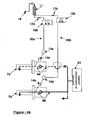
- FIGS. 4b and 5b illustrate the case where it is desired to purge the injectors, respectively the injection heads, which are not powered when stationary and during operation of the turbomachine.
- two purge circuits 30a and 30b, respectively 30c and 30d are put in place.
- the index "i" can take the values a, b, c or d according to the purge circuit considered.
- each purge circuit comprises a throttle 17i, a purge control valve 12i and an air injection manifold 13i.
- each purge circuit may have its own reservoir.
- the first of the two circuits 30a, respectively 30d is connected to all the injectors 7a, respectively the injection heads 7d, that is to say to all the injectors, respectively the injection heads, which will have to be purged at the same time. time during operation and shutdown of the turbomachine.
- the second circuit, numbered 30b, respectively 30c is connected to all the injectors 7b, respectively the injection heads 7c, ie to all the injectors which will be purged only at the shutdown of the turbomachine.
- the injectors 7a and 7b respectively the injection heads 7c and 7d, together deliver fuel into the combustion chamber 5.
- the injectors 7b respectively the injection heads 7c
- the injectors 7a respectively the injection heads 7d
- the purge control valve 12a respectively 12d, controlled by the control means 20, opens and the underpressure air exits the tank 11.
- the purge of the injectors and the injection heads is then carried out in accordance with the description made previously, in connection with FIG. 3.
- the two purge control valves 12a and 12b, respectively 12c and 12d open and the pressurized air comes to purge the set of injectors and injection heads.
- the invention is not limited to the embodiments precisely described. In particular, it applies also in the case of a single body turbomachine having a single compressor and a single turbine. In this In this case, air sampling is preferentially carried out compressor output. The air sampling could also be performed directly at the outlet of an external tank.
Landscapes
- Engineering & Computer Science (AREA)
- Chemical & Material Sciences (AREA)
- Combustion & Propulsion (AREA)
- Mechanical Engineering (AREA)
- General Engineering & Computer Science (AREA)
- Fuel-Injection Apparatus (AREA)
Abstract
Description
Dans le cas d'une chambre de combustion simple tête, c'est à dire avec une seule rangée circonférentielle d'injecteurs, tous les injecteurs fonctionnent en même temps, quel que soit le point de fonctionnement de la turbomachine considéré. Dans ce cas, la phase critique est l'arrêt du moteur. En effet, le rayonnement et la température du turboréacteur restent très élevés pendant une longue durée après l'arrêt du moteur, alors que les injecteurs ne débitent plus de carburant et n'évacuent plus les calories.
Dans le cas de chambres de combustion dites « double-têtes », c'est à dire avec deux rangées circonférentielles d'injecteurs de carburant, ou dans le cas de chambres de combustion comportant une seule rangée circonférentielle d'injecteurs dit « double-têtes », c'est à dire munis de deux têtes d'injection de carburant, les phases critiques sont l'arrêt du moteur, mais aussi les cas de fonctionnement avec une partie seulement des injecteurs, respectivement des têtes d'injection, qui sont opérationnels et qui débitent du carburant, les autres injecteurs, respectivement têtes d'injection, étant au repos. Par exemple, alors qu'au décollage toutes les têtes d'injection sont alimentées en carburant pour fournir le maximum de puissance, en croisière, le besoin en puissance, et donc l'apport en carburant, sont moindres et ne nécessitent le fonctionnement que d'une partie des injecteurs ou des têtes d'injection.
- figure la : une illustration du principe de refroidissement d'injecteurs de carburant dans le cas d'une chambre « double-tête » par circulation de carburant dans les injecteurs au repos, selon l'art antérieur,
- figure 1b: une illustration du principe de refroidissement d'injecteurs de carburant par circulation de carburant dans les injecteurs dans le cas d'injecteurs dits « double-tête », selon l'art antérieur,
- figure 2 : une vue schématique en coupe d'un turboréacteur équipé d'un système de protection des injecteurs de carburant conformément à l'invention.
- figure 3 : une représentation schématique détaillée d'un système de protection des injecteurs de carburant conformément à l'invention,
- figure 4a : une application de l'invention dans le cas d'une chambre « double-tête » fonctionnant avec une partie seulement des injecteurs débitant du carburant, pour laquelle la purge des injecteurs non alimentés n'est réalisée qu'à l'arrêt de la turbomachine,
- figure 4b : une application de l'invention dans le cas d'une chambre « double-tête » fonctionnant avec une partie seulement des injecteurs débitant du carburant, pour laquelle la purge des injecteurs non alimentés est réalisée à l'arrêt et pendant le fonctionnement de la turbomachine,
- figure 5a : une application de l'invention dans le cas d'injecteurs dits « double-tête », dont une tête seulement sur les deux que comprend chaque injecteur débite du carburant, et dont la purge des têtes d'injecteurs non alimentées n'est réalisée qu'à l'arrêt de la turbomachine,
- figure 5b : une application de l'invention dans le cas d'injecteurs dits « double-tête », dont une tête seulement sur les deux que comprend chaque injecteur débite du carburant, et dont la purge des têtes d'injecteurs non alimentées est réalisée à l'arrêt et pendant le fonctionnement de la turbomachine.
Dans un souci de clarté, la suite de la description adopte un système de numérotation avec indice. L'indice « i » peut prendre les valeurs a, b, c ou d selon le circuit de purge considéré.
En sortie d'un réservoir 11 d'air sous pression commun aux deux circuits sur les figures, chaque circuit de purge comporte, un étranglement 17i, une vanne de commande de purge 12i et une rampe d'injection d'air 13i. Alternativement, chaque circuit de purge peut comporter son propre réservoir. Le premier des deux circuits 30a, respectivement 30d, est relié à tous les injecteurs 7a, respectivement les têtes d'injection 7d, c'est à dire à tous les injecteurs, respectivement les têtes d'injection, qui vont devoir être purgés en même temps pendant le fonctionnement et à l'arrêt de la turbomachine. Le second circuit, numéroté 30b, respectivement 30c, est relié à tous les injecteurs 7b, respectivement les têtes d'injection 7c, c'est à dire à tous les injecteurs qui ne seront purgés qu'à l'arrêt de la turbomachine.
Claims (11)
- Procédé de protection d'injecteurs de carburant d'une turbomachine, les injecteurs comportant au moins une tête d'injection de carburant, consistant, pendant des phases de fonctionnement où l'alimentation en carburant d'au moins une tête d'injection est stoppée, à injecter de l'air comprimé dans un circuit d'alimentation des injecteurs en carburant,
caractérisé en ce que l'air comprimé est injecté directement et uniquement dans chaque tête d'injection de carburant (7) non alimentée en aval de clapets anti-retour (16) dédiés à chaque tête d'injection et disposés sur chaque conduite de carburant interne (8) aux injecteurs. - Procédé de protection d'injecteurs de carburant conformément à la revendication 1,
caractérisé en ce que l'injection d'air comprimé dans les têtes d'injection non alimentées en carburant est pilotée à partir d'un signal représentatif de la phase de fonctionnement de la turbomachine. - Procédé de protection d'injecteurs de carburant conformément à l'une quelconque des revendications 1 ou 2, caractérisé en ce que l'air comprimé est prélevé en sortie d'un compresseur de la turbomachine, puis stocké dans un réservoir (11), et en ce que l'air comprimé stocké est injecté directement dans chaque tête d'injection de carburant non alimentée par l'intermédiaire d'une conduite de carburant (8) interne à l'injecteur non alimenté correspondant.
- Système de protection des injecteurs de carburant d'une turbomachine comportant des injecteurs de carburant (7) ayant au moins une tête d'injection de carburant, une conduite (9) de prélèvement d'air comprimé reliée à une entrée d'un réservoir d'air (11) via un premier clapet anti-retour (10), le réservoir d'air (11) comportant un système de refroidissement (21) et une sortie reliée à une conduite d'injection d'air (15) via une rampe d'injection d'air (13) et un second clapet anti-retour (14)implanté de façon à s'ouvrir dans le sens de l'injection d'air,
caractérisé en ce que la conduite d'injection d'air (15) est directement et uniquement raccordée à au moins une tête d'injection de carburant (7) non alimentée et en ce qu'un clapet anti-retour (16) est disposé sur chaque conduite de carburant interne (8) aux injecteurs. - Système selon la revendication 4, caractérisé en ce que les clapets anti-retour (16) disposés sur chaque conduite de carburant interne (8) sont positionnés à l'intérieur de chaque injecteur de carburant (7).
- Système selon l'une quelconque des revendications 4 ou 5,
caractérisé en ce qu'il comporte en outre une vanne de sortie de l'air comprimé du réservoir (11) vers la rampe d'injection d'air (13) commandée par un calculateur, la vanne de sortie laissant passer l'air sous pression uniquement dans les têtes d'injection (7) non alimentées en carburant. - Système selon la revendication 6, caractérisé en ce qu'il comporte des moyens de régulation (17) du débit d'air de purge.
- Système selon la revendication 7, caractérisé en ce que les moyens de régulation (17) du débit d'air de purge comportent un diaphragme.
- Système selon la revendication 7, caractérisé en ce que les moyens de régulation (17) du débit d'air de purge comportent une servovalve commandée par le calculateur.
- Système selon l'une quelconque des revendications 4 à 9,
caractérisé en ce que la conduite (9) de prélèvement d'air comprimé est destinée à être reliée en sortie d'un compresseur (4) de la turbomachine. - Turbomachine comportant au moins un compresseur et au moins un injecteur de carburant, l'injecteur comportant au moins une tête d'injection de carburant équipée d'une conduite d'alimentation en carburant,
caractérisée en ce qu'elle comporte un système de protection de l'injecteur selon l'une quelconque des revendications 4 à 10, le système de protection étant relié entre une sortie du compresseur et une conduite d'alimentation en carburant.
Applications Claiming Priority (2)
| Application Number | Priority Date | Filing Date | Title |
|---|---|---|---|
| FR0406270A FR2871519B1 (fr) | 2004-06-10 | 2004-06-10 | Procede et systeme de protection des injecteurs de carburant de turbine de gaz |
| FR0406270 | 2004-06-10 |
Publications (2)
| Publication Number | Publication Date |
|---|---|
| EP1605148A1 true EP1605148A1 (fr) | 2005-12-14 |
| EP1605148B1 EP1605148B1 (fr) | 2015-02-18 |
Family
ID=34942330
Family Applications (1)
| Application Number | Title | Priority Date | Filing Date |
|---|---|---|---|
| EP05291099.9A Expired - Lifetime EP1605148B1 (fr) | 2004-06-10 | 2005-05-20 | Procédé et système de protection des injecteurs de carburant de turbine à gaz |
Country Status (4)
| Country | Link |
|---|---|
| US (1) | US7520136B2 (fr) |
| EP (1) | EP1605148B1 (fr) |
| FR (1) | FR2871519B1 (fr) |
| RU (1) | RU2296916C2 (fr) |
Cited By (4)
| Publication number | Priority date | Publication date | Assignee | Title |
|---|---|---|---|---|
| WO2015036703A1 (fr) * | 2013-09-13 | 2015-03-19 | Turbomeca | Procede de surveillance d'un degre de cokefaction au niveau de joints par un arbre de generateur de gaz |
| WO2015036694A1 (fr) * | 2013-09-13 | 2015-03-19 | Turbomeca | Surveillance d'un degre de cokefaction au niveau de joints dynamiques par le demarreur |
| WO2016055738A1 (fr) * | 2014-10-10 | 2016-04-14 | Turbomeca | Procédé et dispositif de notification d'une autorisation d'arrêt complet d'un moteur a turbine a gaz d'aéronef |
| FR3116082A1 (fr) | 2020-11-09 | 2022-05-13 | Safran Aircraft Engines | Turboréacteur à double flux pourvu de moyens de communication d’air |
Families Citing this family (17)
| Publication number | Priority date | Publication date | Assignee | Title |
|---|---|---|---|---|
| CN103109059B (zh) * | 2010-10-28 | 2015-09-09 | 三菱日立电力系统株式会社 | 燃气轮机及具有其的燃气轮机设备 |
| FR2996256B1 (fr) * | 2012-10-01 | 2018-06-15 | Safran Helicopter Engines | Dispositif d'alimentation et de purge pour injecteur. |
| WO2014130650A1 (fr) | 2013-02-20 | 2014-08-28 | United Technologies Corporation | Système d'injecteur de combustible à purge automatique pour turbine à gaz |
| US9915201B2 (en) * | 2013-03-04 | 2018-03-13 | Rolls-Royce Corporation | Aircraft power system |
| EP2975240B1 (fr) | 2014-07-18 | 2019-11-13 | United Technologies Corporation | Système de buse de combustible a purge automatique pour un moteur à turbine à gaz |
| US10393017B2 (en) | 2017-03-07 | 2019-08-27 | Rolls-Royce Corporation | System and method for reducing specific fuel consumption (SFC) in a turbine powered aircraft |
| GB2572783A (en) * | 2018-04-10 | 2019-10-16 | Rolls Royce Plc | A Gas Turbine Engine Comprising A Fuel Purging System And A Method of Purging Fuel From A Gas Turbine Engine |
| FR3086344A1 (fr) * | 2018-09-21 | 2020-03-27 | Ge Energy Products France Snc | Procede de determination du debit de gaz combustible injecte a l'interieur d'une turbine a gaz avec une ou plusieurs chambres de combustion sans diaphragme supplementaire |
| WO2020058617A1 (fr) * | 2018-09-21 | 2020-03-26 | Ge Energy Products France Snc | Procédé de détermination du débit de fluide combustible injecte à l'intérieur d'une chambre de combustion sans diaphragme supplementaire |
| US20200362760A1 (en) * | 2019-05-15 | 2020-11-19 | Pratt & Whitney Canada Corp. | System and method for purging a fuel manifold of a gas turbine engine using an accumulator |
| US11486303B2 (en) | 2019-05-15 | 2022-11-01 | Pratt & Whitney Canada Corp. | System and method for purging a fuel manifold of a gas turbine engine using a pump |
| US11536201B2 (en) | 2019-05-15 | 2022-12-27 | Pratt & Whitney Canada Corp. | System and method for purging a fuel manifold of a gas turbine engine through a flow divider valve |
| US11391214B2 (en) * | 2019-05-15 | 2022-07-19 | Pratt & Whitney Canada Corp. | System and method for purging a fuel manifold of a gas turbine engine using a flow divider assembly |
| US11047306B1 (en) | 2020-02-25 | 2021-06-29 | General Electric Company | Gas turbine engine reverse bleed for coking abatement |
| US11279225B2 (en) | 2020-04-07 | 2022-03-22 | General Atomics Aeronautical Systems, Inc. | Fault-tolerant fuel isolation from engine firebay |
| US11773776B2 (en) | 2020-05-01 | 2023-10-03 | General Electric Company | Fuel oxygen reduction unit for prescribed operating conditions |
| US11885287B2 (en) * | 2021-07-09 | 2024-01-30 | Rtx Corporation | De-preserving a fuel system of a turbine engine |
Citations (4)
| Publication number | Priority date | Publication date | Assignee | Title |
|---|---|---|---|---|
| US4730453A (en) * | 1985-10-23 | 1988-03-15 | Societe Nationale D'etude Et De Construction De Moteurs D'aviation "S.N.E.C.M.A." | Afterburner fuel injection system |
| DE3916477A1 (de) * | 1989-05-20 | 1990-11-22 | Mak Maschinenbau Krupp | Verfahren und einrichtung zum entleeren von kraftstoffleitungen und einspritzduesen in gasturbinen |
| US5881550A (en) * | 1995-08-18 | 1999-03-16 | Fuel Systems Textron, Inc. | Staged fuel injection system with shuttle valve and fuel injector therefor |
| US6125624A (en) * | 1998-04-17 | 2000-10-03 | Pratt & Whitney Canada Corp. | Anti-coking fuel injector purging device |
Family Cites Families (5)
| Publication number | Priority date | Publication date | Assignee | Title |
|---|---|---|---|---|
| US4242863A (en) * | 1978-03-16 | 1981-01-06 | Caterpillar Tractor Co. | Dual phase fuel vaporizing combustor |
| JPS60164627A (ja) * | 1984-02-06 | 1985-08-27 | Hitachi Ltd | 燃料ノズルパ−ジシステム装置 |
| SU1607970A1 (ru) * | 1988-07-11 | 1990-11-23 | Мариупольский металлургический институт | Форсунка |
| WO1999032770A1 (fr) * | 1997-12-20 | 1999-07-01 | Alliedsignal Inc. | Mise en memoire des pics de pression de l'air evacue du compresseur pour une purge prolongee des injecteurs de carburant d'un systeme de generation d'energie de microturbine |
| US5927253A (en) * | 1998-02-26 | 1999-07-27 | Ford Global Technologies, Inc. | Fuel system priming method |
-
2004
- 2004-06-10 FR FR0406270A patent/FR2871519B1/fr not_active Expired - Lifetime
-
2005
- 2005-05-20 EP EP05291099.9A patent/EP1605148B1/fr not_active Expired - Lifetime
- 2005-06-08 US US11/147,302 patent/US7520136B2/en active Active
- 2005-06-09 RU RU2005117880/06A patent/RU2296916C2/ru active
Patent Citations (4)
| Publication number | Priority date | Publication date | Assignee | Title |
|---|---|---|---|---|
| US4730453A (en) * | 1985-10-23 | 1988-03-15 | Societe Nationale D'etude Et De Construction De Moteurs D'aviation "S.N.E.C.M.A." | Afterburner fuel injection system |
| DE3916477A1 (de) * | 1989-05-20 | 1990-11-22 | Mak Maschinenbau Krupp | Verfahren und einrichtung zum entleeren von kraftstoffleitungen und einspritzduesen in gasturbinen |
| US5881550A (en) * | 1995-08-18 | 1999-03-16 | Fuel Systems Textron, Inc. | Staged fuel injection system with shuttle valve and fuel injector therefor |
| US6125624A (en) * | 1998-04-17 | 2000-10-03 | Pratt & Whitney Canada Corp. | Anti-coking fuel injector purging device |
Cited By (16)
| Publication number | Priority date | Publication date | Assignee | Title |
|---|---|---|---|---|
| RU2660989C2 (ru) * | 2013-09-13 | 2018-07-11 | Сафран Хеликоптер Энджинз | Контроль степени коксования на динамических уплотнениях посредством стартера |
| US9945246B2 (en) | 2013-09-13 | 2018-04-17 | Turbomeca | Monitoring of a degree of coking at dynamic seals by a starter |
| FR3010737A1 (fr) * | 2013-09-13 | 2015-03-20 | Turbomeca | Surveillance d'un degre de cokefaction au niveau de joints dynamiques par le demarreur |
| FR3010738A1 (fr) * | 2013-09-13 | 2015-03-20 | Turbomeca | Procede de surveillance d'un degre de cokefaction au niveau de joints par un arbre de generateur de gaz |
| US10107133B2 (en) | 2013-09-13 | 2018-10-23 | Turbomeca | Method for the monitoring of a degree of coking at seals by a gas generator shaft |
| WO2015036703A1 (fr) * | 2013-09-13 | 2015-03-19 | Turbomeca | Procede de surveillance d'un degre de cokefaction au niveau de joints par un arbre de generateur de gaz |
| WO2015036694A1 (fr) * | 2013-09-13 | 2015-03-19 | Turbomeca | Surveillance d'un degre de cokefaction au niveau de joints dynamiques par le demarreur |
| CN105531462B (zh) * | 2013-09-13 | 2017-07-25 | 涡轮梅坎公司 | 用于通过气体发生器的轴对密封件处的结焦程度进行监控的方法 |
| CN105531465B (zh) * | 2013-09-13 | 2017-07-11 | 涡轮梅坎公司 | 通过启动器对动态密封件处的结焦程度进行的监控 |
| CN105531462A (zh) * | 2013-09-13 | 2016-04-27 | 涡轮梅坎公司 | 用于通过气体发生器的轴对密封件处的结焦程度进行监控的方法 |
| CN105531465A (zh) * | 2013-09-13 | 2016-04-27 | 涡轮梅坎公司 | 通过启动器对动态密封件处的结焦程度进行的监控 |
| RU2660739C2 (ru) * | 2013-09-13 | 2018-07-09 | Сафран Хеликоптер Энджинз | Способ контроля степени коксования на уровне прокладок при помощи вала газогенератора |
| FR3027061A1 (fr) * | 2014-10-10 | 2016-04-15 | Turbomeca | Procede et dispositif de notification d'une autorisation d'arret complet d'un moteur a turbine a gaz d'aeronef |
| WO2016055738A1 (fr) * | 2014-10-10 | 2016-04-14 | Turbomeca | Procédé et dispositif de notification d'une autorisation d'arrêt complet d'un moteur a turbine a gaz d'aéronef |
| US10176648B2 (en) | 2014-10-10 | 2019-01-08 | Safran Helicopter Engines | Method and device for notifying an authorization to completely shut down an aircraft gas turbine engine |
| FR3116082A1 (fr) | 2020-11-09 | 2022-05-13 | Safran Aircraft Engines | Turboréacteur à double flux pourvu de moyens de communication d’air |
Also Published As
| Publication number | Publication date |
|---|---|
| US7520136B2 (en) | 2009-04-21 |
| FR2871519A1 (fr) | 2005-12-16 |
| FR2871519B1 (fr) | 2006-08-04 |
| RU2296916C2 (ru) | 2007-04-10 |
| US20090071119A1 (en) | 2009-03-19 |
| EP1605148B1 (fr) | 2015-02-18 |
Similar Documents
| Publication | Publication Date | Title |
|---|---|---|
| EP1605148B1 (fr) | Procédé et système de protection des injecteurs de carburant de turbine à gaz | |
| EP1965056B1 (fr) | Procédé pour le démarrage d'un moteur d'hélicoptère à turbine à gaz, circuit d'alimentation en carburant d'un tel moteur, et moteur ayant un tel circuit | |
| EP2441937A1 (fr) | Dispositif et procédé de purge pour système d'injection de carburant liquide dans une turbine à gaz | |
| WO2021240111A1 (fr) | Installation de réchauffement d'un carburant cryogénique | |
| EP0677650B1 (fr) | Circuit d'alimentation en carburant d'injecteurs de carburant | |
| FR2938300A1 (fr) | Gestion thermique pour injecteurs de carburant | |
| EP2951421B1 (fr) | Ensemble de combustion de turbomachine comprenant un circuit d'alimentation de carburant amélioré | |
| US20140196466A1 (en) | Methods and systems for operating gas turbine engines | |
| WO2010052434A2 (fr) | Systeme et procede de lavage et purge a l'eau du circuit combustible liquide d'une turbine | |
| FR2970043A1 (fr) | Systeme de purge au co2 pour injecteurs de combustibles | |
| GB2557603A (en) | Fuel supply system | |
| US20050011197A1 (en) | Fuel delivery system having an ecology valve | |
| WO2021191528A1 (fr) | Turbomachine à double flux comprenant un dispositif de régulation du débit de fluide de refroidissement | |
| US11459959B2 (en) | Method for starting a gas turbine | |
| FR3039254A1 (fr) | Chambre de combustion comportant des dispositifs d'injection additionnels debouchant directement dans les zones de recirculation de coin, turbomachine la comprenant, et procede d'alimentation en carburant de celle-ci | |
| EP1577530B1 (fr) | Dispositif et méthode d'allumage d'un système de post-combustion pour turbo-réacteur à double flux | |
| FR3084446A1 (fr) | Chambre de combustion monobloc | |
| FR3001525A1 (fr) | Procede de gestion de la consommation de carburant d un ensemble bimoteur et ensemble associe | |
| EP4278076B1 (fr) | Système et procédé d'alimentation en carburant d'une chambre de combustion dans un turbomoteur d'aéronef | |
| US20100326077A1 (en) | System for mitigating a fuel system transient | |
| FR2909437A1 (fr) | Dispositif accroche-flammes, systemes de post-combustion et turboreacteur | |
| FR2496168A1 (fr) | Moteur a combustion interne, suralimente par turbocompresseurs a gaz d'echappement et equipe d'une chambre auxiliaire de combustion | |
| WO2023118750A1 (fr) | Turbomachine d'aéronef comprenant un dispositif pour inhibant l'accumulation de coke dans une conduite | |
| JPH0315630A (ja) | 車両用ガスタービンの燃料噴射装置 | |
| FR2920038A1 (fr) | Systeme d'injection de carburant pour moteur a combustion interne |
Legal Events
| Date | Code | Title | Description |
|---|---|---|---|
| PUAI | Public reference made under article 153(3) epc to a published international application that has entered the european phase |
Free format text: ORIGINAL CODE: 0009012 |
|
| 17P | Request for examination filed |
Effective date: 20050602 |
|
| AK | Designated contracting states |
Kind code of ref document: A1 Designated state(s): AT BE BG CH CY CZ DE DK EE ES FI FR GB GR HU IE IS IT LI LT LU MC NL PL PT RO SE SI SK TR |
|
| AX | Request for extension of the european patent |
Extension state: AL BA HR LV MK YU |
|
| AKX | Designation fees paid |
Designated state(s): DE FR GB IT |
|
| 17Q | First examination report despatched |
Effective date: 20080606 |
|
| GRAP | Despatch of communication of intention to grant a patent |
Free format text: ORIGINAL CODE: EPIDOSNIGR1 |
|
| INTG | Intention to grant announced |
Effective date: 20140717 |
|
| GRAS | Grant fee paid |
Free format text: ORIGINAL CODE: EPIDOSNIGR3 |
|
| GRAA | (expected) grant |
Free format text: ORIGINAL CODE: 0009210 |
|
| AK | Designated contracting states |
Kind code of ref document: B1 Designated state(s): DE FR GB IT |
|
| REG | Reference to a national code |
Ref country code: GB Ref legal event code: FG4D Free format text: NOT ENGLISH |
|
| REG | Reference to a national code |
Ref country code: DE Ref legal event code: R096 Ref document number: 602005045836 Country of ref document: DE Effective date: 20150326 |
|
| GRAL | Information related to payment of fee for publishing/printing deleted |
Free format text: ORIGINAL CODE: EPIDOSDIGR3 |
|
| GRAS | Grant fee paid |
Free format text: ORIGINAL CODE: EPIDOSNIGR3 |
|
| REG | Reference to a national code |
Ref country code: DE Ref legal event code: R097 Ref document number: 602005045836 Country of ref document: DE |
|
| PLBE | No opposition filed within time limit |
Free format text: ORIGINAL CODE: 0009261 |
|
| STAA | Information on the status of an ep patent application or granted ep patent |
Free format text: STATUS: NO OPPOSITION FILED WITHIN TIME LIMIT |
|
| 26N | No opposition filed |
Effective date: 20151119 |
|
| REG | Reference to a national code |
Ref country code: FR Ref legal event code: PLFP Year of fee payment: 12 |
|
| REG | Reference to a national code |
Ref country code: FR Ref legal event code: PLFP Year of fee payment: 13 |
|
| REG | Reference to a national code |
Ref country code: FR Ref legal event code: CD Owner name: SAFRAN AIRCRAFT ENGINES, FR Effective date: 20170719 |
|
| REG | Reference to a national code |
Ref country code: FR Ref legal event code: PLFP Year of fee payment: 14 |
|
| PGFP | Annual fee paid to national office [announced via postgrant information from national office to epo] |
Ref country code: GB Payment date: 20240418 Year of fee payment: 20 |
|
| PGFP | Annual fee paid to national office [announced via postgrant information from national office to epo] |
Ref country code: DE Payment date: 20240418 Year of fee payment: 20 |
|
| PGFP | Annual fee paid to national office [announced via postgrant information from national office to epo] |
Ref country code: IT Payment date: 20240418 Year of fee payment: 20 Ref country code: FR Payment date: 20240418 Year of fee payment: 20 |
|
| REG | Reference to a national code |
Ref country code: DE Ref legal event code: R071 Ref document number: 602005045836 Country of ref document: DE |
|
| REG | Reference to a national code |
Ref country code: GB Ref legal event code: PE20 Expiry date: 20250519 |
|
| PG25 | Lapsed in a contracting state [announced via postgrant information from national office to epo] |
Ref country code: GB Free format text: LAPSE BECAUSE OF EXPIRATION OF PROTECTION Effective date: 20250519 |