EP1605206A1 - Elektrodenanordnung - Google Patents
Elektrodenanordnung Download PDFInfo
- Publication number
- EP1605206A1 EP1605206A1 EP05104799A EP05104799A EP1605206A1 EP 1605206 A1 EP1605206 A1 EP 1605206A1 EP 05104799 A EP05104799 A EP 05104799A EP 05104799 A EP05104799 A EP 05104799A EP 1605206 A1 EP1605206 A1 EP 1605206A1
- Authority
- EP
- European Patent Office
- Prior art keywords
- electrode
- burner
- arrangement according
- holding device
- electrode arrangement
- Prior art date
- Legal status (The legal status is an assumption and is not a legal conclusion. Google has not performed a legal analysis and makes no representation as to the accuracy of the status listed.)
- Granted
Links
Images

Classifications
-
- F—MECHANICAL ENGINEERING; LIGHTING; HEATING; WEAPONS; BLASTING
- F23—COMBUSTION APPARATUS; COMBUSTION PROCESSES
- F23Q—IGNITION; EXTINGUISHING-DEVICES
- F23Q3/00—Igniters using electrically-produced sparks
- F23Q3/008—Structurally associated with fluid-fuel burners
Definitions
- the present invention relates to an electrode arrangement with at least one electrode, at least a holding device for the at least one electrode and at least one device for Mounting the holding device to a burner or an electrode holder connected to the burner.
- Electrode arrangements for various types of burners are known in the art.
- the electrodes serve to generate a spark for burning the Fuel in the burner or to monitor the flame.
- the known electrode arrangements have one or more electrodes, which are provided with a holding device or a retaining plate for mounting on the burner or at one with the burner connected electrode holder, are connected.
- the known retaining plates are arranged so that the electrodes connected to them through openings in the burner housing in the Burner protrude or between individual burner segments through or over to the focal surface to lead.
- the known retaining plates have holes or tapped holes on it allow to rivet or screw the retaining plates with the housing of the burner.
- the present invention has the object, to provide an electrode assembly which overcomes the aforementioned drawbacks and allows a much easier installation of the electrodes on the burner.
- the electrode arrangement according to the invention in that they at least having a device for mounting, which without tools with the burner or with a connected to the burner electrode holder connectable and possibly without Tool or with a simple tool again of these is solvable.
- Such an electrode arrangement is advantageous since it is a fast and therefore inexpensive Mounting the electrodes on a burner or an electrode holder allows.
- the holding device is expediently a holding plate, which is bent or punched, that it receives one or more electrodes.
- Proven is a U-shaped, open to the burner Sheet profile. In the legs of the U-shaped profile holes are arranged, which the Pick up the electrodes. It is necessary that at least one of the recorded from the holding plate Electrodes, for example, with a ceramic insulation, against the retaining plate electrically is isolated to prevent a short circuit between two or more electrodes.
- the holding device may be made substantially of plastic, so that the additional insulation between the electrodes and the holding device can be omitted. That's it appropriate if the plastic is a high temperature plastic, so that it is not in the environment of the burner melts or is otherwise damaged.
- the at least one device for mounting the holding device is not detachably connected to the holding device. It is it is expedient if the device for mounting the holding device at least one rigid Element, such as a hook, a nose, a tab or an eyelet, which, the form-fitting can be brought into engagement with the burner or the electrode holder.
- Such a rigid element is with an associated receiving element on the burner or on a connected to the burner electrode holder connectable. It is possible one or more to provide rigid elements on the holding device, in designed for receiving elements the burner housing or the electrode holder can be inserted positively. Alternatively, the rigid fasteners may also be provided on the housing of the burner be and the associated receiving elements on the holding device of the electrode assembly.
- the means for mounting the holding device Has at least one flexible element, the positive and / or non-positive with the Burner or the attached electrode holder is engageable.
- flexible element are a detent spring or a resilient detent.
- the element may also be a plastically moldable element for reuse in its original shape must be bent back.
- the device for mounting the holding device for example, a combination of a rigidly connected to the holding device hook and also connected to the holding device Detent spring, the holding device is first with the help of the hook with the electrode holder engaged on the burner and subsequently to the point of engagement of the hook pivoted around. Subsequently, the detent spring engages in an opening provided for this purpose Electrode holder on the burner.
- the detent spring is a first latching ramp which, in the pivoting of the electrode assembly around the point of engagement of the Hook or other rigid element first engages the electrode holder. If the latching ramp slides along the electrode holder during further pivoting, the Detent spring of the engaging with her part of the electrode holder bent away resiliently. Exceeds the highest with the detent spring engaging part of the electrode holder Point of the latching ramp, the so-called dead center, so springs the detent spring back to its original position and the electrode holder engages in a recess forming a detent point.
- Such an embodiment of the detent spring is advantageous because it allows the electrode assembly manually and without tools to connect to the electrode holder of the burner.
- the Restoring forces of the detent spring are engaged by means of the electrode holder of the burner overcome stepping ramp.
- a second latching ramp originates from the recess, which also extends in the direction of of the dead center increases.
- the second latching ramp causes after exceeding the dead center when inserting the holding device this is used firmly to the electrode holder.
- the second ramp makes it possible, moreover, for the forces to be overcome to release the electrode assembly from the holding device, according to the ramp slope be set. It is advantageous if the second ramp is steeper than the first ramp. Thus, the release forces are greater than the forces when removing the holding device, which must be applied for mounting.
- the Electrode holder with or without a simple tool, such as a mandrel or a pin be removed from the burner. In this case, for example, pressed with the pin on the detent spring.
- the device for mounting the holding device at least one magnetic element.
- a magnetic element allows a simple connection between the holding device of the electrode assembly and the electrode holder of the burner.
- At the electrode holder of the burner is accordingly a likewise magnetic or metallic element as a counter-pole to the magnetic element of the holding device intended.
- the device for mounting the holding device in addition to the Magnetic element a rigid element, such as a hook, a nose, a tab or an eyelet, which positively engages the torch or the electrode holder can be brought. In this way, despite the magnetic connection between the holding device and the burner, the holding device can be fixed in a specific position.
- the at least one Holding device has elements which allow mounting in only one orientation, so that the assembly can be carried out by laymen or trained personnel.
- An example for such an element is an embossing of the holding device which protrudes outwards and in the Mounting engages in the suitably formed electrode holder of the burner.
- the electrode assembly has at least one high voltage ignition electrode.
- at least one Be provided monitoring electrode is particularly preferred.
- each of the electrodes has its own Holding device, wherein the holding means of each electrode separated from each other can be attached to the burner or the electrode holder of the burner. This is how the mount individual electrodes of the electrode assembly independently and in case replace a defect individually.
- two or more Hochnapszündelektroden and optionally one or more monitoring electrodes provided on a common holding device be solved so that the electrodes by releasing the single holding device of the burner and can be exchanged.
- a receiving element for the device for mounting the holding device is provided on the burner.
- At least part of the elements are for assembly the holding device of the electrodes on the electrode holder of the burner instead of the holding device provided and possibly unsolvable connected with that. This is effectively one (partial) kinematic reversal to the previously described embodiments.
- Such an embodiment of the invention is advantageous in that it allows the at least one device for mounting the holding device on the electrode holder of Burner after loosening the connection to the electrode holder remains. So are at the Holding means of the electrode assembly, for example, only rigid elements provided, the easier and cheaper to manufacture. When replacing the electrode assembly must be so the more complex devices or their element for mounting the holding device is not replaced become.
- FIG. 1 shows a preferred embodiment of the electrode arrangement according to the invention in FIG a side view.
- the focal surface 1 and the housing 2 of the burner can be seen.
- the housing 2 has a rectangular recess 3 which is the electrode holder of the burner. This is for holding the with the holding plate 4 connected devices for mounting the retaining plate provided.
- the retaining plate 4 consists of a U-shaped metal profile, which is the burner housing 2 is open.
- the electrodes 5, 6 extend through the holes and are pressed with the retaining plate 4.
- the electrodes can also be glued to the retaining plate or melted in this be. Other non-positive or positive connections are possible.
- the Hochhardszündelektroden 5, 6 with insulators 7, 8 made of a ceramic material insulated against the retaining plate 4.
- the electrodes are pressed into the insulator and sealed or glued. Alternatively, they can be melted or cast into the insulator be.
- the first Hook 9 is brought within the recess 3 of the housing 2 with the housing 2 in engagement.
- the detent spring 10 also with the housing. 2 brought into engagement, which springs back when fastening and then frictionally and positively with the housing 2 engages.
- Figure 2A shows a broken and enlarged view of the detent spring 10. It is clearly too recognize that this has a first latching ramp 15.
- the first latching ramp 15 occurs during pivoting the electrode assembly around the hook 9 first with the housing 2 into engagement, wherein the detent spring 10 is bent away from the housing. After reaching the rest point 16 attacks the housing 2 in the recess 17 located behind the detent point 16 a. Between resting point 16 and recess 17, a second locking ramp 18 is provided, which also in the direction of the locking point 16 increases.
- the slope of this latching ramp 18 determines that for removing the electrode assembly necessary forces. In the embodiment shown, the second latch ramp 18 steeper than the first latching ramp 16, so that for removing the electrode element higher Forces are required as for the assembly.
- the configuration of the recess 3 leaves of the housing 2 or the hook 9 and the detent spring 10 only one mounting direction of the holding device to, so that the ends 11, 12 of the electrodes 5, 6 disposed above the focal surface 1 of the burner are.
- the retaining plate has fixing tabs 13 with a hole 14 on. Through the hole 14, a pin can be guided, with the help of a moment can be exerted on the retaining plate 4 for releasing the retaining plate 4.
- FIG. 3 shows a front view of the electrode arrangement according to the invention. This illustration gives an overview of the arrangement of the holding plate 4 on the housing 2 of the burner.
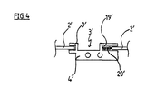
- Figure 4 shows an alternative embodiment of the invention in a top view.
- This points two rigid hooks 9 'and 19'.
- the first hook 9 ' is designed so that its length is shorter as the length of the second hook 19 '.
- a Spring 20 ' is between the hook 19 'and the holding device 4'.
- the spring 20 'connected to the holding device 4' can also be provided with the burner or the housing 2 'associated resilient nose, which extends between the hooks 19 'and the holding device 4'.
- the second hook 19' is brought into engagement with the housing 2 'of the burner, so that the Spring 20 'from the edge of the housing 2' is compressed.
- the holding device 4 ' is then pivoted about the hook 19 ', so that the hook 9' in the recess 3 'of the housing 2 'protrudes. If you let go of the holding device 4 ', so the first hook 9' also engages in the Housing 2 ', wherein the spring 20', the holding device with the hook 9 'against the housing 19' suppressed.
- the spring 20 ' is dispensed with while the hooks 9 ', 19' are resiliently biased from sheet metal against the housing 2 'and so the holding device 4' positively and non-positively connect with the housing 2 '.
Landscapes
- Engineering & Computer Science (AREA)
- Chemical & Material Sciences (AREA)
- Combustion & Propulsion (AREA)
- Mechanical Engineering (AREA)
- General Engineering & Computer Science (AREA)
- Control Of Combustion (AREA)
- Secondary Cells (AREA)
- Electron Tubes For Measurement (AREA)
- Ceramic Capacitors (AREA)
Abstract
Description
- Figur 1
- zeigt eine seitliche Ansicht einer erfindungsgemäßen Elektrodenanordnung.
- Figur 2
- zeigt eine Ansicht von oben der Elektrodenanordnung aus Figur 1.
- Figur 2A
- zeigt eine abgebrochene vergrößerte Ansicht der erfindungsgemäßen Rastfeder.
- Figur 3
- zeigt eine Ansicht von vorne der Elektrodenanordnung aus Figur 1.
- Figur 4
- zeigt eine Ansicht von oben auf eine alternative Ausführungsform der Erfindung.
- 1
- Brennfläche
- 2
- Gehäuse
- 3
- Ausnehmung
- 4
- Halteblech
- 5
- Hochspannungszündelektroden
- 6
- Hochspannungszündelektroden
- 7
- Isolatoren
- 8
- Isolatoren
- 9
- Rastnase
- 10
- Rastfeder
- 11
- Ende der Elektrode 5
- 12
- Ende der Elektrode 6
- 13
- Fixierlaschen
- 14
- Loch
- 15
- erste Rastrampe
- 16
- Totpunkt
- 17
- Rastvertiefung
- 18
- zweite Rastrampe
Claims (18)
- Elektrodenanordnung mit mindestens einer Elektrode (5,6), mindestens einer Halteeinrichtung (4) für die mindestens eine Elektrode (5,6) und mindestens einer Einrichtung (9, 10) zur Montage der Halteeinrichtung (4) an einem Brenner oder einer damit verbundenen Elektrodenhalterung (3), dadurch gekennzeichnet, daß die mindestens eine Einrichtung (9, 10) zur Montage ohne Werkzeug mit dem Brenner oder mit einer damit verbundenen Elektrodenhalterung (3) verbindbar ist.
- Elektrodenanordnung nach Anspruch 1, dadurch gekennzeichnet, daß die Einrichtung zur Montage ohne Werkzeug oder mit einem einfachen Werkzeug wieder von dem Brenner oder von einer damit verbundenen Elektrodenhalterung (3) lösbar ist.
- Elektrodenanordnung nach Anspruch 1 oder 2, dadurch gekennzeichnet, daß die Einrichtung zur Montage der Halteeinrichtung (4) mindestens ein starres Element (9) aufweist, das formschlüssig mit dem Brenner oder einer damit verbundenen Elektrodenhalterung (3) in Eingriff bringbar ist.
- Elektrodenanordnung nach Anspruch 3, dadurch gekennzeichnet, daß das mindestens eine starre Element ein Haken (9), eine Öse, eine Aussparung, eine Noppe oder ein Bolzen ist.
- Elektrodenanordnung nach einem der Ansprüche 1 bis 4, dadurch gekennzeichnet, daß die Vorrichtung zur Montage der Halteeinrichtung (4) mindestens ein flexibles Element (10) aufweist, das form- und/oder kraftschlüssig mit dem Brenner oder einer damit verbundenen Elektrodenhalterung (3) in Eingriff bringbar ist.
- Elektrodenanordnung nach Anspruch 5, dadurch gekennzeichnet, daß das mindestens eine flexible Element eine Rastfeder (10) ist.
- Elektrodenanordnung nach Anspruch 6, dadurch gekennzeichnet, daß die Rastfeder (10) eine erste Rastrampe (15) aufweist, welche bei der Montage zuerst mit der Elektrodenhalterung (3) in Eingriff tritt, daß die Rastfeder (10) einen Totpunkt (16) mit einer dahinter liegenden Rastvertiefung (17) aufweist, wobei die Elektrodenhalterung (3) nach dem Überschreiten des Totpunktes (16) in die Vertiefung (17) eingreift.
- Elektrodenanordnung nach Anspruch 7, dadurch gekennzeichnet, daß die Vertiefung (17) eine zweite Rastrampe (18) aufweist, wobei die zweite Rastrampe (18) steiler ist als die erste Rastrampe (15).
- Elektrodenanordnung nach Anspruch 5, dadurch gekennzeichnet, daß das mindestens eine flexible Element eine Rastnase ist.
- Elektrodenanordnung nach einem der Ansprüche 1 bis 9, dadurch gekennzeichnet, daß die Vorrichtung zur Montage der Halteeinrichtung mindestens ein magnetisches Element aufweist, welches mit einem metallischen oder magnetischen Element des Brenners in Eingriff bringbar ist.
- Elektrodenanordnung nach einem der Ansprüche 1 bis 10, dadurch gekennzeichnet, daß die Halteeinrichtung und die Elektrodenhalterung Elemente aufweisen, welche die Montage in nur einer Orientierung ermöglichen.
- Elektrodenanordnung nach einem der Ansprüche 1 bis 11, dadurch gekennzeichnet, daß jede der Elektroden eine Halteeinrichtung aufweist, wobei die Halteeinrichtungen einer jeden Elektrode getrennt voneinander an dem Brenner oder der Elektrodenhalterung des Brenners befestigbar sind.
- Elektrodenanordnung nach einem der Ansprüche 1 bis 12, dadurch gekennzeichnet, daß sie mindestens eine Hochspannungszündelektrode (5, 6) aufweist.
- Elektrodenanordnung nach einem der Ansprüche 1 bis 13, dadurch gekennzeichnet, daß sie mindestens eine Überwachungselektrode aufweist.
- Elektrodenanordnung nach einem der Ansprüche 1 bis 14, dadurch gekennzeichnet, daß die Halteeinrichtung ein Halteblech (4) ist.
- Elektrodenanordnung nach einem der Ansprüche 1 bis 14, dadurch gekennzeichnet, daß die Halteeinrichtung aus Kunststoff hergestellt ist.
- Elektrodenhalterung (3) für einen Brenner, dadurch gekennzeichnet, daß sie ein Aufnahmeelement für eine Elektrodenanordnung nach einem der Ansprüche 1 bis 16 aufweist.
- Elektrodenhalterung (3) für einen Brenner, dadurch gekennzeichnet, daß sie eine Einrichtung bzw. Elemente zur Montage der Elektrodenanordnung in kinematischer Umkehr zu der Einrichtung nach den Ansprüchen 1 bis 12 aufweist.
Priority Applications (1)
| Application Number | Priority Date | Filing Date | Title |
|---|---|---|---|
| PL05104799T PL1605206T3 (pl) | 2004-06-09 | 2005-06-02 | Zespół elektrod |
Applications Claiming Priority (2)
| Application Number | Priority Date | Filing Date | Title |
|---|---|---|---|
| DE102004028135 | 2004-06-09 | ||
| DE102004028135A DE102004028135A1 (de) | 2004-06-09 | 2004-06-09 | Elektrodenanordnung |
Publications (2)
| Publication Number | Publication Date |
|---|---|
| EP1605206A1 true EP1605206A1 (de) | 2005-12-14 |
| EP1605206B1 EP1605206B1 (de) | 2011-08-03 |
Family
ID=34993134
Family Applications (1)
| Application Number | Title | Priority Date | Filing Date |
|---|---|---|---|
| EP05104799A Expired - Lifetime EP1605206B1 (de) | 2004-06-09 | 2005-06-02 | Elektrodenanordnung |
Country Status (4)
| Country | Link |
|---|---|
| EP (1) | EP1605206B1 (de) |
| AT (1) | ATE519077T1 (de) |
| DE (1) | DE102004028135A1 (de) |
| PL (1) | PL1605206T3 (de) |
Cited By (3)
| Publication number | Priority date | Publication date | Assignee | Title |
|---|---|---|---|---|
| DE102006023841A1 (de) * | 2006-05-19 | 2007-11-22 | Viessmann Werke Gmbh & Co Kg | Elektrodenanordnung |
| EP2012060A1 (de) * | 2007-07-03 | 2009-01-07 | Siemens Aktiengesellschaft | Drei-Punkt-Fixierung von Zündelektroden eines Brenners |
| DE102017210590B4 (de) | 2017-06-23 | 2019-03-28 | Convotherm Elektrogeräte GmbH | Verbindungsvorrichtung für eine Elektrode |
Citations (4)
| Publication number | Priority date | Publication date | Assignee | Title |
|---|---|---|---|---|
| US3404940A (en) * | 1965-03-26 | 1968-10-08 | Chappuy Jean | Electrode holder for spark ignited oil burners |
| US3709740A (en) * | 1971-10-29 | 1973-01-09 | Robertshaw Controls Co | Thermocouple |
| US4861264A (en) | 1988-07-21 | 1989-08-29 | Channel Products, Inc. | Gas collector electrode assembly for gas burners |
| US6059479A (en) | 1998-03-13 | 2000-05-09 | Ensign Ribbon Burners, Llc | Pop-out electrode assembly |
Family Cites Families (5)
| Publication number | Priority date | Publication date | Assignee | Title |
|---|---|---|---|---|
| DE2444804C2 (de) * | 1974-09-19 | 1985-09-12 | Ibelo-Metallwarenfabrik Hermann Zahn KG, 6000 Frankfurt | Piezo-elektrisches Feuerzeug |
| DE8210282U1 (de) * | 1982-04-10 | 1982-09-09 | Honeywell B.V., Amsterdam | Haltevorrichtung fuer gasduese, thermoelement und zuendelektrode eines zuendbrenners |
| DE29520584U1 (de) * | 1994-12-27 | 1996-02-15 | Joh. Vaillant Gmbh U. Co, 42859 Remscheid | Elektrodenhalterung |
| DE19851958C2 (de) * | 1998-11-11 | 2000-09-07 | Heatec Thermotechnik Gmbh | Zündbrenner für Gasgeräte |
| DE10063664C1 (de) * | 2000-12-20 | 2002-07-11 | Wolf Gmbh | Elektrodeneinrichtung für Heizgeräte |
-
2004
- 2004-06-09 DE DE102004028135A patent/DE102004028135A1/de not_active Withdrawn
-
2005
- 2005-06-02 AT AT05104799T patent/ATE519077T1/de active
- 2005-06-02 EP EP05104799A patent/EP1605206B1/de not_active Expired - Lifetime
- 2005-06-02 PL PL05104799T patent/PL1605206T3/pl unknown
Patent Citations (4)
| Publication number | Priority date | Publication date | Assignee | Title |
|---|---|---|---|---|
| US3404940A (en) * | 1965-03-26 | 1968-10-08 | Chappuy Jean | Electrode holder for spark ignited oil burners |
| US3709740A (en) * | 1971-10-29 | 1973-01-09 | Robertshaw Controls Co | Thermocouple |
| US4861264A (en) | 1988-07-21 | 1989-08-29 | Channel Products, Inc. | Gas collector electrode assembly for gas burners |
| US6059479A (en) | 1998-03-13 | 2000-05-09 | Ensign Ribbon Burners, Llc | Pop-out electrode assembly |
Cited By (7)
| Publication number | Priority date | Publication date | Assignee | Title |
|---|---|---|---|---|
| DE102006023841A1 (de) * | 2006-05-19 | 2007-11-22 | Viessmann Werke Gmbh & Co Kg | Elektrodenanordnung |
| EP2012060A1 (de) * | 2007-07-03 | 2009-01-07 | Siemens Aktiengesellschaft | Drei-Punkt-Fixierung von Zündelektroden eines Brenners |
| WO2009003973A1 (de) * | 2007-07-03 | 2009-01-08 | Siemens Aktiengesellschaft | Drei-punkt-fixierung von zündelektroden eines brenners |
| CN101652608B (zh) * | 2007-07-03 | 2011-09-21 | 西门子公司 | 燃烧器的点火电极的三点定位装置 |
| RU2457399C2 (ru) * | 2007-07-03 | 2012-07-27 | Сименс Акциенгезелльшафт | Фиксация в трех точках поджигающих электродов горелки |
| US8590285B2 (en) | 2007-07-03 | 2013-11-26 | Siemens Aktiengesellschaft | Three-point fixing arrangement of ignition electrodes of a burner |
| DE102017210590B4 (de) | 2017-06-23 | 2019-03-28 | Convotherm Elektrogeräte GmbH | Verbindungsvorrichtung für eine Elektrode |
Also Published As
| Publication number | Publication date |
|---|---|
| ATE519077T1 (de) | 2011-08-15 |
| EP1605206B1 (de) | 2011-08-03 |
| PL1605206T3 (pl) | 2012-01-31 |
| DE102004028135A1 (de) | 2005-12-29 |
Similar Documents
| Publication | Publication Date | Title |
|---|---|---|
| EP3286806B1 (de) | Halterahmen zur halterung von steckverbindermodulen | |
| DE4001389C2 (de) | Fahrzeugscheinwerfer mit universeller Befestigungsmöglichkeit in verschiedenen Fahrzeugen | |
| DE102013113975C5 (de) | Halterahmen für einen Steckverbinder | |
| WO2010046376A1 (de) | Befestigungsstruktur, befestigungsvorrichtung und befestigungssystem zum befestigen einer ausrüstungskomponente in einem flugzeug | |
| EP1536519A1 (de) | Leiteranschluss | |
| DE102012107264A1 (de) | Anschlussmodul | |
| DE102017108320B4 (de) | Flachteilhalter für die Befestigung eines Flachteils an einem Rahmengestell eines Schaltschranks und ein entsprechender Schaltschrank | |
| EP3843221A1 (de) | Halterahmen für einen steckverbinder | |
| DE3220781A1 (de) | Kontaktelement zur loetfreien befestigung in leiterplatten-bohrungen | |
| EP2642613A2 (de) | Leuchtenmontagesystem | |
| EP1729326B1 (de) | Lampensockel und Lampe | |
| EP1605206B1 (de) | Elektrodenanordnung | |
| EP2432089A2 (de) | Gerätekombination zum Schutz vor Überspannungen | |
| DE102018203578A1 (de) | Anordnung zur elektrischen Verbindung von Polterminals sowie Zellmodul oder Batterie mit einer derartigen Verbindungsanordnung (I) | |
| EP1671399A1 (de) | Schirmanbindung | |
| DE4420072B4 (de) | Vorrichtung zum Anschließen elektrischer Leiter an einen Schaltapparat | |
| DE10063664C1 (de) | Elektrodeneinrichtung für Heizgeräte | |
| DE202014101093U1 (de) | Batterieklemme | |
| EP0981722B1 (de) | Messwerk | |
| DE202018101859U1 (de) | Vorrichtung zum Fixieren eines Batterietrogs eines Flurförderzeugs | |
| DE9310630U1 (de) | An einer Montagefläche befestigtes elektrisches Gerät | |
| DE102020121590A1 (de) | Verfahren zur Montage eines Abschirmelementes; Montageeinheit für das Verfahren und elektronisches Gerät mit Abschirmelement in thermisch aktivierbarer Abtrenneinrichtung | |
| DE102005061827B4 (de) | Computergehäuse | |
| DE102019129972A1 (de) | Markierungsvorrichtung zum Markieren von mit einer Prüfvorrichtung geprüften Schaltungskarten | |
| DE69211962T2 (de) | Steckdose, insbesondere für ein Kraftfahrzeug |
Legal Events
| Date | Code | Title | Description |
|---|---|---|---|
| PUAI | Public reference made under article 153(3) epc to a published international application that has entered the european phase |
Free format text: ORIGINAL CODE: 0009012 |
|
| AK | Designated contracting states |
Kind code of ref document: A1 Designated state(s): AT BE BG CH CY CZ DE DK EE ES FI FR GB GR HU IE IS IT LI LT LU MC NL PL PT RO SE SI SK TR |
|
| AX | Request for extension of the european patent |
Extension state: AL BA HR LV MK YU |
|
| 17P | Request for examination filed |
Effective date: 20051117 |
|
| AKX | Designation fees paid |
Designated state(s): AT BE BG CH CY CZ DE DK EE ES FI FR GB GR HU IE IS IT LI LT LU MC NL PL PT RO SE SI SK TR |
|
| 17Q | First examination report despatched |
Effective date: 20081027 |
|
| RAP1 | Party data changed (applicant data changed or rights of an application transferred) |
Owner name: PAUL RAUSCHERT GMBH & CO. KG |
|
| GRAP | Despatch of communication of intention to grant a patent |
Free format text: ORIGINAL CODE: EPIDOSNIGR1 |
|
| GRAJ | Information related to disapproval of communication of intention to grant by the applicant or resumption of examination proceedings by the epo deleted |
Free format text: ORIGINAL CODE: EPIDOSDIGR1 |
|
| GRAP | Despatch of communication of intention to grant a patent |
Free format text: ORIGINAL CODE: EPIDOSNIGR1 |
|
| GRAS | Grant fee paid |
Free format text: ORIGINAL CODE: EPIDOSNIGR3 |
|
| GRAA | (expected) grant |
Free format text: ORIGINAL CODE: 0009210 |
|
| AK | Designated contracting states |
Kind code of ref document: B1 Designated state(s): AT BE BG CH CY CZ DE DK EE ES FI FR GB GR HU IE IS IT LI LT LU MC NL PL PT RO SE SI SK TR |
|
| REG | Reference to a national code |
Ref country code: GB Ref legal event code: FG4D Free format text: NOT ENGLISH |
|
| REG | Reference to a national code |
Ref country code: CH Ref legal event code: EP |
|
| REG | Reference to a national code |
Ref country code: IE Ref legal event code: FG4D Free format text: LANGUAGE OF EP DOCUMENT: GERMAN |
|
| REG | Reference to a national code |
Ref country code: DE Ref legal event code: R096 Ref document number: 502005011715 Country of ref document: DE Effective date: 20110929 |
|
| REG | Reference to a national code |
Ref country code: NL Ref legal event code: T3 |
|
| LTIE | Lt: invalidation of european patent or patent extension |
Effective date: 20110803 |
|
| PG25 | Lapsed in a contracting state [announced via postgrant information from national office to epo] |
Ref country code: PT Free format text: LAPSE BECAUSE OF FAILURE TO SUBMIT A TRANSLATION OF THE DESCRIPTION OR TO PAY THE FEE WITHIN THE PRESCRIBED TIME-LIMIT Effective date: 20111205 Ref country code: LT Free format text: LAPSE BECAUSE OF FAILURE TO SUBMIT A TRANSLATION OF THE DESCRIPTION OR TO PAY THE FEE WITHIN THE PRESCRIBED TIME-LIMIT Effective date: 20110803 Ref country code: SE Free format text: LAPSE BECAUSE OF FAILURE TO SUBMIT A TRANSLATION OF THE DESCRIPTION OR TO PAY THE FEE WITHIN THE PRESCRIBED TIME-LIMIT Effective date: 20110803 Ref country code: IS Free format text: LAPSE BECAUSE OF FAILURE TO SUBMIT A TRANSLATION OF THE DESCRIPTION OR TO PAY THE FEE WITHIN THE PRESCRIBED TIME-LIMIT Effective date: 20111203 Ref country code: FI Free format text: LAPSE BECAUSE OF FAILURE TO SUBMIT A TRANSLATION OF THE DESCRIPTION OR TO PAY THE FEE WITHIN THE PRESCRIBED TIME-LIMIT Effective date: 20110803 |
|
| REG | Reference to a national code |
Ref country code: PL Ref legal event code: T3 |
|
| PG25 | Lapsed in a contracting state [announced via postgrant information from national office to epo] |
Ref country code: CY Free format text: LAPSE BECAUSE OF FAILURE TO SUBMIT A TRANSLATION OF THE DESCRIPTION OR TO PAY THE FEE WITHIN THE PRESCRIBED TIME-LIMIT Effective date: 20110803 Ref country code: SI Free format text: LAPSE BECAUSE OF FAILURE TO SUBMIT A TRANSLATION OF THE DESCRIPTION OR TO PAY THE FEE WITHIN THE PRESCRIBED TIME-LIMIT Effective date: 20110803 Ref country code: GR Free format text: LAPSE BECAUSE OF FAILURE TO SUBMIT A TRANSLATION OF THE DESCRIPTION OR TO PAY THE FEE WITHIN THE PRESCRIBED TIME-LIMIT Effective date: 20111104 |
|
| REG | Reference to a national code |
Ref country code: IE Ref legal event code: FD4D |
|
| PG25 | Lapsed in a contracting state [announced via postgrant information from national office to epo] |
Ref country code: IE Free format text: LAPSE BECAUSE OF FAILURE TO SUBMIT A TRANSLATION OF THE DESCRIPTION OR TO PAY THE FEE WITHIN THE PRESCRIBED TIME-LIMIT Effective date: 20110803 Ref country code: CZ Free format text: LAPSE BECAUSE OF FAILURE TO SUBMIT A TRANSLATION OF THE DESCRIPTION OR TO PAY THE FEE WITHIN THE PRESCRIBED TIME-LIMIT Effective date: 20110803 Ref country code: SK Free format text: LAPSE BECAUSE OF FAILURE TO SUBMIT A TRANSLATION OF THE DESCRIPTION OR TO PAY THE FEE WITHIN THE PRESCRIBED TIME-LIMIT Effective date: 20110803 |
|
| PG25 | Lapsed in a contracting state [announced via postgrant information from national office to epo] |
Ref country code: RO Free format text: LAPSE BECAUSE OF FAILURE TO SUBMIT A TRANSLATION OF THE DESCRIPTION OR TO PAY THE FEE WITHIN THE PRESCRIBED TIME-LIMIT Effective date: 20110803 Ref country code: EE Free format text: LAPSE BECAUSE OF FAILURE TO SUBMIT A TRANSLATION OF THE DESCRIPTION OR TO PAY THE FEE WITHIN THE PRESCRIBED TIME-LIMIT Effective date: 20110803 |
|
| PLBE | No opposition filed within time limit |
Free format text: ORIGINAL CODE: 0009261 |
|
| STAA | Information on the status of an ep patent application or granted ep patent |
Free format text: STATUS: NO OPPOSITION FILED WITHIN TIME LIMIT |
|
| PG25 | Lapsed in a contracting state [announced via postgrant information from national office to epo] |
Ref country code: DK Free format text: LAPSE BECAUSE OF FAILURE TO SUBMIT A TRANSLATION OF THE DESCRIPTION OR TO PAY THE FEE WITHIN THE PRESCRIBED TIME-LIMIT Effective date: 20110803 |
|
| 26N | No opposition filed |
Effective date: 20120504 |
|
| REG | Reference to a national code |
Ref country code: DE Ref legal event code: R097 Ref document number: 502005011715 Country of ref document: DE Effective date: 20120504 |
|
| BERE | Be: lapsed |
Owner name: PAUL RAUSCHERT G.M.B.H. & CO. KG Effective date: 20120630 |
|
| PG25 | Lapsed in a contracting state [announced via postgrant information from national office to epo] |
Ref country code: MC Free format text: LAPSE BECAUSE OF NON-PAYMENT OF DUE FEES Effective date: 20120630 |
|
| REG | Reference to a national code |
Ref country code: CH Ref legal event code: PL |
|
| REG | Reference to a national code |
Ref country code: CH Ref legal event code: PL |
|
| PG25 | Lapsed in a contracting state [announced via postgrant information from national office to epo] |
Ref country code: BE Free format text: LAPSE BECAUSE OF NON-PAYMENT OF DUE FEES Effective date: 20120630 Ref country code: LI Free format text: LAPSE BECAUSE OF NON-PAYMENT OF DUE FEES Effective date: 20120630 Ref country code: ES Free format text: LAPSE BECAUSE OF FAILURE TO SUBMIT A TRANSLATION OF THE DESCRIPTION OR TO PAY THE FEE WITHIN THE PRESCRIBED TIME-LIMIT Effective date: 20111114 Ref country code: CH Free format text: LAPSE BECAUSE OF NON-PAYMENT OF DUE FEES Effective date: 20120630 |
|
| PG25 | Lapsed in a contracting state [announced via postgrant information from national office to epo] |
Ref country code: BG Free format text: LAPSE BECAUSE OF FAILURE TO SUBMIT A TRANSLATION OF THE DESCRIPTION OR TO PAY THE FEE WITHIN THE PRESCRIBED TIME-LIMIT Effective date: 20111103 |
|
| REG | Reference to a national code |
Ref country code: AT Ref legal event code: MM01 Ref document number: 519077 Country of ref document: AT Kind code of ref document: T Effective date: 20120602 |
|
| PG25 | Lapsed in a contracting state [announced via postgrant information from national office to epo] |
Ref country code: PL Free format text: LAPSE BECAUSE OF NON-PAYMENT OF DUE FEES Effective date: 20120602 |
|
| REG | Reference to a national code |
Ref country code: PL Ref legal event code: LAPE |
|
| PG25 | Lapsed in a contracting state [announced via postgrant information from national office to epo] |
Ref country code: AT Free format text: LAPSE BECAUSE OF NON-PAYMENT OF DUE FEES Effective date: 20120602 |
|
| PG25 | Lapsed in a contracting state [announced via postgrant information from national office to epo] |
Ref country code: LU Free format text: LAPSE BECAUSE OF NON-PAYMENT OF DUE FEES Effective date: 20120602 |
|
| PG25 | Lapsed in a contracting state [announced via postgrant information from national office to epo] |
Ref country code: HU Free format text: LAPSE BECAUSE OF FAILURE TO SUBMIT A TRANSLATION OF THE DESCRIPTION OR TO PAY THE FEE WITHIN THE PRESCRIBED TIME-LIMIT Effective date: 20050602 |
|
| REG | Reference to a national code |
Ref country code: FR Ref legal event code: PLFP Year of fee payment: 12 |
|
| REG | Reference to a national code |
Ref country code: FR Ref legal event code: PLFP Year of fee payment: 13 |
|
| REG | Reference to a national code |
Ref country code: FR Ref legal event code: PLFP Year of fee payment: 14 |
|
| PGFP | Annual fee paid to national office [announced via postgrant information from national office to epo] |
Ref country code: GB Payment date: 20240619 Year of fee payment: 20 |
|
| PGFP | Annual fee paid to national office [announced via postgrant information from national office to epo] |
Ref country code: DE Payment date: 20240620 Year of fee payment: 20 |
|
| PGFP | Annual fee paid to national office [announced via postgrant information from national office to epo] |
Ref country code: NL Payment date: 20240619 Year of fee payment: 20 |
|
| PGFP | Annual fee paid to national office [announced via postgrant information from national office to epo] |
Ref country code: FR Payment date: 20240628 Year of fee payment: 20 |
|
| PGFP | Annual fee paid to national office [announced via postgrant information from national office to epo] |
Ref country code: TR Payment date: 20240524 Year of fee payment: 20 |
|
| PGFP | Annual fee paid to national office [announced via postgrant information from national office to epo] |
Ref country code: IT Payment date: 20240625 Year of fee payment: 20 |
|
| REG | Reference to a national code |
Ref country code: DE Ref legal event code: R071 Ref document number: 502005011715 Country of ref document: DE |
|
| REG | Reference to a national code |
Ref country code: NL Ref legal event code: MK Effective date: 20250601 |
|
| REG | Reference to a national code |
Ref country code: GB Ref legal event code: PE20 Expiry date: 20250601 |
|
| PG25 | Lapsed in a contracting state [announced via postgrant information from national office to epo] |
Ref country code: GB Free format text: LAPSE BECAUSE OF EXPIRATION OF PROTECTION Effective date: 20250601 |