EP1605237A1 - Machine d'usinage laser avec un dispositif de surveillance du faisceau et méthode correspondante pour déterminer au moins une caractéristique d'un faisceau laser - Google Patents
Machine d'usinage laser avec un dispositif de surveillance du faisceau et méthode correspondante pour déterminer au moins une caractéristique d'un faisceau laser Download PDFInfo
- Publication number
- EP1605237A1 EP1605237A1 EP04013314A EP04013314A EP1605237A1 EP 1605237 A1 EP1605237 A1 EP 1605237A1 EP 04013314 A EP04013314 A EP 04013314A EP 04013314 A EP04013314 A EP 04013314A EP 1605237 A1 EP1605237 A1 EP 1605237A1
- Authority
- EP
- European Patent Office
- Prior art keywords
- laser
- processing machine
- laser processing
- detection element
- laser beam
- Prior art date
- Legal status (The legal status is an assumption and is not a legal conclusion. Google has not performed a legal analysis and makes no representation as to the accuracy of the status listed.)
- Ceased
Links
Images

Classifications
-
- G—PHYSICS
- G01—MEASURING; TESTING
- G01J—MEASUREMENT OF INTENSITY, VELOCITY, SPECTRAL CONTENT, POLARISATION, PHASE OR PULSE CHARACTERISTICS OF INFRARED, VISIBLE OR ULTRAVIOLET LIGHT; COLORIMETRY; RADIATION PYROMETRY
- G01J1/00—Photometry, e.g. photographic exposure meter
- G01J1/42—Photometry, e.g. photographic exposure meter using electric radiation detectors
- G01J1/4257—Photometry, e.g. photographic exposure meter using electric radiation detectors applied to monitoring the characteristics of a beam, e.g. laser beam, headlamp beam
-
- B—PERFORMING OPERATIONS; TRANSPORTING
- B23—MACHINE TOOLS; METAL-WORKING NOT OTHERWISE PROVIDED FOR
- B23K—SOLDERING OR UNSOLDERING; WELDING; CLADDING OR PLATING BY SOLDERING OR WELDING; CUTTING BY APPLYING HEAT LOCALLY, e.g. FLAME CUTTING; WORKING BY LASER BEAM
- B23K26/00—Working by laser beam, e.g. welding, cutting or boring
- B23K26/08—Devices involving relative movement between laser beam and workpiece
- B23K26/10—Devices involving relative movement between laser beam and workpiece using a fixed support, i.e. involving moving the laser beam
-
- B—PERFORMING OPERATIONS; TRANSPORTING
- B23—MACHINE TOOLS; METAL-WORKING NOT OTHERWISE PROVIDED FOR
- B23K—SOLDERING OR UNSOLDERING; WELDING; CLADDING OR PLATING BY SOLDERING OR WELDING; CUTTING BY APPLYING HEAT LOCALLY, e.g. FLAME CUTTING; WORKING BY LASER BEAM
- B23K26/00—Working by laser beam, e.g. welding, cutting or boring
- B23K26/70—Auxiliary operations or equipment
- B23K26/702—Auxiliary equipment
Definitions
- the invention relates to a laser processing machine for processing of workpieces, with a functional unit and a Function drive, by means of which, under movement of the assigned Function unit of the beam focus of a laser beam and a Workpiece for workpiece machining relative to each other positionable and / or are movable.
- the invention further relates a method for determining at least one beam characteristic a laser beam on a laser processing machine, wherein for beam diagnosis, a beam detection element of a Beam diagnosis device and the laser beam under sectoral Detection of the laser beam cross-section through the beam detection element moved relative to each other in the beam transverse direction become.
- Laser processing machines of the type mentioned are, for example as laser cutting or laser welding machines in various design known.
- For workpiece machining are relative movements of the beam focus of the Machining tool used laser beam and the processed Execute workpiece. Such relative movements can for example along the workpiece surface to be machined but also - about to focus position adjustment before and during machining - directed transversely to the workpiece surface be.
- For executing the machining-related relative movements serve in the case of the prior art function drives the laser processing machine, which is usually numerical are controlled.
- beam diagnostic devices by means of which according to the method mentioned beam characteristics of a Laser beam to be determined on a laser processing machine.
- a corresponding beam diagnostic device is of the Company PROMETEC GmbH, 52070 Aachen, DE under the name "LASERSCOPE UFF 100" sold.
- Printed publications are a beam diagnostic device and a beam diagnostic method of the above type in DE 199 09 595 A1.
- the known beam diagnostic devices are independent orders that are self-sufficient and, if necessary, also on self-contained laser processing machines be used.
- a simplification of the existing conditions has the present invention aims.
- the invention is therefore a beam diagnostic device integrated into a laser processing machine.
- the for the Beam diagnosis required relative movement of the relevant Laser beam and a beam detection element of the beam diagnostic device is by means of a functional drive of the laser processing machine executed.
- This functional drive otherwise serves for the processing-related relative movement of the Beam focus of the laser beam and the workpiece to be machined.
- Functional drives in question usually on laser processing machines are provided.
- the acquisition cost for a Laser processing machine with the possibility of a laser beam diagnosis consequently reduces to a minimum.
- the Beam diagnosis in the case of the invention is one of the functions the relevant laser processing machine.
- Laser processing machine is characterized by a particularly high level of integration.
- this laser processing machine Not only the mechanical components of a Function drive of the laser processing machine but In addition, also components of the associated numerical Control used twice.
- the beam diagnostic device and the laser beam must be the position of the laser beam in a frame of reference the laser processing machine defined and known be.
- the laser processing machine according to claim 2 become the position information for both relative movements provided by one and the same control module.
- kinematic reversal of the conditions according to claim 6 are at the laser processing machine according to the invention according to claim 8, the possibilities of movement the workpiece during machining stored workpiece storage used for beam diagnostics.
- a beam detection element of Beam diagnostic device becomes common with the workpiece storage moved relative to the laser beam. This measure is advantageous insofar as the relevant laser beam throughout the beam diagnostics in a consistent state located. State changes that occur during movement of the Laser beam, for example, due to adjustments associated with the movement could result in the laser beam guide are avoided.
- Claim 9 describes an embodiment of the invention Laser processing machine with a beam diagnostic device, the one provision of in the operational Practice often required beam characteristics allowed.
- the invention as a beam detection element, a temperature sensor intended. Based on the temperature conditions is a conclusion possible on a variety of laser beam features.
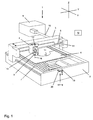
- FIG. 1 has a trained as a laser cutting machine 1
- Laser processing machine a machine bed 2, on which a machine bridge 3 in a first axial direction (x-direction) movably guided.
- the machine bridge 3 stores in turn on a cross member with a guide carriage 4 a laser machining head or laser cutting head shown broken away 5 as a functional unit.
- Communicating with the Guide carriage 4 is the laser cutting head 5 in a second Axial direction (y-direction) on the crossbeam of the machine bridge 3 movable along.
- the laser cutting head 5 relative to the guide carriage 4 in a third axial direction (z-direction) movable.
- Below the laser cutting head 5 is a workpiece in the form of a sheet 6 on an inside the machine bed 2 arranged workpiece support 7 stored.
- the of a laser beam source 9 is generated.
- the laser beam 8 passes through a beam guide tube 10 to the machine bridge 3.
- the second deflecting mirror 12 reflects the laser beam 8 to a Focusing lens 13, which bundles the laser beam 8 and as a processing beam directed to the plate 6.
- the machine bridge 3 in the x direction and the guide carriage 4 in the y-direction can be any with the laser beam 8 Point to be approached to the plate 6.
- One in the shown Example case on the sheet 6 created section 14 is indicated in Fig. 1.
- the mobility of the laser cutting head 5 in the z-direction is used to adjust the focus position of the laser beam 8 used in sheet metal transverse direction. Such a focus position adjustment can before the workpiece machining, but also in the current cutting operation.
- For moving the laser cutting head 5 in the three directions of the Room serves a motor functional drive with a numerical Control 15.
- a numerical control 15 Drive devices for moving the machine bridge 3 in x-direction, drive means for moving the guide carriage 4 in y-direction and drive means for movement of the laser cutting head 5 in the z-direction coordinated controlled. Also the other functions of the laser cutting machine 1 are control related in the numerical control 15 integrated.
- a sensor arrangement 17th a beam diagnostic device 18 attached.
- the sensor arrangement comprises 17 a cooled aperture plate 19 and one arranged underneath Temperature sensor 20 as a beam detection element. Of the Temperature sensor 20 is connected to an evaluation of the Beam diagnostic device 18 in conjunction, which in turn in the numerical control 15 of the laser cutting machine 1 integrated is. On the machine bed 2, the sensor assembly 17 adjustable in z-direction.
- Beam characteristics include i.a. the beam intensity distribution in Cross section of the laser beam 8 and the position of the vertical extending portion of the laser beam 8 and the beam axis 16 in the room.
- the machine bridge 3 with the guide carriage 4 and the laser cutting head 5 by means of the relevant drive to that with the sensor arrangement 17th moved provided end of the machine bed 2.
- the Laser cutting head 5 including the focusing lens 13 dismantled dismantled.
- the laser beam 8 by means of the second Deflection mirror 12 on the guide carriage 4 on the sensor assembly 17 directed (Fig. 2).
- the laser beam 8 By moving the machine bridge 3 and the guide carriage 4, the laser beam 8 in the x and y direction over the Opening the pinhole 19 out.
- the opening cross section of Aperture 19 is smaller than the cross section of the laser beam 8.
- Through the opening of the pinhole 19 thus passes respectively only one area of the beam cross-section on the temperature sensor 20.
- the temperature sensor 20 thus scans the beam cross section the laser beam 8 in areas.
- the evaluation device of the beam diagnostic device 18 By means of the evaluation device of the beam diagnostic device 18 becomes each recorded and defined cross-sectional area the laser beam 8 associated there with the detected temperature.
- the individual cross-sectional areas with the respective temperatures then become the beam overall cross-section with the composed over this adjusting temperature profile. In this way, the beam intensity distribution in Cross section of the laser beam 8 determined.
- the data obtained by the beam diagnostic device 18 are used Findings for optimizing with the laser cutting machine 1 performed workpiece machining.
Landscapes
- Physics & Mathematics (AREA)
- Optics & Photonics (AREA)
- Engineering & Computer Science (AREA)
- Plasma & Fusion (AREA)
- Mechanical Engineering (AREA)
- General Physics & Mathematics (AREA)
- Spectroscopy & Molecular Physics (AREA)
- Laser Beam Processing (AREA)
Priority Applications (3)
| Application Number | Priority Date | Filing Date | Title |
|---|---|---|---|
| EP04013314A EP1605237A1 (fr) | 2004-06-05 | 2004-06-05 | Machine d'usinage laser avec un dispositif de surveillance du faisceau et méthode correspondante pour déterminer au moins une caractéristique d'un faisceau laser |
| DE202004021725U DE202004021725U1 (de) | 2004-06-05 | 2004-06-05 | Laserbearbeitungsmaschine mit Strahldiagnosevorrichtung zur Bestimmung wenigstens eines Strahlkenndatums eines Laserstrahls an einer Laserbearbeitungsmaschine |
| US11/145,481 US20050269302A1 (en) | 2004-06-05 | 2005-06-03 | Laser machine tool with beam analyzer |
Applications Claiming Priority (1)
| Application Number | Priority Date | Filing Date | Title |
|---|---|---|---|
| EP04013314A EP1605237A1 (fr) | 2004-06-05 | 2004-06-05 | Machine d'usinage laser avec un dispositif de surveillance du faisceau et méthode correspondante pour déterminer au moins une caractéristique d'un faisceau laser |
Publications (1)
| Publication Number | Publication Date |
|---|---|
| EP1605237A1 true EP1605237A1 (fr) | 2005-12-14 |
Family
ID=34925265
Family Applications (1)
| Application Number | Title | Priority Date | Filing Date |
|---|---|---|---|
| EP04013314A Ceased EP1605237A1 (fr) | 2004-06-05 | 2004-06-05 | Machine d'usinage laser avec un dispositif de surveillance du faisceau et méthode correspondante pour déterminer au moins une caractéristique d'un faisceau laser |
Country Status (3)
| Country | Link |
|---|---|
| US (1) | US20050269302A1 (fr) |
| EP (1) | EP1605237A1 (fr) |
| DE (1) | DE202004021725U1 (fr) |
Cited By (1)
| Publication number | Priority date | Publication date | Assignee | Title |
|---|---|---|---|---|
| CN102099146A (zh) * | 2008-05-02 | 2011-06-15 | 通快机床两合公司 | 用于分析激光光束的光束剖面的装置 |
Families Citing this family (11)
| Publication number | Priority date | Publication date | Assignee | Title |
|---|---|---|---|---|
| DE102008027138A1 (de) * | 2008-05-30 | 2009-12-03 | Gas - Automation Gmbh | Werkstückträger für eine Trenneinrichtung für flächenhafte Werkstücke sowie Trenneinrichtung |
| DE202010016854U1 (de) | 2010-12-22 | 2011-12-29 | Anton W. HUBERT | Schneidvorrichtung |
| JP5459255B2 (ja) * | 2011-04-08 | 2014-04-02 | 株式会社安川電機 | ロボットシステム |
| US9718148B2 (en) | 2014-08-07 | 2017-08-01 | Machitech Automation | Guiding assembly for a workpiece cutting apparatus, workpiece cutting apparatus including the same, and method for displacing a cutting assembly along a workpiece cutting table |
| CN104816090A (zh) * | 2015-05-27 | 2015-08-05 | 深圳市奥斯玛数控发展有限公司 | 激光机床 |
| JP6348149B2 (ja) * | 2016-07-08 | 2018-06-27 | ファナック株式会社 | ロボットを用いてレーザ加工を行うレーザ加工ロボットシステム |
| JP6464213B2 (ja) * | 2017-02-09 | 2019-02-06 | ファナック株式会社 | レーザ加工ヘッドおよび撮影装置を備えるレーザ加工システム |
| KR102490377B1 (ko) * | 2017-05-05 | 2023-01-19 | 일렉트로 싸이언티픽 인더스트리이즈 인코포레이티드 | 다중 축 공작 기계, 이를 제어하는 방법들 및 관련 배치들 |
| CN107186362A (zh) * | 2017-06-28 | 2017-09-22 | 惠州市柯帝士科技有限公司 | 激光切割方法 |
| JP7365289B2 (ja) * | 2020-04-23 | 2023-10-19 | 株式会社アマダ | スキッド状態判定装置、スキッド状態判定方法及びレーザ加工システム |
| CN114646385B (zh) * | 2022-03-04 | 2025-12-02 | 长沙麓邦光电科技有限公司 | 一种传播光场检测系统及方法 |
Citations (4)
| Publication number | Priority date | Publication date | Assignee | Title |
|---|---|---|---|---|
| EP0421135A2 (fr) * | 1989-10-04 | 1991-04-10 | DORRIES SCHARMANN GmbH | Méthode et procédé pour la détermination de la position et du diamètre de la tache focale d'un rayon laser, en particulier pour l'usinage de matériaux avec un laser haute puissance |
| WO1996008027A1 (fr) | 1994-09-07 | 1996-03-14 | Lumonics Corporation | Systeme de mesure de faisceau laser concentre et procede de positionnement de faisceau |
| DE19909595A1 (de) | 1999-03-04 | 2000-09-07 | Primes Gmbh | Verfahren und Vorrichtung zur Vermessung der räumlichen Leistungsdichteverteilung von Strahlung hoher Divergenz und hoher Leistung |
| EP1083091A2 (fr) | 1999-09-07 | 2001-03-14 | Fischerwerke Arthur Fischer GmbH & Co. KG | Compartiment d'emmagasinage d'un conteneur, notamment dans un véhicule |
Family Cites Families (5)
| Publication number | Priority date | Publication date | Assignee | Title |
|---|---|---|---|---|
| US5154707A (en) * | 1987-02-27 | 1992-10-13 | Rink Dan L | Method and apparatus for external control of surgical lasers |
| DE19943043C2 (de) | 1999-09-09 | 2001-09-13 | Trumpf Gmbh & Co | Maschine und Verfahren zum thermischen Schneiden, insbesondere zum Laserschneiden, von Werkstücken |
| US6528762B2 (en) * | 2001-02-12 | 2003-03-04 | W. A. Whitney Co. | Laser beam position control apparatus for a CNC laser equipped machine tool |
| US6609545B1 (en) * | 2001-06-15 | 2003-08-26 | Ian Van Gelder | Wood cutting head structure |
| US6596961B2 (en) * | 2001-09-12 | 2003-07-22 | Fraunhofer Usa, Inc. | Method and apparatus for monitoring and adjusting a laser welding process |
-
2004
- 2004-06-05 EP EP04013314A patent/EP1605237A1/fr not_active Ceased
- 2004-06-05 DE DE202004021725U patent/DE202004021725U1/de not_active Expired - Lifetime
-
2005
- 2005-06-03 US US11/145,481 patent/US20050269302A1/en not_active Abandoned
Patent Citations (4)
| Publication number | Priority date | Publication date | Assignee | Title |
|---|---|---|---|---|
| EP0421135A2 (fr) * | 1989-10-04 | 1991-04-10 | DORRIES SCHARMANN GmbH | Méthode et procédé pour la détermination de la position et du diamètre de la tache focale d'un rayon laser, en particulier pour l'usinage de matériaux avec un laser haute puissance |
| WO1996008027A1 (fr) | 1994-09-07 | 1996-03-14 | Lumonics Corporation | Systeme de mesure de faisceau laser concentre et procede de positionnement de faisceau |
| DE19909595A1 (de) | 1999-03-04 | 2000-09-07 | Primes Gmbh | Verfahren und Vorrichtung zur Vermessung der räumlichen Leistungsdichteverteilung von Strahlung hoher Divergenz und hoher Leistung |
| EP1083091A2 (fr) | 1999-09-07 | 2001-03-14 | Fischerwerke Arthur Fischer GmbH & Co. KG | Compartiment d'emmagasinage d'un conteneur, notamment dans un véhicule |
Cited By (3)
| Publication number | Priority date | Publication date | Assignee | Title |
|---|---|---|---|---|
| CN102099146A (zh) * | 2008-05-02 | 2011-06-15 | 通快机床两合公司 | 用于分析激光光束的光束剖面的装置 |
| US8480300B2 (en) | 2008-05-02 | 2013-07-09 | Trumpf Werkzeugmaschinen Gmbh + Co. Kg | Device for analyzing a beam profile of a laser beam |
| CN102099146B (zh) * | 2008-05-02 | 2015-01-14 | 通快机床两合公司 | 用于分析激光光束的光束剖面的装置 |
Also Published As
| Publication number | Publication date |
|---|---|
| US20050269302A1 (en) | 2005-12-08 |
| DE202004021725U1 (de) | 2010-07-15 |
Similar Documents
| Publication | Publication Date | Title |
|---|---|---|
| EP3532238B1 (fr) | Unité de déviation comprenant deux fenêtres, un élément optique et un dispositif de déviation xy | |
| EP2284486B1 (fr) | Appareil de mesure de coordonnées et procédé de mesure à l'aide d'un appareil de mesure de coordonnées | |
| EP1133377B1 (fr) | Dispositif et procede de balayage de la surface d'un objet a l'aide d'un faisceau laser | |
| DE102011054941B3 (de) | Vorrichtung und Verfahren zur Korrektur der thermischen Verschiebung der Fokuslage von über Optiken geführten Laserstrahlen | |
| EP4121247B1 (fr) | Procédé et dispositif pour déterminer un état réel de barres de support d'un support de pièce, et machine-outil équipée d'un tel dispositif | |
| DE202004021725U1 (de) | Laserbearbeitungsmaschine mit Strahldiagnosevorrichtung zur Bestimmung wenigstens eines Strahlkenndatums eines Laserstrahls an einer Laserbearbeitungsmaschine | |
| WO2018219860A1 (fr) | Procédé et dispositif pour la surveillance d'un processus d'usinage laser | |
| DE102021002040A1 (de) | Schweißvorrichtung und Verfahren zum Verbinden eines ersten Werkstücks mit einem zweiten Werkstück durch Laserschweißen | |
| DE102007019453B4 (de) | Koordinatenmessgerät mit zwei Schlitten auf gemeinsamer Führung | |
| DE102018217940A1 (de) | Verfahren und Bearbeitungsmaschine zum Bearbeiten eines Werkstücks | |
| DE19960017A1 (de) | Härteprüfvorrichtung | |
| DE102017213511A1 (de) | Verfahren zur Lasermaterialbearbeitung und Lasermaschine | |
| DE10250326A1 (de) | Werkzeugmaschine und Verfahren zur Justage der Spindelposition dieser Werkzeugmaschine | |
| EP2091699A2 (fr) | Procédé et dispositif pour le positionnement fin d'un outil avec un organe de manipulation | |
| DE102009012543A1 (de) | Schneidevorrichtung | |
| EP3566793B1 (fr) | Détection de matière en excès à couper pour cellules de pliage | |
| EP2648666B1 (fr) | Dispositif laser destiné notamment à la chirurgie laser ophtalmologique | |
| DE102018211166A1 (de) | Verfahren und Vorrichtung zum Überprüfen einer Fokuslage eines Laserstrahls relativ zu einem Werkstück | |
| DE102005038587A1 (de) | Messsystem und Verfahren zum Vermessen eines Laserstrahls | |
| DE19655127C2 (de) | Anschlußkopf zur Bearbeitung eines Werkstücks mittels eines Laserstrahls | |
| AT526197B1 (de) | Verfahren zum Ermitteln von, insbesondere statischen, Geometriefehlern einer Lasermaschine zum Schneiden, Gravieren, Markieren und/oder Beschriften eines Werkstückes und ein Verfahren zum Ermitteln der Lage bzw. Position des Mittelpunkts eines Detektors am Detektorelement sowie Kalibrier-Segment und Lasermaschine hierfür | |
| DE102010027910A1 (de) | Rapid Technologie System mit einem einen Lichtstrahl emittierenden Laser | |
| EP3515627B1 (fr) | Machine-outil et procédé d'usinage de pièces en forme de plaque | |
| DE19828723A1 (de) | Laserbearbeitungseinrichtung | |
| DE202011003825U1 (de) | Bearbeitungsmaschine, insbesondere Laserbearbeitungsmaschine |
Legal Events
| Date | Code | Title | Description |
|---|---|---|---|
| PUAI | Public reference made under article 153(3) epc to a published international application that has entered the european phase |
Free format text: ORIGINAL CODE: 0009012 |
|
| AK | Designated contracting states |
Kind code of ref document: A1 Designated state(s): AT BE BG CH CY CZ DE DK EE ES FI FR GB GR HU IE IT LI LU MC NL PL PT RO SE SI SK TR |
|
| AX | Request for extension of the european patent |
Extension state: AL HR LT LV MK |
|
| 17P | Request for examination filed |
Effective date: 20060524 |
|
| 17Q | First examination report despatched |
Effective date: 20060622 |
|
| AKX | Designation fees paid |
Designated state(s): AT BE BG CH CY CZ DE DK EE ES FI FR GB GR HU IE IT LI LU MC NL PL PT RO SE SI SK TR |
|
| 17Q | First examination report despatched |
Effective date: 20060622 |
|
| STAA | Information on the status of an ep patent application or granted ep patent |
Free format text: STATUS: THE APPLICATION HAS BEEN REFUSED |
|
| 18R | Application refused |
Effective date: 20100221 |