EP1605593A2 - Circuit de commande d'une armature sanitaire - Google Patents
Circuit de commande d'une armature sanitaire Download PDFInfo
- Publication number
- EP1605593A2 EP1605593A2 EP05011996A EP05011996A EP1605593A2 EP 1605593 A2 EP1605593 A2 EP 1605593A2 EP 05011996 A EP05011996 A EP 05011996A EP 05011996 A EP05011996 A EP 05011996A EP 1605593 A2 EP1605593 A2 EP 1605593A2
- Authority
- EP
- European Patent Office
- Prior art keywords
- pulse
- capacitive sensor
- circuit
- mode
- circuit arrangement
- Prior art date
- Legal status (The legal status is an assumption and is not a legal conclusion. Google has not performed a legal analysis and makes no representation as to the accuracy of the status listed.)
- Withdrawn
Links
- 238000011156 evaluation Methods 0.000 claims abstract description 45
- XLYOFNOQVPJJNP-UHFFFAOYSA-N water Substances O XLYOFNOQVPJJNP-UHFFFAOYSA-N 0.000 claims abstract description 12
- 230000001960 triggered effect Effects 0.000 claims abstract description 4
- 238000001208 nuclear magnetic resonance pulse sequence Methods 0.000 claims description 9
- 238000013459 approach Methods 0.000 claims description 7
- 238000001514 detection method Methods 0.000 claims 2
- 230000004913 activation Effects 0.000 claims 1
- 230000008859 change Effects 0.000 description 8
- 238000000034 method Methods 0.000 description 7
- 230000008569 process Effects 0.000 description 5
- 230000007704 transition Effects 0.000 description 4
- 238000012790 confirmation Methods 0.000 description 3
- 230000002747 voluntary effect Effects 0.000 description 3
- 230000004888 barrier function Effects 0.000 description 2
- 238000011010 flushing procedure Methods 0.000 description 2
- 230000008672 reprogramming Effects 0.000 description 2
- 230000008901 benefit Effects 0.000 description 1
- 238000010586 diagram Methods 0.000 description 1
- 230000006870 function Effects 0.000 description 1
- 230000000717 retained effect Effects 0.000 description 1
Images


Classifications
-
- H—ELECTRICITY
- H03—ELECTRONIC CIRCUITRY
- H03K—PULSE TECHNIQUE
- H03K17/00—Electronic switching or gating, i.e. not by contact-making and –breaking
- H03K17/94—Electronic switching or gating, i.e. not by contact-making and –breaking characterised by the way in which the control signals are generated
- H03K17/945—Proximity switches
- H03K17/955—Proximity switches using a capacitive detector
Definitions
- the circuit arrangements with which the sanitary fitting in the manner described contactless or anyway operated without operation of a mechanical switch should be for different types of Sanitary fittings and for different conditions of use be suitable.
- Different types of Sanitary fittings, z. B. so washbasin fittings, urinals or showers, must be in different modes be controlled.
- Under “Operating modes” are Here are certain sequences of the opening of the solenoid valve after the first occurrence of a signal of the sensor Understood. For example, different waiting times be met before triggering occurs, and the duration of the triggering can be different.
- operating parameters is used here the value of a variable, such as B. the sanitary fitting in a certain amount of time flowing through water or the temperature of the flowing water understood.
- circuit arrangements using infrared light barriers work, it is relatively easy a reprogramming depending on the desired operating mode and / or to make the desired operating parameter.
- a kind of remote control can be used which emits a coded light beam itself and over the light entrance window of the sensor communicates with the circuitry.
- the circuitry can at any time on site adapted to the circumstances found there, without direct electrical access to it must be won.
- the object of the present invention is a circuit arrangement of the type mentioned above in such a way that without direct electrical access to the processor a change of operating mode and / or at least an operating parameter is possible.
- the user who has the circuit reprogram in any way wants, at the capacitive sensor consciously a very specific Enter the pulse train as the code for the Change to the programming mode is understood.
- the Normal mode continuously monitors the evaluation circuit, if this code occurs. This is not the case, is an incoming impulse or an incoming one Pulse train in a normal manner in a corresponding Control of the driver circuit and thus an opening implemented the solenoid valve.
- the circuit changes in the programming mode via.
- incoming pulse sequences are analyzed to see if they correspond to a code stored in the memory. If this is the case, the corresponding mode or the corresponding operating parameter is activated and the Circuitry returns with this new mode and / or this new operating parameter in the normal mode back.
- the pulse train code is expediently in one certain number of in a given time interval occurring pulses of the capacitive sensor.
- the user must therefore within this time interval by according to frequent approximation, for example one Fingers to the capacitive sensor the number in question of pulses when it generates the transition of the evaluation circuit in the programming mode wishes.
- the means which a wrong switching of the evaluation circuit in the programming mode can prevent also include a second capacitive sensor, the approaching an object as an output signal emits a pulse, the evaluation circuit programmed so is that it goes into the programming mode, if within a certain waiting time after Recognizing the pulse train code one pulse of the second capacitive sensor occurs while driving the driver controls, if such a pulse of the second capacitive sensor fails.
- the logic is that the input of the pulse train code at the first sensor by one at the second Sensor generated pulse must be confirmed.
- the second sensor is geometrically arranged so that he does not accidentally use the sanitary fitting or when the first sensor is actuated, but that a conscious approach to triggering is required.
- the various modes and / or the various operating parameters in the memory stored under a number as an address, where the number in programming mode immediately after each other occurring pulses of the capacitive sensor as a code for reading below this number stored operating mode and / or under this Number stored operating parameter is understood.
- the evaluation circuit should be in transition to the programming mode generate an acknowledgment signal so that the user can recognize that the evaluation circuit now ready for programming.
- the evaluation circuit should be in programming mode when detecting one for a particular mode and / or encoding a particular operating parameter Pulse train generate an acknowledgment signal. The user then knows when the acknowledgment signal occurs, that the programming process is successful is completed.
- the acknowledgment signal can be in a specific control consist of the driver circuit. Depending on, what should be displayed can be a different one Number or a different duration of openings of the Solenoid valve be brought about what the user detects a corresponding flow of water. Special Display means for the acknowledgment signal are in this Trap not required.
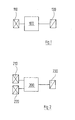
- This one shown circuit arrangement can be operated any sanitary fitting, such as a Basin tap, urinal or shower be used. It includes a capacitive sensor 110, an evaluation circuit 100 and a driver circuit 130, with which at least one a water flow controlling solenoid valve can be energized.
- the evaluation circuit 100 includes a programmable Processor as well as a memory in which different Operating modes and operating parameters are stored, in which the circuit can be operated.
- Mode here is a particular sequence understood of transactions that are settled when the capacitive sensor 110 the presence of a user determines and trigger a stream of water. at these processes can be waiting times, flushing times or flushing act.
- Operating Parameters are Variables such as the duration of waiting times, rinsing pulses, Values of temperatures, flow rates per unit time or the like understood.
- the evaluation circuit 100 can be in two different Operating modes work: In "normal mode” it recognizes in the presence more fully described below an output signal of the capacitive sensor 110, checks if this is a specific, the Change of operating mode triggering code is triggered, if not, according to each active program the solenoid valve 130 turns off and, if the output signal of the capacitive sensor 110 as corresponding code has been understood, in one "Programming mode" to.
- "normal mode” it recognizes in the presence more fully described below an output signal of the capacitive sensor 110, checks if this is a specific, the Change of operating mode triggering code is triggered, if not, according to each active program the solenoid valve 130 turns off and, if the output signal of the capacitive sensor 110 as corresponding code has been understood, in one "Programming mode" to.
- evaluation circuit 100 If the evaluation circuit 100 is operated in programming mode, in this case they willingly become capacitive Sensor 110 also generated signals detailed manner below for choosing a new program, so if necessary to select a different mode or other operating parameters.
- Figure 3 is a flow chart representing the different processes.
- step 1 a pulse, so an output signal occurs of the capacitive sensor 110, and is the evaluation circuit 100 supplied. Depending on whether this yourself in normal mode or in programming mode, happens the finishing different.
- the evaluation circuit 100 is in the Normal mode is.
- the program progresses in this Trap to program step 3 on. In this will be within a certain time window checked for a given time Number n, for example 4, inputs pulses.
- the Number n is chosen so that normally the occurrence so many impulses in the window in question is not It is probable, then, that the occurrence of these impulses as a sign of a voluntary operation of the capacitive Sensors 110 may be understood. Will be within the time window does not reach the number n, that works Program to program step 4 and triggers after currently active program, the driver circuit 130, what a corresponding stream of water from the sanitary fitting leads.
- step 3 within the given Time window the number n of pulses of the capacitive
- the program of the evaluation circuit changes 100 to step 5.
- step 5 becomes kept a certain waiting time in which checked will, if another pulse is received. Is this the Case, the acquired pulse train will not be as a result a voluntary operation of the capacitive sensor 110 but counted as random. So kick inside the first waiting time in step 5, another impulse, the program changes from step 5 to step 4, in which in the above already described manner, the driver circuit 130 is put into operation.
- step 6 a second waiting period initiated.
- a Acknowledgment signal generated for example in the form that the solenoid valve or valves during the second waiting time be opened.
- the second waiting time will be again checked if another impulse occurs. Is this the Case, this will be similar to step 5 as unintentional Actuation of the capacitive sensor 110 understood; by switching to step 4 triggers the evaluation circuit 100, the function of the driver circuit 130 from.
- a third waiting period is started (step 7). This, too, essentially serves as security to obtain that the detected pulse train in fact the consequence of a voluntary activity of the capacitive sensor 110 is with which the change to the programming mode is intended. This user's desire must be within the third Waiting time by another impulse, so another willful approach to the capacitive sensor 110, be confirmed. Kicks in the third waiting time no such acknowledgment pulse changes Program from step 7 to step 8, so returns to the Normal mode back.
- the evaluation circuit 100 goes into the programming mode above.
- step 2 now the presence of the programming mode detected.
- the program goes to the step 10, in which the number of pulses now input is determined.
- the program waits in step 11 a certain time to ensure that the User entered the full number of desired pulses Has. Will be within the waiting time of the step 11 received another pulse, the waiting time go through step 11 again.
- the further impulse is Number of detected pulses with different numbers compared, in the memory of the evaluation circuit 100th are stored. Each of these numbers stands for one certain mode or for a particular value of a Operating parameters, with or the sanitary fitting should be operated.
- step 14 Detects the evaluation circuit 100 that the detected Number of pulses with one stored in memory Number matches, in step 14, the corresponding Program retrieved.
- step 15 a the positive completion of the programming process indicating Acknowledgment signal generated. This can be it again around a continuous flow of water for a certain time act. Now the program returns to normal mode (Step 16), but now in the new Operating mode or the new value of the operating parameter is operated.
- Step 13 Detects the evaluation circuit 100 in step 12, the detected Number of impulses not as one of them in her stored numbers, so an error signal is generated (Step 13) and the program returns to Step 16 in FIG Normal mode back, but in the previous one active mode or with the previously active values of the Operating parameters.
- the illustrated in Figure 2 embodiment of a Circuitry with which also the most diverse Sanitary fittings in different operating modes and with different values of the operating parameters can be operated, secures against an unintentional change to the programming mode in hardware more elaborate, as well something safe way off.
- the circuit arrangement of Figure 2 includes a capacitive sensor 210, which corresponds to the sensor 110 of Figure 1 and the triggering the water flow is used.
- a second Capacitive sensor 220 is provided on a appropriate place that he is in the normal Use of the sanitary fitting not unintentionally responds. To the capacitive sensor 220 so for dispensing to bring an output signal is a conscious Approach required.
- the output signals of both capacitive sensors 210, 220 are fed to an evaluation circuit 200, the in the same way as the evaluation circuit 100 is a programmable Processor and a memory contains. In the latter are again, coded by a certain number, different operating modes and different values stored various operating parameters.
- the evaluation circuit 200 again controls a driver circuit 230 at which one or more solenoid valves energized.
- step 301 the occurrence of an output signal of serving for triggering the water flow capacitive sensor 210 represents.
- step 302 is again differentiated, in which operating mode the evaluation circuit 200 is currently located. First Let us assume that this is the normal mode is. Similar to step 3 of FIG Embodiment is also in the in FIG 4, counted in step 303, how many pulses within a certain time window occur.
- the Code for the transition to the programming mode is used, so the program triggers the energization of the driver circuit 230 in step 304. If, on the other hand, it is found that within the time window n pulses are received goes the program into a waiting time (step 305). Becomes now within this waiting time the second capacitive Sensor 220 by deliberate approximation of a body part actuated, an acknowledgment signal occurs.
- the circuit acknowledges in step 306, the understood command. This receipt can again by briefly opening the or the solenoid valves of the sanitary fitting consist.
- the driver circuit is only activated, if the received pulse train does not follow the pulse train code enstpricht. It may, however, be cheap be, even if the received pulse train as Pulse sequence code is detected, a triggering of the driver circuit bring about. Such a trigger remains in this case only off, if the evaluation circuit already in programming mode.
Landscapes
- Geophysics And Detection Of Objects (AREA)
- Domestic Plumbing Installations (AREA)
- Sanitary Device For Flush Toilet (AREA)
- Electronic Switches (AREA)
Applications Claiming Priority (2)
| Application Number | Priority Date | Filing Date | Title |
|---|---|---|---|
| DE200410027948 DE102004027948C5 (de) | 2004-06-08 | 2004-06-08 | Sanitärarmatur mit einer Schaltungsanordnung |
| DE102004027948 | 2004-06-08 |
Publications (2)
| Publication Number | Publication Date |
|---|---|
| EP1605593A2 true EP1605593A2 (fr) | 2005-12-14 |
| EP1605593A3 EP1605593A3 (fr) | 2011-03-16 |
Family
ID=34937211
Family Applications (1)
| Application Number | Title | Priority Date | Filing Date |
|---|---|---|---|
| EP05011996A Withdrawn EP1605593A3 (fr) | 2004-06-08 | 2005-06-03 | Circuit de commande d'une armature sanitaire |
Country Status (2)
| Country | Link |
|---|---|
| EP (1) | EP1605593A3 (fr) |
| DE (1) | DE102004027948C5 (fr) |
Cited By (2)
| Publication number | Priority date | Publication date | Assignee | Title |
|---|---|---|---|---|
| DE102013208999A1 (de) | 2013-05-15 | 2014-11-20 | EDISEN SENSOR SYSTEME GmbH & Co. KG | Verfahren und Vorrichtung für ein kapazitives berührungsloses Eingabesystem auf Basis einer einzigen Sensorfläche |
| US9657471B2 (en) | 2012-11-02 | 2017-05-23 | Kohler Co. | Touchless flushing systems and methods |
Citations (2)
| Publication number | Priority date | Publication date | Assignee | Title |
|---|---|---|---|---|
| DE19508644A1 (de) | 1995-03-10 | 1996-09-12 | Harald Schrott | Wasserauslaufarmatur |
| EP0940507A2 (fr) | 1998-03-02 | 1999-09-08 | Friedrich Grohe Aktiengesellschaft | ContrÔle de robinetterie d'eau |
Family Cites Families (13)
| Publication number | Priority date | Publication date | Assignee | Title |
|---|---|---|---|---|
| US3805096A (en) * | 1973-01-22 | 1974-04-16 | W Hamilton | Coded touch multifunction touch control switch circuitry |
| DE7523892U (de) * | 1975-07-26 | 1976-04-29 | Dalferth, Gotthilf Robert, 7141 Poppenweiler | Vorrichtung zur abgabe von fluessigkeiten ueber einen auslauf |
| DE2629794A1 (de) * | 1976-07-02 | 1978-01-05 | Hansa Metallwerke Ag | Kapazitiv betaetigbare waschtisch- mischarmatur fuer kalt- und warmwasser |
| US4420811A (en) * | 1980-03-03 | 1983-12-13 | Price-Pfister Brass Mfg. Co. | Water temperature and flow rate selection display and control system and method |
| DE4106539C2 (de) * | 1991-03-01 | 1994-12-15 | Hansa Metallwerke Ag | Einrichtung zur berührungslosen Steuerung einer Dusche |
| DE9201341U1 (de) * | 1992-02-04 | 1992-03-26 | Schmidt, Hans-Peter, 7888 Rheinfelden | Einheit zur Umrüstung handelsüblicher Sanitärarmaturen und Einlochmischbatterien auf berührungslos gesteuerte Wasserzufuhrunterbrechung |
| DE19625252A1 (de) * | 1996-06-25 | 1998-01-02 | Brand Gerhart Rosemarie | Wasserauslauf mit manueller und automatischer Bedienung |
| DE29620414U1 (de) * | 1996-11-22 | 1997-01-16 | Kludi-Armaturen Paul Scheffer KG, 58730 Fröndenberg | Vorrichtung zur wiederholbaren Dosierung von Fluids |
| DE19917091C1 (de) * | 1999-04-15 | 2000-06-29 | Hermann Kovacs | Vorrichtung zur Einstellung der Helligkeit eines Leuchtmittels, bei welcher durch den Benutzer wählbar sowohl sprunghaftes als auch stetiges Dimmen möglich ist |
| DE10025760B4 (de) * | 2000-05-25 | 2005-11-24 | Knapp Logistik Automation Ges.M.B.H. | Stauförderbahn mit programmierbarer Sensoreinheit |
| DE10156771A1 (de) * | 2001-11-19 | 2003-05-28 | Bsh Bosch Siemens Hausgeraete | Elektrisches Haushaltsgerät |
| EP1466118A4 (fr) * | 2001-12-26 | 2008-11-12 | Arichell Tech Inc | Dispositifs de chasse d'eau equipes de nouveaux capteurs et regulateurs |
| EP1497581A4 (fr) * | 2002-04-10 | 2008-12-31 | Arichell Tech Inc | Dispositifs de chasse d'eau pour reservoirs a soupapes et distributeurs nouveaux |
-
2004
- 2004-06-08 DE DE200410027948 patent/DE102004027948C5/de not_active Expired - Fee Related
-
2005
- 2005-06-03 EP EP05011996A patent/EP1605593A3/fr not_active Withdrawn
Patent Citations (2)
| Publication number | Priority date | Publication date | Assignee | Title |
|---|---|---|---|---|
| DE19508644A1 (de) | 1995-03-10 | 1996-09-12 | Harald Schrott | Wasserauslaufarmatur |
| EP0940507A2 (fr) | 1998-03-02 | 1999-09-08 | Friedrich Grohe Aktiengesellschaft | ContrÔle de robinetterie d'eau |
Cited By (6)
| Publication number | Priority date | Publication date | Assignee | Title |
|---|---|---|---|---|
| US9657471B2 (en) | 2012-11-02 | 2017-05-23 | Kohler Co. | Touchless flushing systems and methods |
| US10851532B2 (en) | 2012-11-02 | 2020-12-01 | Kohler Co. | Touchless flushing systems and methods |
| US11560702B2 (en) | 2012-11-02 | 2023-01-24 | Kohler Co. | Touchless flushing systems and methods |
| US12098534B2 (en) | 2012-11-02 | 2024-09-24 | Kohler Co. | Touchless flushing systems and methods |
| DE102013208999A1 (de) | 2013-05-15 | 2014-11-20 | EDISEN SENSOR SYSTEME GmbH & Co. KG | Verfahren und Vorrichtung für ein kapazitives berührungsloses Eingabesystem auf Basis einer einzigen Sensorfläche |
| DE102013208999B4 (de) * | 2013-05-15 | 2015-11-12 | EDISEN SENSOR SYSTEME GmbH & Co. KG | Verfahren und Vorrichtung für ein kapazitives berührungsloses Eingabesystem auf Basis einer einzigen Sensorfläche |
Also Published As
| Publication number | Publication date |
|---|---|
| DE102004027948A1 (de) | 2006-01-05 |
| DE102004027948C5 (de) | 2010-01-28 |
| DE102004027948B4 (de) | 2008-06-19 |
| EP1605593A3 (fr) | 2011-03-16 |
Similar Documents
| Publication | Publication Date | Title |
|---|---|---|
| EP0722019B1 (fr) | Commande de douche automatique | |
| EP2001331B1 (fr) | Dispositif pour agir sur le mouvement de pièces de meubles mobiles les unes par rapport aux autres, et meuble correspondant | |
| EP0501262B1 (fr) | Robinetterie commandée à proximité | |
| DE69221859T2 (de) | Sicherheitsvorrichtung für einen Garagentorantrieb | |
| DE69709967T2 (de) | Vorrichtung zum Steuern einer Gruppe von Badezimmergeräten | |
| DE69320549T2 (de) | Toilettengarnitur | |
| DE69806032T2 (de) | Wasserarmatur mit berührungsloser steuerung | |
| EP2586959B1 (fr) | Dispositif de sécurisation, dispositif de fermeture et unité d'évaluation | |
| EP0910712B1 (fr) | Element de robinetterie pour l'ecoulement d'eau | |
| DE3885861T2 (de) | Elektrische Vorrichtung zum Öffnen und Schliessen eines Wasserhahnes. | |
| DE69015973T2 (de) | Verfahren und Vorrichtung zum Verstellen einer Verdunkelungsanordnung in justierbaren Positionen und Installation zur Durchführung der Anmeldung. | |
| DE102004018453A1 (de) | Barrierenbewegungsbetätiger einschliesslich Schliesszeitgebermerkmal | |
| DE102004039917B4 (de) | Betätigungsvorrichtung für Armaturen und ein Verfahren zum Betreiben einer solchen | |
| DE29707448U1 (de) | Garagentüröffner mit Lichtsteuerung | |
| DE29707462U1 (de) | Mehrere Codeformate in einem einzigen Garagentüröffner mit zumindest einem Festcodeformat und zumindest einem Rollcodeformat | |
| EP0501263B1 (fr) | Dispositif pour la télécommande d'une douche | |
| DE3630003A1 (de) | Motorbetaetigtes fenster | |
| EP1336691A1 (fr) | Robinetterie sanitaire de proximite | |
| DE2902683A1 (de) | Steuerschaltung fuer fahrzeugfenster- betaetigungsvorrichtungen | |
| EP3144436A1 (fr) | Procede et systeme de fonctionnement d'un dispositif sanitaire | |
| EP0859298B1 (fr) | Commande de porte | |
| EP2514658A2 (fr) | Système de verrouillage | |
| EP1605593A2 (fr) | Circuit de commande d'une armature sanitaire | |
| EP2578758B1 (fr) | Procédé de réglage de paramètres et dispositif utilisé pour ce procédé | |
| DE4218798A1 (de) | Schließanlage für Verschlüsse eines Fahrzeuges |
Legal Events
| Date | Code | Title | Description |
|---|---|---|---|
| PUAI | Public reference made under article 153(3) epc to a published international application that has entered the european phase |
Free format text: ORIGINAL CODE: 0009012 |
|
| AK | Designated contracting states |
Kind code of ref document: A2 Designated state(s): AT BE BG CH CY CZ DE DK EE ES FI FR GB GR HU IE IS IT LI LT LU MC NL PL PT RO SE SI SK TR |
|
| AX | Request for extension of the european patent |
Extension state: AL BA HR LV MK YU |
|
| PUAL | Search report despatched |
Free format text: ORIGINAL CODE: 0009013 |
|
| REG | Reference to a national code |
Ref country code: DE Ref legal event code: R079 Free format text: PREVIOUS MAIN CLASS: H03K0017955000 Ipc: E03C0001050000 |
|
| AK | Designated contracting states |
Kind code of ref document: A3 Designated state(s): AT BE BG CH CY CZ DE DK EE ES FI FR GB GR HU IE IS IT LI LT LU MC NL PL PT RO SE SI SK TR |
|
| AX | Request for extension of the european patent |
Extension state: AL BA HR LV MK YU |
|
| RIC1 | Information provided on ipc code assigned before grant |
Ipc: H03K 17/955 20060101ALI20110208BHEP Ipc: E03C 1/05 20060101AFI20110208BHEP |
|
| RIN1 | Information on inventor provided before grant (corrected) |
Inventor name: KUNKEL, HORST |
|
| 17P | Request for examination filed |
Effective date: 20110823 |
|
| AKX | Designation fees paid |
Designated state(s): AT CH DE LI |
|
| RBV | Designated contracting states (corrected) |
Designated state(s): AT CH DE LI |
|
| 17Q | First examination report despatched |
Effective date: 20120330 |
|
| RAP1 | Party data changed (applicant data changed or rights of an application transferred) |
Owner name: HANSA ARMATUREN GMBH |
|
| GRAP | Despatch of communication of intention to grant a patent |
Free format text: ORIGINAL CODE: EPIDOSNIGR1 |
|
| STAA | Information on the status of an ep patent application or granted ep patent |
Free format text: STATUS: GRANT OF PATENT IS INTENDED |
|
| INTG | Intention to grant announced |
Effective date: 20180518 |
|
| RIC1 | Information provided on ipc code assigned before grant |
Ipc: E03C 1/05 20060101AFI20110208BHEP Ipc: H03K 17/955 20060101ALI20110208BHEP |
|
| STAA | Information on the status of an ep patent application or granted ep patent |
Free format text: STATUS: THE APPLICATION IS DEEMED TO BE WITHDRAWN |
|
| 18D | Application deemed to be withdrawn |
Effective date: 20180929 |