EP1605655A2 - Leistungsreduzierung im Aufwärtskanal - Google Patents
Leistungsreduzierung im Aufwärtskanal Download PDFInfo
- Publication number
- EP1605655A2 EP1605655A2 EP05011273A EP05011273A EP1605655A2 EP 1605655 A2 EP1605655 A2 EP 1605655A2 EP 05011273 A EP05011273 A EP 05011273A EP 05011273 A EP05011273 A EP 05011273A EP 1605655 A2 EP1605655 A2 EP 1605655A2
- Authority
- EP
- European Patent Office
- Prior art keywords
- power
- transceiver
- upstream
- signal
- bit
- Prior art date
- Legal status (The legal status is an assumption and is not a legal conclusion. Google has not performed a legal analysis and makes no representation as to the accuracy of the status listed.)
- Withdrawn
Links
Images
Classifications
-
- H—ELECTRICITY
- H04—ELECTRIC COMMUNICATION TECHNIQUE
- H04L—TRANSMISSION OF DIGITAL INFORMATION, e.g. TELEGRAPHIC COMMUNICATION
- H04L27/00—Modulated-carrier systems
- H04L27/26—Systems using multi-frequency codes
- H04L27/2601—Multicarrier modulation systems
- H04L27/2614—Peak power aspects
-
- H—ELECTRICITY
- H04—ELECTRIC COMMUNICATION TECHNIQUE
- H04B—TRANSMISSION
- H04B3/00—Line transmission systems
- H04B3/02—Details
- H04B3/32—Reducing cross-talk, e.g. by compensating
Definitions
- the present invention relates generally to Asymmetrical Digital Subscriber Line (ADSL) communication systems. More specifically, the present invention relates to determining the power level for the upstream direction in an ADSL communication system.
- ADSL Asymmetrical Digital Subscriber Line
- Broadband communication networks are used in a variety of high speed application services such as internet access, video conferencing, video on demand, and interactive TV.
- fiber optic cable is the preferred transmission media for such high data rate services
- the lack of fiber optic cables in existing networks and the prohibitive costs of installing such optical networks have led telephone companies around the world to include existing twisted-pair loops in their next generation broadband access networks. Because current telephone wiring connections were not designed to support high speed data communications, technologies were developed to increase the transmission capabilities of existing telephone wiring.
- ADSL Asymmetrical Digital Subscriber Line
- DMT modulation divides the available bandwidth of communications channels into multiple carriers, also referred to as bins or sub-channels, and employs the multiple carriers for both upstream and downstream communication.
- Each carrier is allocated a number of bits to send with each transmission.
- Frequency-division-multiplexing is often used, where upstream and downstream communication use carriers in different frequency bands.
- DMT modulation maximizes the available channel capacity by using a large number of carriers rather than a single carrier, and thereby optimizes performance of the transmission.
- G.992.3 published by the International Telecommunication Union (ITU) (also referred to as ADSL2 or G.992.3 standard), which is incorporated herein by reference, provides an upstream power backoff procedure by introducing a maximum received power parameter: MAXRXPWR.
- MAXRXPWR This parameter defines the maximum power that the Central Office Equipment (hereinafter "CO") should receive from the Customer Premise Equipment (hereinafter "CPE").
- CO Central Office Equipment
- CPE Customer Premise Equipment
- the CO measures its received signal power and computes the amount of power backoff that should be applied on the upstream signal.
- This backoff value is communicated to the CPE during this same phase of the initialization sequence in the C-MSG-PCB message.
- the solution in G.992.3 ensures that the configured maximum receive power will never be exceeded.
- the desirable result is the reduction of the effect of signal crosstalk in the loop plant.
- the present invention comprises a system and method, e.g., a Central Office line card and a method for training a central office modem, substantially as shown in and/or described in connection with at least one of the figures, as set forth more completely in the claims.
- a method for optimizing the upstream signal power level in a communication system comprising a first transceiver for receiving and processing an input communications signal from a second transceiver is provided, the method comprising:
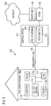
- the communications system 100 enables voice communications, video, and data services to be exchanged based on bi-directional transfer of Internet Protocol (IP) or Asynchronous Transfer Mode (ATM) traffic between a customer premise 102 and a central office 104 via a subscriber line 106.
- IP Internet Protocol
- ATM Asynchronous Transfer Mode
- the customer premise end 102 supports various customer premise devices which may be coupled to the subscriber line 106.
- devices such as telephones 110a, 110b, a fax machine 112, a xDSL CPE (Customer Premise Equipment) modem 114 and the like may all be coupled to the subscriber line 106.
- a personal computer 116 may be connected via xDSL CPE modem 114.
- various central office equipment may be coupled to the subscriber line 106, such as a xDSL CO (Central Office) modem 120 and a POTS switch 122.
- XDSL CO modem 120 may be further coupled to a router or ISP 124 which allows access to the Internet 126.
- POTS switch 122 may be further coupled to a PSTN 128.
- the subscriber line106 provides for the high-speed, reliable, and secure transport of data between the CO xDSL modem 120 and the remote xDSL CPE modem 114.
- the subscriber line 106 may comprise twisted-pair copper telephone lines, coaxial cable, fiber optic cable, or a combination of coaxial cable and fiber optic cable linked via one or more fiber nodes.
- the CO xDSL modem 120 is typically found within a telephone company's central office, and the remote xDSL CPE modem is found within individual homes and businesses.
- the communications system 100 of Figure 1 only one remote xDSL CPE modems 114 is shown. In general, the communications system 100 may include any number and type of central or remote xDSL modems.
- the modems 114, 120 may transmit and receive data pursuant to various telecommunications standards such as the ADSL1 ITU G.992.1 and G992.2 standards.
- system 100 provides for data to be sent in each direction between the CO xDSL modem 120 and the xDSL CPE modem 114.
- the remote xDSL modem 114 operates as an interface between the subscriber line 106 and at least one attached user device.
- the remote CPE xDSL modem 114 performs the functions necessary to convert downstream signals received over the subscriber line 106 into IP or ATM data packets for receipt by an attached user device.
- Downstream refers to the direction of transmission from a telephone company's central office to a remote location such as a home or business. Additionally, the remote xDSL CPE modem 114 performs the functions necessary to convert IP or ATM data packets received from the attached user devices such as 116 into upstream burst signals suitable for transfer over the subscriber line 106. Upstream refers to the direction of transmission from a remote business or home to a telephone company's central office. Data other than IP or ATM packets may as well be carried over the communications system 100.
- the CO modem 120 receives a maximum received power configuration parameter (MAXRXPWR) from an operator for the system.
- MAXRXPWR maximum received power configuration parameter
- a CO modem may use a preselected default value for MAXRXPWR constraint.
- the CO modem 120 measures the received power signal from the CPE modem 114 and compares it to the maximum received power configuration parameter.
- the CO modem uses the received power signal and the selected MAXRXPWR constraint to compute the appropriate power backoff required to achieve the optimal upstream power level.
- the CO modem 120 then adjusts the bit and gain allocation tables to ensure that the appropriate power backoff will be achieved by the CPE modem 114.
- the bit and gain allocation tables are computed in such a way that: 1) the achieved bit rate is optimized within the operator constrains; 2) the noise margin is well equalized amongst the different sub-carriers used; and 3) the noise margin doesn't exceed the configured maximum noise margin.
- This third constraint is typically achieved by requesting low gain values to the CPE, thereby lowering the CPE transmit power.
- the CO modem 120 then sends the bit and gain allocation tables to the CPE modem 114.
- the CPE modem 114 uses the modified bit and gain allocation tables to configure its transmit path and optimize the upstream power level of its signal.
- DSL CO modem 120 incorporates a BCM6411 or BCM6510 device, produced by Broadcom Corporation of Irvine, California, to implement its various functions.
- the present invention allows the CO modem 120 to indirectly control the CPE transmitted power.
- a CPE modem 114 operating in accordance with the ADSL1 standard is no longer restricted to using the same nominal upstream transmit power,
- the present invention ensures that the selected maximum received power constraint for the CO modem will never be exceeded resulting in the reduction of the effect of signal crosstalk in the loop plant.
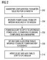
- the CO modem first receives a maximum received power (MAXRXPWR) configuration parameter for the CO modem.
- the MAXRXPWR parameter defines the maximum power that the CO modem should receive from the CPE modem.
- the value of MAXRXPWR may either be an operator configuration, for example, as part of a multi-standard line profile, or it may be a previously chosen default value.
- the CO modem measures the received power signal from the CPE modem.
- the CO modem then uses the received power signal to compute, at step 206, the amount of power backoff that needs to be applied by the CPE modem transmitter to ensure that the received power at the CO meets this maximum received power constraint.
- the bit and gain allocation tables are then modified at step 208 to ensure that this power backoff is achieved.
- the modified bit and gain allocation tables are then sent to the CPE modem which uses the tables to configure its transmit path and optimize the upstream power level of its signal.
- the present invention provides a maximum received power constraint in systems operating according to the ADSL1 standard. This maximum received power constraint is then used to determine a power backoff which is used in turn in the derivation of the bit and gain tables used in ADSL1 systems to optimize the upstream power level.
- the signal-to-noise ratio (SNR) that results from applying the power backoff of the present invention in an ADSL1 compliant device cannot be directly measured. Indeed, there is no provision in the ADSL1 standard to offer a specific known signal in which the transmit power is reduced that can be used by the receiver to measure the resulting SNR.
- the present invention overcomes this inability to directly measure the SNR that results from applying the power backoff by estimating the SNR.
- the MAXRXPWR configuration parameter enables the CO modem to compute a gain table (i.e. an individual gain per DMT carrier) that achieves a certain power backoff. The use of the lower gain values may negatively impact the SNR available on the DMT carriers on which this gain is applied.
- This lower SNR may limit the constellation size, and hence the number of bits that can be placed on that carrier.
- the step of the present invention of estimating accurately the SNR resulting from the lower gains aims at maximizing the number of bits that can be used in order to achieve the best possible rate despite the lower upstream power used.
- an extra backoff constraint is included by assuming that the lower gains used will lead to a proportionally lower SNR at the receiver. Based on this assumption, the bit and gain allocation tables can be readily computed and the maximum power constraint will be easily met.
- noise sources are distinguished.
- the SNR in the upstream direction is not significantly influenced by the absolute signal power.
- the dominant noise sources in those conditions are actually directly related to the actual received signal power.
- ADC Analog to Digital Converter
- LNA Low Noise Amplifier
- LNA Low Noise Amplifier
- Inter-Symbol Interference "noise” scales linearly with the received signal power.
- the present invention may distinguish noise in REVERB versus noise in Medley and distinguish noise from distorsion.
- the present invention may also distinguish noise in simplex (US only / DS only) versus noise in duplex and distinguish echo noise from Rx noise.
- the present invention may distinguish noise with higher/lower AGC setting and distinguish LNA noise from ADC noise.
- the present invention accurately computes the SNR loss that will result from a decrease in upstream signal transmit power, even if this resulting SNR cannot be effectively measured.
- the SNR will in most cases be completely dominated by internal noise.
- An accurate SNR prediction may lead to a resulting SNR that is easily 6 dB better than the simple conservative prediction. This in turn translates into an upstream rate improvement of approximately 200kb/s.
Landscapes
- Engineering & Computer Science (AREA)
- Computer Networks & Wireless Communication (AREA)
- Signal Processing (AREA)
- Telephonic Communication Services (AREA)
- Cable Transmission Systems, Equalization Of Radio And Reduction Of Echo (AREA)
Applications Claiming Priority (2)
| Application Number | Priority Date | Filing Date | Title |
|---|---|---|---|
| US57721404P | 2004-06-07 | 2004-06-07 | |
| US577214P | 2004-06-07 |
Publications (2)
| Publication Number | Publication Date |
|---|---|
| EP1605655A2 true EP1605655A2 (de) | 2005-12-14 |
| EP1605655A3 EP1605655A3 (de) | 2008-02-27 |
Family
ID=34979200
Family Applications (1)
| Application Number | Title | Priority Date | Filing Date |
|---|---|---|---|
| EP05011273A Withdrawn EP1605655A3 (de) | 2004-06-07 | 2005-05-24 | Leistungsreduzierung im Aufwärtskanal |
Country Status (4)
| Country | Link |
|---|---|
| US (1) | US7778346B2 (de) |
| EP (1) | EP1605655A3 (de) |
| CN (1) | CN1716989B (de) |
| TW (1) | TWI347757B (de) |
Cited By (1)
| Publication number | Priority date | Publication date | Assignee | Title |
|---|---|---|---|---|
| EP2369781A1 (de) * | 2010-03-19 | 2011-09-28 | Alcatel Lucent | Garantierte Dienstgüte in Modus mit niedrigem Stromverbrauch |
Families Citing this family (12)
| Publication number | Priority date | Publication date | Assignee | Title |
|---|---|---|---|---|
| US7668232B2 (en) * | 2005-07-08 | 2010-02-23 | Texas Instruments Incorporated | System and method to determine power cutback in communication systems |
| US7936778B2 (en) * | 2005-09-30 | 2011-05-03 | Broadcom Corporation | Method and system for 10GBASE-T start-up |
| CN101030997B (zh) | 2006-03-03 | 2011-01-12 | 华为技术有限公司 | 一种获取串扰信息的方法及装置 |
| CN101056342B (zh) | 2006-04-13 | 2011-04-20 | 华为技术有限公司 | 一种在数字用户线技术中进行通信的方法和装置 |
| US7881403B2 (en) | 2006-10-10 | 2011-02-01 | Futurewei Technologies, Inc. | System for realizing emergency rate adjustment |
| US8009749B2 (en) * | 2007-12-04 | 2011-08-30 | Lantiq Deutschland Gmbh | Method of transmission power control and communication device |
| CN101729094B (zh) * | 2008-10-31 | 2013-04-17 | 华为技术有限公司 | 数字用户线中上行功率下调方法、装置及系统 |
| US8204100B2 (en) * | 2009-01-15 | 2012-06-19 | Lantiq Deutschland Gmbh | Methods and apparatuses for data transmission |
| JP5565082B2 (ja) * | 2009-07-31 | 2014-08-06 | ソニー株式会社 | 送信電力決定方法、通信装置及びプログラム |
| US8817857B2 (en) | 2010-07-28 | 2014-08-26 | Ikanos Communications, Inc. | UPBO for vectored DSL |
| EP2736242B1 (de) * | 2012-11-22 | 2019-03-06 | Lantiq Beteiligungs-GmbH & Co.KG | Optimierung des Stromverbrauchs in einem Kommunikationssystem |
| US11700581B2 (en) * | 2019-05-03 | 2023-07-11 | Hughes Network Systems, Llc | Transmit frequency based terminal uplink power control in a satellite communication system |
Family Cites Families (15)
| Publication number | Priority date | Publication date | Assignee | Title |
|---|---|---|---|---|
| US5321849A (en) * | 1991-05-22 | 1994-06-14 | Southwestern Bell Technology Resources, Inc. | System for controlling signal level at both ends of a transmission link based on a detected valve |
| US5784410A (en) * | 1996-06-03 | 1998-07-21 | Matsushita Electric Industrial Co., Ltd. | Reception automatic gain control system and method |
| US6215793B1 (en) * | 1996-11-12 | 2001-04-10 | Alcatel | Initialization protocol for adaptive data rates, and related transceiver |
| JPH11313043A (ja) * | 1998-02-27 | 1999-11-09 | Nec Corp | マルチキャリア伝送システム及び伝送装置並びに伝送方法 |
| US6356585B1 (en) * | 1998-09-29 | 2002-03-12 | Conexant Systems, Inc. | Power cutback in splitterless ADSL systems |
| GB9823396D0 (en) * | 1998-10-27 | 1998-12-23 | Roke Manor Research | Method of and apparatus for power control |
| US6829307B1 (en) * | 1999-02-24 | 2004-12-07 | The Board Of Trustees Of Leland Stanford Junior University | Express bit swapping in a multicarrier transmission system |
| US6711207B1 (en) * | 1999-03-11 | 2004-03-23 | Globespanvirata, Inc. | System and method for reduced power consumption in digital subscriber line modems |
| KR100304666B1 (ko) * | 1999-08-28 | 2001-11-01 | 윤종용 | 음성 향상 방법 |
| US6487241B1 (en) * | 1999-11-22 | 2002-11-26 | Advanced Micro Devices, Inc. | Method and apparatus employing cutback probe |
| US6721394B1 (en) * | 1999-12-09 | 2004-04-13 | 3Com Corporation | Method for reducing noise from an asymmetric digital subscriber line modem |
| CA2323164A1 (en) * | 2000-10-11 | 2002-04-11 | Ramesh Mantha | Method, system and apparatus for improving reception in multiple access communication systems |
| KR100456693B1 (ko) * | 2002-03-28 | 2004-11-10 | 삼성전자주식회사 | 다중채널 통신 시스템의 비트 할당을 최적화하여 셋업시간을 최소화하는 방법 |
| FI115879B (fi) * | 2003-03-07 | 2005-07-29 | Nokia Corp | Kanavan valinta langattomassa tietoliikennejärjestelmässä |
| US6952519B2 (en) * | 2003-05-02 | 2005-10-04 | Corning Incorporated | Large effective area high SBS threshold optical fiber |
-
2005
- 2005-05-24 EP EP05011273A patent/EP1605655A3/de not_active Withdrawn
- 2005-06-06 TW TW094118552A patent/TWI347757B/zh not_active IP Right Cessation
- 2005-06-06 CN CN2005100136498A patent/CN1716989B/zh not_active Expired - Fee Related
- 2005-06-07 US US11/146,097 patent/US7778346B2/en not_active Expired - Fee Related
Cited By (1)
| Publication number | Priority date | Publication date | Assignee | Title |
|---|---|---|---|---|
| EP2369781A1 (de) * | 2010-03-19 | 2011-09-28 | Alcatel Lucent | Garantierte Dienstgüte in Modus mit niedrigem Stromverbrauch |
Also Published As
| Publication number | Publication date |
|---|---|
| CN1716989A (zh) | 2006-01-04 |
| EP1605655A3 (de) | 2008-02-27 |
| TWI347757B (en) | 2011-08-21 |
| CN1716989B (zh) | 2011-06-22 |
| US20050271127A1 (en) | 2005-12-08 |
| US7778346B2 (en) | 2010-08-17 |
| TW200629756A (en) | 2006-08-16 |
Similar Documents
| Publication | Publication Date | Title |
|---|---|---|
| US9130654B2 (en) | Performance customization system and process for optimizing xDSL performance | |
| US6744811B1 (en) | Bandwidth management for DSL modem pool | |
| US6782082B2 (en) | Method and system for reducing cross-talk and avoiding bridged taps | |
| EP0969605A2 (de) | Reduktion von Übersprechen durch Formung des Sendesignals | |
| US7295621B2 (en) | Communication start-up with variant spectral density mask | |
| US20110019725A1 (en) | Dsl method having variable upload/download bit rate and application-specific dynamic profile switching | |
| US7778346B2 (en) | Upstream power cutback | |
| EP1231733A1 (de) | Verfahren zur Übertragungleistungsregelung in einer Teilnehmerleitung | |
| US20170118350A1 (en) | Resource allocation in a digital communication network | |
| EP1947831B1 (de) | Verfahren, system und vorrichtung zum justieren der sendeleistung des dsl-senders/-empfängers | |
| US6356585B1 (en) | Power cutback in splitterless ADSL systems | |
| US20060062288A1 (en) | Short loop ADSL power spectral density management | |
| US6553075B1 (en) | Method and apparatus for determining crosstalk | |
| US7536197B2 (en) | Apparatus and method of loop and rate dependent power cutback | |
| WO2000051303A1 (en) | Apparatus and method of tone allocation in digital subscriber line systems | |
| CN102165757A (zh) | 用于数据处理的方法和设备以及包含这种设备的通信系统 | |
| CN1832364B (zh) | 提高普通adsl信号传输距离的方法和数字用户线接入复用器 | |
| EP1328081B1 (de) | SNR basierte Bandbreitenverwaltung für einen DSL modempool | |
| JP2003516655A (ja) | 加入者モデムを用いて伝送データを伝送する方法 | |
| EP4604458A1 (de) | Vorrichtungen, systeme und verfahren zur übertragung von daten gemäss einem heimnetzwerkstandard über verdrillte kabelpaare | |
| EP1540871B1 (de) | Verfahren und anordnung zur einstellung der sendeleistung in einer digitalen teilnehmerleitung | |
| EP1998463A1 (de) | Verfahren und Vorrichtung zur Übersprechungsbeurteilung und eine solche Vorrichtung umfassendes Kommunikationssystem | |
| JP2001024736A (ja) | Tcm−isdnの下で動作するdslシステムのモデム用混合モード動作方法、モデムおよびコンピュータ使用可能な媒体 | |
| CA2436025A1 (en) | Apparatus and method of loop and rate dependent power cutback | |
| CA2354483A1 (en) | A method for loop and rate dependent power cutback |
Legal Events
| Date | Code | Title | Description |
|---|---|---|---|
| PUAI | Public reference made under article 153(3) epc to a published international application that has entered the european phase |
Free format text: ORIGINAL CODE: 0009012 |
|
| AK | Designated contracting states |
Kind code of ref document: A2 Designated state(s): AT BE BG CH CY CZ DE DK EE ES FI FR GB GR HU IE IS IT LI LT LU MC NL PL PT RO SE SI SK TR |
|
| AX | Request for extension of the european patent |
Extension state: AL BA HR LV MK YU |
|
| RAP1 | Party data changed (applicant data changed or rights of an application transferred) |
Owner name: BROADCOM CORPORATION |
|
| PUAL | Search report despatched |
Free format text: ORIGINAL CODE: 0009013 |
|
| AK | Designated contracting states |
Kind code of ref document: A3 Designated state(s): AT BE BG CH CY CZ DE DK EE ES FI FR GB GR HU IE IS IT LI LT LU MC NL PL PT RO SE SI SK TR |
|
| AX | Request for extension of the european patent |
Extension state: AL BA HR LV MK YU |
|
| 17P | Request for examination filed |
Effective date: 20080827 |
|
| AKX | Designation fees paid |
Designated state(s): DE FR GB |
|
| 17Q | First examination report despatched |
Effective date: 20081027 |
|
| STAA | Information on the status of an ep patent application or granted ep patent |
Free format text: STATUS: THE APPLICATION IS DEEMED TO BE WITHDRAWN |
|
| 18D | Application deemed to be withdrawn |
Effective date: 20131203 |