EP1605720A1 - Verfahren zur Zuweisung von Übertragungskanälen in einem Telekommunikationsnetz und Teilnehmerstation - Google Patents
Verfahren zur Zuweisung von Übertragungskanälen in einem Telekommunikationsnetz und Teilnehmerstation Download PDFInfo
- Publication number
- EP1605720A1 EP1605720A1 EP05019838A EP05019838A EP1605720A1 EP 1605720 A1 EP1605720 A1 EP 1605720A1 EP 05019838 A EP05019838 A EP 05019838A EP 05019838 A EP05019838 A EP 05019838A EP 1605720 A1 EP1605720 A1 EP 1605720A1
- Authority
- EP
- European Patent Office
- Prior art keywords
- transmission
- channel
- transmission channels
- base stations
- subscriber station
- Prior art date
- Legal status (The legal status is an assumption and is not a legal conclusion. Google has not performed a legal analysis and makes no representation as to the accuracy of the status listed.)
- Granted
Links
- 230000005540 biological transmission Effects 0.000 title claims abstract description 235
- 238000000034 method Methods 0.000 title claims description 26
- 238000005259 measurement Methods 0.000 claims description 50
- 230000008859 change Effects 0.000 claims description 16
- 230000008054 signal transmission Effects 0.000 claims description 7
- 238000010586 diagram Methods 0.000 description 5
- 230000008901 benefit Effects 0.000 description 3
- 150000001875 compounds Chemical class 0.000 description 3
- 238000011156 evaluation Methods 0.000 description 2
- 238000000926 separation method Methods 0.000 description 2
- 230000011664 signaling Effects 0.000 description 2
- 238000012546 transfer Methods 0.000 description 2
- OMBVEVHRIQULKW-DNQXCXABSA-M (3r,5r)-7-[3-(4-fluorophenyl)-8-oxo-7-phenyl-1-propan-2-yl-5,6-dihydro-4h-pyrrolo[2,3-c]azepin-2-yl]-3,5-dihydroxyheptanoate Chemical compound O=C1C=2N(C(C)C)C(CC[C@@H](O)C[C@@H](O)CC([O-])=O)=C(C=3C=CC(F)=CC=3)C=2CCCN1C1=CC=CC=C1 OMBVEVHRIQULKW-DNQXCXABSA-M 0.000 description 1
- 108010003272 Hyaluronate lyase Proteins 0.000 description 1
- 229940126540 compound 41 Drugs 0.000 description 1
- 230000007423 decrease Effects 0.000 description 1
- 230000001419 dependent effect Effects 0.000 description 1
- 238000011161 development Methods 0.000 description 1
- 230000018109 developmental process Effects 0.000 description 1
- 230000002452 interceptive effect Effects 0.000 description 1
- 238000010295 mobile communication Methods 0.000 description 1
- 238000012986 modification Methods 0.000 description 1
- 230000004048 modification Effects 0.000 description 1
- 230000008569 process Effects 0.000 description 1
- 230000007480 spreading Effects 0.000 description 1
Images

Classifications
-
- H—ELECTRICITY
- H04—ELECTRIC COMMUNICATION TECHNIQUE
- H04W—WIRELESS COMMUNICATION NETWORKS
- H04W16/00—Network planning, e.g. coverage or traffic planning tools; Network deployment, e.g. resource partitioning or cells structures
- H04W16/14—Spectrum sharing arrangements between different networks
- H04W16/16—Spectrum sharing arrangements between different networks for PBS [Private Base Station] arrangements
-
- H—ELECTRICITY
- H04—ELECTRIC COMMUNICATION TECHNIQUE
- H04W—WIRELESS COMMUNICATION NETWORKS
- H04W72/00—Local resource management
- H04W72/50—Allocation or scheduling criteria for wireless resources
- H04W72/54—Allocation or scheduling criteria for wireless resources based on quality criteria
- H04W72/542—Allocation or scheduling criteria for wireless resources based on quality criteria using measured or perceived quality
-
- H—ELECTRICITY
- H04—ELECTRIC COMMUNICATION TECHNIQUE
- H04W—WIRELESS COMMUNICATION NETWORKS
- H04W24/00—Supervisory, monitoring or testing arrangements
- H04W24/10—Scheduling measurement reports ; Arrangements for measurement reports
Definitions
- the invention is based on a method for the allocation of Transmission channels in a telecommunications network and of a subscriber station according to the type of independent Claims out.
- third-generation mobile systems for example according to the UMTS standard (Universal Mobile Telecommunication System) or the like, are for the transmission of Signals over an air interface between a Base station and a mobile station two concepts or modes depending on the used transmission resource intended.
- Frequency bands are different as transmission resource Frequency bands provided, it is an FDD mode (Frequency Division Duplex), in which for the uplink transmission direction from the mobile station to the base station and for the downlink transmission direction of the Base station to the mobile station two different Frequency bands are used to transmit the signals.
- time slots are selected as the transmission resource, then is the TDD (Time Division Duplex) mode for the uplink transmission direction and the downlink transmission direction when using the same Frequency band different time slots used become.
- TDD Time Division Duplex
- Another channel separation is for both modes by using a CDMA method (Code Division Multiple access) possible.
- the transmission channels for Connections between one or more base stations and Different mobile stations may be different Codes are separated from each other when using the same Transmission resource, for example, the same Time slot and / or the same frequency position.
- the code assignment for the set up Transmission channels coordinated by the mobile network so no Code is used multiple times.
- the inventive method for the allocation of Transmission channels in a telecommunications network and the inventive subscriber station with the features of independent claims have the advantage that in an uncoordinated operation of the base stations at least one of the transmission channels of the transmission of Signals between one of the base stations and one of the Mobile stations depending on a channel measurement, in the the transmission power at all possible Transmission channels is measured, then assigned, if the previously measured transmission power on this Transmission channel is minimal.
- the Possibility created the existing transmission channels optimal for the transmission of signals between set up the base stations and the mobile stations or distributed connections, so that the Capacity of the telecommunications network and thus the number the connections to be set up at the same time Telecommunications network increased, and even maximized can.
- One and the same transmission channel could even used simultaneously by different base stations if they are due to limited range influence each other only insignificantly or not at all.
- codes are provided, by the at least one transmission resource, in particular a time slot or a frequency band, with several of the transmission channels for transmitting signals spread between the base stations and the mobile stations and that the channel measurement comprises a code measurement the one received signal for each transmission resource with any approved code is despread to the Transmission power in each of the transmission channels measure up.
- a transmission resource for example a time slot or a frequency band of different at the same time Base stations can be shared.
- a Transmission resource such as a time slot or a frequency band, this way at the same time shared by multiple transmission channels. This distribution of transmission resources will make the Capacity of the telecommunications network and thus the number the connections to be set up at the same time Telecommunications network also increased.
- the channel measurement for the Assign at least one of the transmission channels between one of the base stations and one of the mobile stations a connection is made. In this way will increase the capacity of the telecommunications network for each set up at the earliest possible date used.
- the channel measurement for the Assignment of at least one of the transmission channels during an existing connection between one of the Base stations and one of the mobile stations performed will that parallel the connection quality of the existing Compound is measured and that falls below a predetermined value for the connection quality Channel change is performed and at least one new one Transmission channel depending on the channel measurement of the assigned to existing connection. This way you can a dynamic channel assignment for one or more existing connections are realized, so that all an existing connection just assigned Transmission channels the highest possible connection quality exhibit.
- Another advantage is that at least one of Transmission channels for use as a broadcast channel is reserved. In this way, the effort and the Time for the mobile stations to find the broadcast channel reduced, as they broadcast the channel from one already specified or preselected amount of Can locate transmission channels.
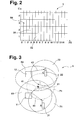
- FIG. 1 shows a block diagram of a 2 is a code time slot diagram
- FIG. 3 shows a first arrangement of FIG Base and mobile stations in a mobile network
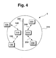
- Figure 4 a second arrangement of base and mobile stations in one Mobile network.
- 15 denotes a subscriber station of one Telecommunications network 5.
- the telecommunication network 5 can be used, for example, as a landline or as Mobile network be formed. Is this Telecommunications network 5 designed as a mobile network, so it may be at the subscriber station 15 to a Base station 11, 12 or a mobile station 21, 22 of the Telecommunications network 5 act according to Figure 3. in the The following is to be assumed by way of example that the Telecommunications network 5 as a mobile network and the Subscriber station 15 as a base station 11, 12 or as Mobile station 21, 22 are formed.
- the mobile radio system 5 and the subscriber station 15 can for example according to the GSM standard (Global System for Mobile Communications), according to the UMTS standard (Universal Mobile Telecommunication System) or the like.
- the subscriber station 15 shown in Figure 1 comprises a Receiving device 25 to which a receiving antenna 60th connected.
- the subscriber station 15 comprises according to Figure 1 also shows a transmitting device 35, to which a Transmit antenna 70 is connected.
- the receiving antenna 60 and the transmitting antenna 70 may also be, for example, by Using an antenna switch to a combined transmit / receive antenna be summarized.
- the Receiving device 25 is the output side with one hand an input of means 30 for code measurement and on the other hand with an input of a despreading device 45 connected.
- the means 30 for code measurement are also Codes of a first code memory 51 supplied. Of the Despreading device 45 is also at least one code a second code memory 52 is supplied.
- the means 30 for Code measurement are output side with an input of Means 10 connected to the channel measurement.
- the despreading device 45 is the output side with an input means 40 for measuring the quality of connection connected.
- An output of the means 40 for measuring the Connection quality is also the means 10th fed to the channel measurement.
- the means 10 for channel measurement are output side with an input of means 20 for Channel assignment connected, the output of the transmitting device 35 is supplied.
- the second base station 12 spans one second radio cell 62, in which they mobile stations with their Can reach radio signals.
- the first radio cell 61 is the first mobile station 21 is arranged, whereas in the second radio cell 62, the second mobile station 22 is arranged is.
- Between the first base station 11 and the first Mobile station 21 is to establish a first connection 41 whereas, between the second base station 12 and the second mobile station 22 has a second connection 42 should be built.
- Two different concepts or modes may be provided. These are on the one hand to the FDD mode (Frequency Division Duplex), in which for the uplink transmission direction from the respective mobile station 21, 22 to the associated base station 11, 12 two different Frequency bands are used as a transmission resource.
- FDD mode Frequency Division Duplex
- TDD mode Time Division Duplex
- TDD mode Time Division Duplex
- both modes can use the respective transmission resources used
- a such transmission resource such as a Time slot or a frequency band can be used different codes simultaneously from different ones Connections and / or uplink or downlink transmission direction used one and the same connection so that an increase in the capacity of the Mobile network 5 or set up in the mobile network 5 Compounds by increasing the number of usable Transmission channels is achieved.
- Figure 2 On the basis of Figure 2 is on Example of designed as a time slot ZS Transmission resources a spread in several Transmission channels by using different codes C shown. It should be assumed that per Transmission frames are provided fifteen timeslots, the numbered from 0 to 14 according to Figure 2 on the Abscissa are provided.
- Time slots for the transmission of signals in the Mobile network 5 can be used.
- the base stations 11, 12 should operate uncoordinated and not over one be connected to a higher-level system, so that a coordinated code assignment is not possible.
- Such a Uncoordinated operation is for example also for the Home area when using as cordless phones trained mobile stations 21, 22 makes sense, as in this Case may have many individual base stations operated independently and thus uncoordinated become.
- the Base stations 11, 12 and the mobile stations 21, 22 for example, according to the DECT standard (Digital European Cordless Telecommunications).
- DECT Digital European Cordless Telecommunications
- the following is an example between the first Base station 11 and the first mobile station 21 to be set up first connection 41 will be described.
- the Code measurement means 30 checks which codes C in Which time slots ZS already by other connections are occupied.
- the first base station 11th or in the first mobile station 21 received signal for each of the fifteen timeslots ZS with each of the first Code memory 51 stored allowed codes C be despread, which is a demodulation in the CDMA process equivalent.
- the despreading in the means 30 for Code measurement will be all this way Transmission channels 1, each as a code / time slot combination are formed from the received signal extracted.
- the assignment of the through the channel measurement selected at least one of the transmission channels 1 in the uplink transmission direction can then be from the first Base station 11 are performed.
- the assignment takes place thereby by their means 20 for channel assignment, which over the Transmitting device 35 of the first base station 11 a corresponding signaling with respect to the at least one assigned transmission channel to the first mobile station 21 transfers.
- the assignment at least one of the transmission channels 1 in the downlink transmission direction from the first mobile station 21 be carried out, the means 20 for channel assignment in In this case, signaling via the corresponding Transmitting device 35 to the first base station 11, around the at least one for the downlink transmission direction selected transmission channel in the first base station 11 make known.
- the downlink transmission direction of the first connection 41 is assigned a first transmission channel 31 having a Combination of the third time slot and the second code according to the code / time slot diagram in FIG.
- the first selects Base station 11 initially one of the transmission channels 1 off and uses it as a so-called broadcast channel.
- the first Base station 1 selects the first Base station 1 a combination of first time slot and third code as a broadcast channel 50 according to the Code / time slot diagram in Figure 2 from.
- On the Broadcast channel 50 are the for the first base station 11th specific information to everyone in the first radio cell 61 located mobile stations. These Specific information includes, for example, those of the first base station 11 used codes, a Identification of the first base station 11, Synchronization information, information about already used transmission channels or code / time slot combinations, Information about paging messages that for one or more in the first radio cell 61 arranged Mobile stations are present, etc.
- first radio cell 61 arranged first mobile station 21 thus recognizes her associated first base station 11 by synchronization on the broadcast channel 50 and evaluation of this Broadcast channel 50 transmitted information.
- each of the Transmission channels 1 are used.
- the Change broadcast channel It can be provided that the broadcast channel will be changed when it's on it detected interference by other broadcast channels or other transmission channels a predetermined value exceed.
- the effort of this example described first mobile station 21 in finding the Broadcast channel 50 is reduced to the broadcast channel the first base station 11 either a special code C. at any timeslot ZS or a certain time slot Time slot ZS reserved at any code C or be specified.
- the third option is also available a pre-selected selection arbitrarily defined Transmission channels or code / time slot combinations for Use as broadcast channel 50.
- the Transmission power on all possible transmission channels 1 cyclically further measured in the manner described, so that constantly a picture of free and occupied or disturbed and undisturbed transmission channels is available.
- the connection quality of existing first connection 41 measured, for example based on the transmission error rate. When falling below one predetermined connection quality is then a channel change to another transmission channel or another Code / time slot combination performed. This must, like described, constantly the transmission powers of the so far not used for the first connection 41 Transmission channels or code / time slot combinations be monitored.
- the channel change measures the first Base station 11 the connection quality of the first Connection 41 in uplink transmission direction and the first Mobile station 21 the appropriate connection quality of first connection 41 in downlink transmission direction.
- a predetermined threshold of Connection quality is the channel change in uplink and Downlink transmission direction independently.
- the first Mobile station 21 transmits to it via its transmitting device 35 the measurement results of the connection quality or Requesting a channel change due to such Measurement results for the downlink transmission direction to the first base station 11.
- the second concept is initiated by the first mobile station 21 the channel change in downlink transmission direction and the first base station 11 the Channel change in uplink transmission direction.
- the third Concept is based on the DECT standard, in which the Channel change in both uplink and downlink transmission direction from the first mobile station 21 is initiated and the first base station 11 of the first Mobile station 21 only signals that in uplink transmission direction a channel change is necessary.
- this measurement is characterized in that from the on the corresponding receiving device 25 received signal through the respective despreading device 45 with the aid of or the codes stored in the second code memory 52, the are associated with the first connection 41, the evaluated Extracted transmission channels for the first connection 41 and the means 40 for measuring the connection quality be supplied.
- the means 40 for measuring the Connection quality will then increase the connection quality of Transmission channels for the first connection 41 for example, measured by the transmission error rate.
- the means 30 for code measurement extract all transmission channels 1 from the on the Receiving device 25 received signal using the in first code memory 51 stored codes and performs this Transmission channels of the channel measurement in the first means 10 for channel measurement, the transmission power on the measure extracted transmission channels 1.
- the means 10 for Channel measurement now check on the basis of the means 40 for Measurement of the connection quality of the determined value of Connection quality of the respective transmission channel of first connection 41, whether this value is a predetermined value for the connection quality falls below. Is this the If so, the channel measuring means 10 selects those Transmission channel, the minimum transmission power and cause the means 20 for channel assignment to this transmission channel below for the first Connection 41 instead of by the means 40 for measurement the connection quality measured corresponding Transmission channel with too low connection quality too use.
- FIG. 3 a scenario is shown in which the first base station 11 and the second base station 12 operated independently of each other.
- both Base stations 11, 12 are each a mobile station 21, 22 Registered.
- the first mobile station 21 is initially located at a first position A shown in FIG within the first radio cell 61 and has a first one Send / receive range 71.
- the second mobile station 22 is located in the second radio cell 62 at a third Position C and includes a second transmission / reception range 72.
- the first mobile station 21 may be radio signals send within the first transmission / reception range 71 and receive. Outside of this first send / receive range 71 transmitted signals are from the first mobile station 21 not received anymore.
- the two mobile stations 21, 22 are sufficient away from each other so that their transmission / reception ranges 71, 72 do not overlap and they do not overlap each other disturb their transmission channels.
- For both connections 41, 42 becomes the current one in the manner described Connection quality measured, both in uplink and in Downlink transmission direction, for example by Evaluation of the transmission or bit error rate.
- Both Mobile stations 21, 22 cyclically determine the Transmission power of all possible transmission channels 1 or code / time slot combinations, by putting in the way described by the means 30 for code measurement all Transmission channels 1 or code / time slot combinations despread and the transmission power of this way extracted transmission channels 1 by the means 10 for Determine channel measurement and in tabular form in a in FIG Store 1 memory, not shown. Smaller values of measured transmission power signal none or only little disturbance.
- both the first base station 11 as well as the second base station 12 on each 60 such transmission channels in trouble-free Case access so that a total of 60 connections simultaneously within the first radio cell 61 and geographic defined by the second radio cell 62 Range can theoretically be carried out when the Reservation of transmission channels for the facility each of a broadcast channel for the two base stations 11, 12 is disregarded.
- FIG. 4 shows a further exemplary embodiment.
- 310 denotes a radio coverage area,
- a common radio cell in or in the a third base station 110 and a fourth base station 210 operated independently and uncoordinated become.
- the telecommunications network 5 can again as a mobile network or as a cordless telephone network like be described described.
- the third base station 110 and the fourth base station 210 are locally located directly adjacent and only separated by a wall 320, which, however, for the radio frequencies used for transmission are no obstacle represents and imply that the two base stations 110, 210, for example, in adjacent offices are arranged.
- the third base station 110 supplies via a third connection 140, a third mobile station 120 and via a fourth connection 150 a fourth mobile station 130.
- the third connection 140 and the fourth connection 150 put in this example as described Radio connections in the TDD mode.
- the third connection 140 and the fourth connection 150 together such a high data rate require that all available Transmission channels of the TDD mode are used.
- the fourth Base station 210 now wants a fifth connection 240 in the TDD mode using the CDMA method to a fifth mobile station 220 build.
- a single Scrambling code used within a radio cell. All signals in the Radio cell to be transmitted are doing this Scrambling code scrambled. So that signals different adjacent radio cells, in particular at Using a CDMA method, not interfering with each other, They are using different scrambling codes scrambled, that is, use adjacent radio cells different scrambling codes.
- the different Scrambling codes are chosen so that they have a lowest possible cross correlation among each other have any mutual time shifts. The Spreading of the signals within a radio cell then takes place with the help of orthogonal codes, due to the time-synchronous transmission are mutually uncorrelated.
- FIG. 4 shows a sixth connection 250 in TDD mode below Use of the CDMA method from the fourth base station 210 to a sixth mobile station 230.
- the fifth connection 240 is supposed to have such a high data rate need that for the sixth connection 250 also at Scrambling with the new scrambling code is not enough Transmission channels are available because, for example all transmission channels with the new scrambling code from the fifth connection 240.
- the new Scrambling code will be the first to be updated below Scrambling code called.
- connection 250 can now be the fourth Base station 210 a second new scrambling code introducing the first new scrambling code and the optionally originally from the fourth base station 210 used scrambling code, where all used scrambling codes the property described the low mutual cross-correlation at any should have a mutual time shift.
- the third base station 110, the fourth base station 210, the third mobile station 120, the fourth mobile station 130, the fifth mobile station 220 and the sixth mobile station 230 should each case the described structure and the described operation of the subscriber station 15 according to Figure 1 have.
- the means 10 for Channel measurement or generate the new scrambling codes, and a corresponding scrambling of the to be measured Carry out transmission channels.
- the measurement and assignment of such scrambled Transmission channels and thus also the change of the Scrambling codes can be used both in the base stations 11, 12, 110, 210, for example for the uplink Transmission direction, as well as in the mobile stations 21, 22, 120, 130, 220, 230, for example for the downlink Transmission direction, done.
- the search for new scrambling codes can be permanent or if necessary.
Landscapes
- Engineering & Computer Science (AREA)
- Quality & Reliability (AREA)
- Computer Networks & Wireless Communication (AREA)
- Signal Processing (AREA)
- Mobile Radio Communication Systems (AREA)
Abstract
Description
Claims (15)
- Verfahren zur Zuweisung von Übertragungskanälen (1) in einem Telekommunikationsnetz (5) mit mehreren Basisstationen (11, 12) und Mobilstationen (21, 22), wobei die Übertragungskanäle (1) zur Übertragung von Signalen zwischen den Basisstationen (11, 12) und den Mobilstationen (21, 22) vorgesehen sind, dadurch gekennzeichnet, daß in einem unkoordinierten Betrieb der Basisstationen (11, 12) mindestens einer der Übertragungskanäle (1) der Übertragung von Signalen zwischen einer der Basisstationen (11, 12) und einer der Mobilstationen (21, 22) in Abhängigkeit einer Kanalmessung, bei der die Übertragungsleistung auf allen möglichen Übertragungskanälen (1) gemessen wird, dann zugewiesen wird, wenn die zuvor gemessene Übertragungsleistung auf diesem Übertragungskanal (31; 32) minimal ist.
- Verfahren nach Anspruch 1, dadurch gekennzeichnet, daß Codes (C) vorgesehen sind, durch die mindestens eine Übertragungsressource, insbesondere ein Zeitschlitz (ZS) oder ein Frequenzband, in mehrere der Übertragungskanäle (1) zur Übertragung von Signalen zwischen den Basisstationen (11, 12) und den Mobilstationen (21, 22) gespreizt wird und daß die Kanalmessung eine Codemessung umfaßt, bei der ein empfangenes Signal für jede Übertragungsressource mit jedem zugelassenen Code (C) entspreizt wird, um die Übertragungsleistung in jedem der Übertragungskanäle (1) zu messen.
- Verfahren nach Anspruch 1 oder 2, dadurch gekennzeichnet, daß die Kanalmessung für die Zuweisung mindestens eines der Übertragungskanäle (1) zwischen einer der Basisstationen (11, 12) und einer der Mobilstationen (21, 22) bei einem Verbindungsaufbau durchgeführt wird.
- Verfahren nach Anspruch 1, 2 oder 3, dadurch gekennzeichnet, daß die Kanalmessung für die Zuweisung mindestens eines der Übertragungskanäle (1) während einer bestehenden Verbindung (41) zwischen einer der Basisstationen (11, 12) und einer der Mobilstationen (21, 22) durchgeführt wird, daß parallel die Verbindungsqualität der bestehenden Verbindung (41) gemessen wird und daß bei Unterschreiten eines vorgegebenen Wertes für die Verbindungsqualität ein Kanalwechsel durchgeführt und mindestens ein neuer Übertragungskanal (32) in Abhängigkeit der Kanalmessung der bestehenden Verbindung (41) zugewiesen wird.
- Verfahren nach einem der vorherigen Ansprüche, dadurch gekennzeichnet, daß die Kanalmessung für die Zuweisung mindestens eines der Übertragungskanäle (1) in einer Uplink-Übertragungsrichtung von einer der Mobilstationen (21, 22) zu einer der Basisstationen (11, 12) von der entsprechenden Basisstation (11, 12) und daß die Kanalmessung für die Zuweisung mindestens eines der Übertragungskanäle (1) in einer Downlink-Übertragungsrichtung von einer der Basisstationen (11, 12) zu einer der Mobilstationen (21, 22) von der entsprechenden Mobilstation (21, 22) durchgeführt wird.
- Verfahren nach einem der vorherigen Ansprüche, dadurch gekennzeichnet, daß die Zuweisung mindestens eines der Übertragungskanäle (1) zumindest in einer Uplink-Übertragungsrichtung von einer der Mobilstationen (21, 22) zu einer der Basisstationen (11, 12) von der entsprechenden Basisstation (11, 12) durchgeführt wird.
- Verfahren nach einem der vorherigen Ansprüche, dadurch gekennzeichnet, daß die Zuweisung mindestens eines der Übertragungskanäle (1) zumindest in einer Downlink-Übertragungsrichtung von einer der Basisstationen (11, 12) zu einer der Mobilstationen (21, 22) von der entsprechenden Mobilstation (21, 22) durchgeführt wird.
- Verfahren nach einem der vorherigen Ansprüche, dadurch gekennzeichnet, daß für mindestens eine der Basisstationen (11, 12) spezifische Informationen über einen Broadcast-Kanal (50) an alle im Empfangsbereich dieser mindestens einen Basisstation (11, 12) liegenden Mobilstationen (21; 22) übertragen werden und daß der Broadcast-Kanal (50) gewechselt wird, wenn die auf ihm detektierten Störungen einen vorgegebenen Wert überschreiten.
- Verfahren nach Anspruch 8, dadurch gekennzeichnet, daß mindestens einer der Übertragungskanäle (1) für die Verwendung als Broadcast-Kanal (50) reserviert wird.
- Verfahren nach einem der vorherigen Ansprüche, dadurch gekennzeichnet, daß für den Fall, in dem die Übertragungskapazität der für die Zuweisung bislang ermittelten Übertragungskanäle nicht ausreicht, mindestens ein mit einem neuen Scrambling-Code verwürfelter Übertragungskanal der Übertragung von Signalen zwischen einer der Basisstationen und einer der Mobilstationen in Abhängigkeit einer Kanalmessung, bei der die Übertragungsleistung auf allen möglichen Übertragungskanälen nach Verwürfelung mit dem neuen Scrambling-Code gemessen wird, dann zugewiesen wird, wenn die gemessene Übertragungsleistung auf diesem Übertragungskanal minimal ist.
- Teilnehmerstation (11, 12; 21, 22), insbesondere Basisstation (11, 12) oder Mobilstation (21, 22), eines Telekommunikationsnetzes (5) mit mehreren Basisstationen (11, 12) und Mobilstationen (21, 22), wobei Übertragungskanäle (1) zur Übertragung von Signalen zwischen den Basisstationen (11, 12) und den Mobilstationen (21, 22) vorgesehen sind, dadurch gekennzeichnet, daß Mittel (10) zur Kanalmessung vorgesehen sind, bei der die Übertragungsleistung in einem unkoordinierten Betrieb der Basisstationen (11, 12) des Telekommunikationsnetzes (5) auf allen möglichen Übertragungskanälen (1) eines von der Teilnehmerstation (11, 12; 21, 22) empfangenen Signals gemessen wird, daß Mittel (20) zur Kanalzuweisung vorgesehen sind, die mindestens einen der Übertragungskanäle (1) der Übertragung von Signalen zwischen der Teilnehmerstation (11, 12; 21, 22) und einer weiteren Teilnehmerstation (11, 12; 21, 22) in Abhängigkeit der Kanalmessung dann zuweisen, wenn die zuvor gemessene Übertragungsleistung dieses Übertragungskanals (31; 32) minimal ist.
- Teilnehmerstation nach Anspruch 11, dadurch gekennzeichnet, daß Codes (C) vorgesehen sind, durch die mindestens eine Übertragungsressource, insbesondere ein Zeitschlitz (ZS) oder ein Frequenzband, in mehrere der Übertragungskanäle (1) zur Übertragung von Signalen zwischen den Basisstationen (11, 12) und den Mobilstationen (21, 22) spreizbar sind, und daß die Teilnehmerstation (11, 12; 21, 22) Mittel (30) zur Codemessung umfaßt, bei der ein in der Teilnehmerstation (11, 12; 21, 22) empfangenes Signal für jede Übertragungsressource mit jedem zugelassenen Code (C) entspreizt wird, um die Übertragungsleistung in jedem der Übertragungskanäle (1) zu messen.
- Teilnehmerstation nach Anspruch 11 oder 12, dadurch gekennzeichnet, daß die Mittel (10) zur Kanalmessung die Kanalmessung für die Zuweisung des mindestens einen der Übertragungskanäle (1) zwischen der Teilnehmerstation (11, 12; 21, 22) und der weiteren Teilnehmerstation (11, 12; 21, 22) bei einem Verbindungsaufbau durchführen.
- Teilnehmerstation nach Anspruch 11, 12 oder 13, dadurch gekennzeichnet, daß die Mittel (10) zur Kanalmessung die Kanalmessung für die Zuweisung des mindestens einen der Übertragungskanäle (1) während einer bestehenden Verbindung (41) zwischen der Teilnehmerstation (11, 12; 21, 22) und der weiteren Teilnehmerstation (11, 12; 21, 22) durchführen, daß Mittel (40) zur Messung der Verbindungsqualität der bestehenden Verbindung (41) vorgesehen sind, die parallel die Verbindungsqualität der bestehenden Verbindung (41) messen und daß die Mittel (20) zur Kanalzuweisung bei Unterschreiten eines vorgegebenen Wertes für die Verbindungsqualität einen Kanalwechsel durchführen, so daß mindestens ein neuer Übertragungskanal (32) in Abhängigkeit der Kanalmessung der bestehenden Verbindung (41) zugewiesen wird.
- Teilnehmerstation nach einem der Ansprüche 11 bis 14, dadurch gekennzeichnet, daß die Mittel (20) zur Kanalzuweisung für den Fall, in dem die Übertragungskapazität der für die Zuweisung bislang ermittelten Übertragungskanäle nicht ausreicht, mindestens einen mit einem neuen Scrambling-Code verwürfelten Übertragungskanal der Übertragung von Signalen zwischen einer der Basisstationen und einer der Mobilstationen in Abhängigkeit einer Kanalmessung durch die Mittel (10) zur Kanalmessung, bei der die Übertragungsleistung auf allen möglichen Übertragungskanälen nach Verwürfelung mit dem neuen Scrambling-Code gemessen wird, dann zuweisen, wenn die gemessene Übertragungsleistung auf diesem Übertragungskanal minimal ist.
Applications Claiming Priority (5)
| Application Number | Priority Date | Filing Date | Title |
|---|---|---|---|
| DE19957740 | 1999-12-01 | ||
| DE19957740 | 1999-12-01 | ||
| DE10008838A DE10008838A1 (de) | 1999-12-01 | 2000-02-25 | Verfahren zur Zuweisung von Übertragungskanälen in einem Telekommunikationsnetz und Teilnehmerstation |
| DE10008838 | 2000-02-25 | ||
| EP00987097A EP1238551B1 (de) | 1999-12-01 | 2000-11-09 | Verfahren zur zuweisung von übertragungskanälen in einem telekommunikationsnetz und teilnehmerstation |
Related Parent Applications (2)
| Application Number | Title | Priority Date | Filing Date |
|---|---|---|---|
| EP00987097.3 Division | 2000-11-09 | ||
| EP00987097A Division EP1238551B1 (de) | 1999-12-01 | 2000-11-09 | Verfahren zur zuweisung von übertragungskanälen in einem telekommunikationsnetz und teilnehmerstation |
Publications (2)
| Publication Number | Publication Date |
|---|---|
| EP1605720A1 true EP1605720A1 (de) | 2005-12-14 |
| EP1605720B1 EP1605720B1 (de) | 2011-01-12 |
Family
ID=7930944
Family Applications (1)
| Application Number | Title | Priority Date | Filing Date |
|---|---|---|---|
| EP05019838A Expired - Lifetime EP1605720B1 (de) | 1999-12-01 | 2000-11-09 | Verfahren zur Zuweisung von Übertragungskanälen in einem Telekommunikationsnetz und Teilnehmerstation |
Country Status (2)
| Country | Link |
|---|---|
| EP (1) | EP1605720B1 (de) |
| DE (2) | DE10008838A1 (de) |
Citations (1)
| Publication number | Priority date | Publication date | Assignee | Title |
|---|---|---|---|---|
| EP0865172A2 (de) * | 1997-03-12 | 1998-09-16 | Nokia Mobile Phones Ltd. | Verfahren und Gerät zum Betreiben eines Innenraum-CDMA-Funkkommunikationssystems |
-
2000
- 2000-02-25 DE DE10008838A patent/DE10008838A1/de not_active Withdrawn
- 2000-11-09 EP EP05019838A patent/EP1605720B1/de not_active Expired - Lifetime
- 2000-11-09 DE DE50016058T patent/DE50016058D1/de not_active Expired - Lifetime
Patent Citations (1)
| Publication number | Priority date | Publication date | Assignee | Title |
|---|---|---|---|---|
| EP0865172A2 (de) * | 1997-03-12 | 1998-09-16 | Nokia Mobile Phones Ltd. | Verfahren und Gerät zum Betreiben eines Innenraum-CDMA-Funkkommunikationssystems |
Also Published As
| Publication number | Publication date |
|---|---|
| EP1605720B1 (de) | 2011-01-12 |
| DE50016058D1 (de) | 2011-02-24 |
| DE10008838A1 (de) | 2001-06-07 |
Similar Documents
| Publication | Publication Date | Title |
|---|---|---|
| EP1238551B1 (de) | Verfahren zur zuweisung von übertragungskanälen in einem telekommunikationsnetz und teilnehmerstation | |
| DE69331375T2 (de) | Mobiles kommunikationssystem mit kodemultiplexvielfachzugriff | |
| DE2702023C2 (de) | Funkkanal-Zuteilungsvorrichtung | |
| EP0241954B1 (de) | Digitales Funkübertragungssystem und Mobilfunkteilnehmergerät für ein solches digitales Funkübertragungssystem. | |
| DE69705737T2 (de) | Verfahren zur interferenzverringerung zwischen benachbarten kanälen in einem zellulären netzwerk | |
| DE69931102T2 (de) | Zellulares Layout mit gleichzeitiger Sektor- und Zeitschlitzauswahl | |
| DE69511599T2 (de) | CDMA/TDD mobile Kommunikationsanordnung mit Wahl der Übertragungsantennen | |
| DE69228538T2 (de) | Schnurloses drei-zellen kommunikationssystem | |
| DE69733940T2 (de) | Telekommunikationsnetz mit zeitorthogonalen breit- und schmalbandsystemen | |
| DE69025353T2 (de) | Kommunikationssystem für Datenübertragung über einen Zeitduplex-Frequenzkanal | |
| EP0210698B1 (de) | Digitales Funkübertragungssystem mit variabler Zeitschlitzdauer der Zeitschlitze im Zeitmultiplexrahmen | |
| DE69230716T2 (de) | Verringerte Interferenzstörungen durch Frequenzaufteilung in zellularen Kommunikationssystemen | |
| DE10238796B4 (de) | Verfahren zur Richtungsbestimmung der Position einer Mobilstation relativ zu einer Basisstation, Mobilfunksystem sowie Einrichtung zur Richtungsbestimmung | |
| DE69220305T2 (de) | Funkverbindungsgestaltung für schnurlose Kommunikationssysteme | |
| DE69829246T2 (de) | Mobilkommunikationssystem unter Verwendung von Frequenzspringen | |
| EP0111971A1 (de) | Verfahren und Steuereinrichtung zur Verteilung der Verkehrsmenge auf verschiedene Organisationskanäle eines Funkübertragungssystems | |
| DE60216635T2 (de) | Utra tdd zeitschlitzenzuordnung | |
| EP1006670A2 (de) | Drahtloses Netzwerk | |
| EP1118175B1 (de) | Verfahren zum rückwirkungsfreien betreiben von mindestens zwei basisstationen | |
| EP1110336B1 (de) | Verfahren und funk-kommunikationssystem zur synchronisation von teilnehmerstationen | |
| EP1021003A2 (de) | Drahtloses Netzwerk | |
| EP0151280A1 (de) | Zeitmultiplexverfahren für ein digitales Zellenfunksystem | |
| EP0639929B1 (de) | Verfahren und Anordnung zur hybriden Kanalzuteilung in einem Mobilfunksystem | |
| DE19825536B4 (de) | Verfahren und Vorrichtung für ein vollduplexfähiges Funkübertragungssystem mit CDMA-Zugriff | |
| EP1605720B1 (de) | Verfahren zur Zuweisung von Übertragungskanälen in einem Telekommunikationsnetz und Teilnehmerstation |
Legal Events
| Date | Code | Title | Description |
|---|---|---|---|
| PUAI | Public reference made under article 153(3) epc to a published international application that has entered the european phase |
Free format text: ORIGINAL CODE: 0009012 |
|
| AC | Divisional application: reference to earlier application |
Ref document number: 1238551 Country of ref document: EP Kind code of ref document: P |
|
| AK | Designated contracting states |
Kind code of ref document: A1 Designated state(s): DE FR GB IT |
|
| AX | Request for extension of the european patent |
Extension state: AL LT LV MK RO SI |
|
| 17P | Request for examination filed |
Effective date: 20060614 |
|
| AKX | Designation fees paid |
Designated state(s): DE FR GB IT |
|
| 17Q | First examination report despatched |
Effective date: 20070427 |
|
| RAP1 | Party data changed (applicant data changed or rights of an application transferred) |
Owner name: IPCOM GMBH & CO. KG |
|
| 111Z | Information provided on other rights and legal means of execution |
Free format text: DE FR GB IT Effective date: 20080507 |
|
| GRAP | Despatch of communication of intention to grant a patent |
Free format text: ORIGINAL CODE: EPIDOSNIGR1 |
|
| RIC1 | Information provided on ipc code assigned before grant |
Ipc: H04W 72/08 20090101AFI20100517BHEP |
|
| GRAS | Grant fee paid |
Free format text: ORIGINAL CODE: EPIDOSNIGR3 |
|
| GRAA | (expected) grant |
Free format text: ORIGINAL CODE: 0009210 |
|
| AC | Divisional application: reference to earlier application |
Ref document number: 1238551 Country of ref document: EP Kind code of ref document: P |
|
| AK | Designated contracting states |
Kind code of ref document: B1 Designated state(s): DE FR GB IT |
|
| REG | Reference to a national code |
Ref country code: GB Ref legal event code: FG4D Free format text: NOT ENGLISH |
|
| REF | Corresponds to: |
Ref document number: 50016058 Country of ref document: DE Date of ref document: 20110224 Kind code of ref document: P |
|
| REG | Reference to a national code |
Ref country code: DE Ref legal event code: R096 Ref document number: 50016058 Country of ref document: DE Effective date: 20110224 |
|
| PLBE | No opposition filed within time limit |
Free format text: ORIGINAL CODE: 0009261 |
|
| STAA | Information on the status of an ep patent application or granted ep patent |
Free format text: STATUS: NO OPPOSITION FILED WITHIN TIME LIMIT |
|
| 26N | No opposition filed |
Effective date: 20111013 |
|
| REG | Reference to a national code |
Ref country code: DE Ref legal event code: R097 Ref document number: 50016058 Country of ref document: DE Effective date: 20111013 |
|
| REG | Reference to a national code |
Ref country code: GB Ref legal event code: 732E Free format text: REGISTERED BETWEEN 20130530 AND 20130605 |
|
| REG | Reference to a national code |
Ref country code: FR Ref legal event code: GC Effective date: 20130604 |
|
| REG | Reference to a national code |
Ref country code: GB Ref legal event code: 732E Free format text: REGISTERED BETWEEN 20130815 AND 20130821 |
|
| REG | Reference to a national code |
Ref country code: FR Ref legal event code: PLFP Year of fee payment: 16 |
|
| REG | Reference to a national code |
Ref country code: FR Ref legal event code: PLFP Year of fee payment: 17 |
|
| REG | Reference to a national code |
Ref country code: FR Ref legal event code: PLFP Year of fee payment: 18 |
|
| PGFP | Annual fee paid to national office [announced via postgrant information from national office to epo] |
Ref country code: IT Payment date: 20191128 Year of fee payment: 20 Ref country code: FR Payment date: 20191121 Year of fee payment: 20 |
|
| PGFP | Annual fee paid to national office [announced via postgrant information from national office to epo] |
Ref country code: DE Payment date: 20200130 Year of fee payment: 20 Ref country code: GB Payment date: 20191126 Year of fee payment: 20 |
|
| REG | Reference to a national code |
Ref country code: DE Ref legal event code: R071 Ref document number: 50016058 Country of ref document: DE |
|
| REG | Reference to a national code |
Ref country code: GB Ref legal event code: PE20 Expiry date: 20201108 |
|
| PG25 | Lapsed in a contracting state [announced via postgrant information from national office to epo] |
Ref country code: GB Free format text: LAPSE BECAUSE OF EXPIRATION OF PROTECTION Effective date: 20201108 |