EP1605830B1 - Ensemble adaptateur pour biopsie stereotaxique - Google Patents
Ensemble adaptateur pour biopsie stereotaxique Download PDFInfo
- Publication number
- EP1605830B1 EP1605830B1 EP04757848A EP04757848A EP1605830B1 EP 1605830 B1 EP1605830 B1 EP 1605830B1 EP 04757848 A EP04757848 A EP 04757848A EP 04757848 A EP04757848 A EP 04757848A EP 1605830 B1 EP1605830 B1 EP 1605830B1
- Authority
- EP
- European Patent Office
- Prior art keywords
- outer cannula
- handpiece
- cradle
- guide
- cannula hub
- Prior art date
- Legal status (The legal status is an assumption and is not a legal conclusion. Google has not performed a legal analysis and makes no representation as to the accuracy of the status listed.)
- Expired - Lifetime
Links
- 238000001574 biopsy Methods 0.000 title claims abstract description 71
- 210000000481 breast Anatomy 0.000 description 23
- 238000000034 method Methods 0.000 description 8
- 239000003814 drug Substances 0.000 description 7
- 230000003902 lesion Effects 0.000 description 7
- 238000003780 insertion Methods 0.000 description 4
- 230000037431 insertion Effects 0.000 description 4
- 238000002059 diagnostic imaging Methods 0.000 description 2
- 230000003211 malignant effect Effects 0.000 description 2
- 230000008685 targeting Effects 0.000 description 2
- 238000000605 extraction Methods 0.000 description 1
- 238000012977 invasive surgical procedure Methods 0.000 description 1
- 238000002690 local anesthesia Methods 0.000 description 1
- 239000003550 marker Substances 0.000 description 1
- 238000013188 needle biopsy Methods 0.000 description 1
- 238000002560 therapeutic procedure Methods 0.000 description 1
Images


Classifications
-
- A—HUMAN NECESSITIES
- A61—MEDICAL OR VETERINARY SCIENCE; HYGIENE
- A61B—DIAGNOSIS; SURGERY; IDENTIFICATION
- A61B10/00—Instruments for taking body samples for diagnostic purposes; Other methods or instruments for diagnosis, e.g. for vaccination diagnosis, sex determination or ovulation-period determination; Throat striking implements
- A61B10/02—Instruments for taking cell samples or for biopsy
- A61B10/0233—Pointed or sharp biopsy instruments
- A61B10/0266—Pointed or sharp biopsy instruments means for severing sample
- A61B10/0275—Pointed or sharp biopsy instruments means for severing sample with sample notch, e.g. on the side of inner stylet
-
- A—HUMAN NECESSITIES
- A61—MEDICAL OR VETERINARY SCIENCE; HYGIENE
- A61B—DIAGNOSIS; SURGERY; IDENTIFICATION
- A61B90/00—Instruments, implements or accessories specially adapted for surgery or diagnosis and not covered by any of the groups A61B1/00 - A61B50/00, e.g. for luxation treatment or for protecting wound edges
- A61B90/10—Instruments, implements or accessories specially adapted for surgery or diagnosis and not covered by any of the groups A61B1/00 - A61B50/00, e.g. for luxation treatment or for protecting wound edges for stereotaxic surgery, e.g. frame-based stereotaxis
- A61B90/11—Instruments, implements or accessories specially adapted for surgery or diagnosis and not covered by any of the groups A61B1/00 - A61B50/00, e.g. for luxation treatment or for protecting wound edges for stereotaxic surgery, e.g. frame-based stereotaxis with guides for needles or instruments, e.g. arcuate slides or ball joints
-
- A—HUMAN NECESSITIES
- A61—MEDICAL OR VETERINARY SCIENCE; HYGIENE
- A61B—DIAGNOSIS; SURGERY; IDENTIFICATION
- A61B10/00—Instruments for taking body samples for diagnostic purposes; Other methods or instruments for diagnosis, e.g. for vaccination diagnosis, sex determination or ovulation-period determination; Throat striking implements
- A61B10/02—Instruments for taking cell samples or for biopsy
- A61B2010/0208—Biopsy devices with actuators, e.g. with triggered spring mechanisms
Definitions
- the present invention relates generally to stereotactic breast biopsy systems and more particularly to an adapter assembly suitable for use in a stereotactic breast biopsy system to support a biopsy device.
- Stereotactic breast biopsy systems are a precise, minimally invasive diagnostic tool for use in performing fine-needle aspiration and needle core biopsies of the human breast to determine whether a breast lesion is benign or malignant. Needle biopsies, unlike more invasive surgical procedures, are typically performed on an out-patient basis with local anesthesia.
- Stereotactic breast biopsy systems generally include an ergonomically contoured table that comfortably supports the patient in a stable, fixed position that exposes the patient's breast.
- Stereotactic breast biopsy systems also generally include a diagnostic imaging system for targeting the lesion to be biopsied. The location of the target lesion is used by a guidance system to guide insertion of the biopsy needle into the patient's breast tissue.
- the biopsy needle used in a stereotactic breast biopsy is typically a component of a biopsy device, which is supported by the guidance system in an appropriate adapter.
- an improved biopsy device that includes a cutting element mounted to a handpiece.
- the cutting element includes an outer cannula defining a tissue receiving opening and an inner cannula concentrically disposed within the outer cannula and connected to the handpiece.
- An outer cannula hub is removably mounted to the handpiece and is connected to the outer cannula.
- the outer cannula hub allows removal of the handpiece and inner cannula from the outer cannula, leaving the outer cannula in position within the patient's breast tissue to serve as an introducer for biopsy site markers and therapeutics.
- the cutting element be accurately positioned adjacent the lesion and remain there throughout the procedure.
- conventional adapters selectively inhibit rotation of the biopsy device, once the device is removed, they do not maintain registration with the biopsy site along the Z-axis, i.e., the axis that extends into and out of the patient's body.
- the outer cannula particularly the tissue receiving opening, remain in registration with the biopsy site after removal of the handpiece and inner cannula.
- Conventional adapters are unequipped to handle removal of the handpiece and inner cannula from the outer cannula, let alone maintain consistent registration between the outer cannula and the biopsy site after removal of the handpiece and inner cannula.
- US 5902310 discloses a tissue marker and rigid introducer mechanism which is held on an introducer needle mount.
- US 2002/120211 discloses a biopsy device comprising a shaft and a tissue extraction tube mounted on a support frame that allows for their rotation.
- a breast biopsy and therapy system is shown in US 2001/039378 .
- an improved stereotactic adapter that facilitates removal of the handpiece and inner cannula, while leaving the outer cannula in position to serve as an introducer for biopsy site markers and therapeutics.
- An improved stereotactic adapter is also required that maintains consistent registration of the outer cannula with the biopsy site throughout a biopsy procedure, even after removal of the handpiece and inner cannula.
- An adapter assembly for use with a biopsy device that includes a cutting element and an outer cannula hub removably mounted to a handpiece.
- the cutting element includes an outer cannula connected to the outer cannula hub and an inner cannula disposed within the outer cannula and attached to the handpiece.
- the outer cannula hub allows removal of the handpiece and inner cannula from the outer cannula.
- the adapter includes a base, a cradle moveably mounted to the base and configured to rotatably support the biopsy device therein, and an indexing guide movable with the cradle that includes a receptacle within which the outer cannula hub is rotatably received.
- the cradle and indexing guide are configured to inhibit rotation and axial movement of the biopsy device relative to the cradle, and facilitate removal of the handpiece and inner cannula from the outer cannula, while maintaining registration with the biopsy site.
- the adapter of the present invention provides the ability to lock the biopsy device into the adapter to inhibit movement therebetween and maintains registration with the biopsy site throughout the biopsy procedure.
- the adapter of the present invention facilitates the removal of the handpiece and inner cannula, while leaving the outer cannula in position within a patient to serge as an introducer for biopsy site markers, therapeutics or the like.
- the present invention maintains consistent registration of the outer cannula with the biopsy site, even after the handpiece and inner cannula are removed from the outer cannula.
- the adapter of the present invention also allows the handpiece, outer cannula hub and outer cannula to be removed during a biopsy procedure and replaced with a separate medical instrument, such as an applicator device that allows the insertion of a site maker, therapeutics or the like.
- FIG. 1 is a simplified elevational view of an exemplary stereotactic biopsy system
- FIGS. 2-4 are various illustrations of a biopsy device for use with the adapter of the present invention.
- FIG. 5 is a cross-sectional view of a cannula hub for use with the adapter of the present invention
- FIG. 6 is a perspective view of an adapter assembly according to an embodiment of the present invention.
- FIG. 7 is a perspective view of the adapter assembly of FIG. 6 , illustrating the biopsy device of FIGS. 2-4 being supported by the adapter;
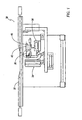
- FIG. 8 is a top view of an adapter assembly according to an embodiment of the present invention.
- FIG. 9 is a front elevation view of the adapter assembly of FIG. 8 ;
- FIG. 10 is a side elevation view of the adapter assembly of FIG. 8 ;
- FIG. 11 is a top view of an indexing guide according to an embodiment of the present invention.
- FIG. 12 is a cross-sectional view of the indexing guide of FIG. 11 taken along lines 12-12;
- FIG. 13 is a front elevation view of the indexing guide and cannula hub, wherein the cannula hub is unlocked from the indexing guide and free to rotate;
- FIG. 14 is a front elevation view of the indexing guide and cannula hub, wherein the cannula hub is locked to the indexing guide and prevented from rotating;
- FIG. 15 is a detailed partial cross-sectional view of the indexing guide and cannula hub, wherein the cannula hub is locked to the indexing guide;
- FIG. 16 is a detailed partial cross-sectional view of the indexing guide and cannula hub, wherein the cannula hub is unlocked from the indexing guide.
- Stereotactic breast biopsy system 30 for use in performing fine-needle aspiration and needle core biopsies of the human breast to determine whether a breast lesion is benign or malignant.
- Stereotactic breast biopsy system 30 includes an ergonomically contoured table 32 that comfortably supports the patient (not shown) in a stable, fixed position that exposes the patient's breast.
- Stereotactic breast biopsy system 30 also includes a diagnostic imaging system 34 for targeting the lesion to be biopsied. The location of the target lesion is used by a guidance system 36 to guide insertion of a biopsy needle 38 into the patient.
- the biopsy needle 38 is a component of a biopsy device 40 that is supported by guidance system 36 in an adapter 42.
- An exemplary biopsy device for use in stereotactic breast biopsy system 30 is the biopsy device marketed by the assignee of the present invention, Suros Surgical Systems, Inc. of Indianapolis, Indiana, under the name ATECTM (Automated Tissue Excision and Collection) and disclosed in U.S. Patent Applications Serial Nos. 09/707,022 and U.S. Patent No. 6,638,235 , which are also owned by the assignee of the present invention.
- biopsy device 40 includes a biopsy needle or cutting element 44 mounted to a handpiece 46.
- the cutting element 44 includes an outer cannula 48 defining a tissue receiving opening 50 and an inner cannula 52 concentrically disposed within the outer cannula 48.
- An outer cannula hub 54 is removably mounted to the handpiece 46 and is connected to the outer cannula 48. As shown in FIG. 4 , outer cannula hub 54 allows removal of handpiece 46 and inner cannula 52 from outer cannula 48, leaving outer cannula 48 positioned within the breast tissue to serve as an introducer for biopsy site markers, therapeutics or the like.
- Adapter 42 includes a base 62 upon which a handpiece cradle 64 is moveably secured.
- Base 62 is attached to guidance system 36 and handpiece cradle 64 receives handpiece 46 of biopsy device 40, as shown in FIG. 7 .
- Handpiece 46 is rotatable within handpiece cradle 64 and can be locked in any one of several angular positions within handpiece cradle 64 by a pivotable clamp 66.
- Clamp 66 is attached to handpiece cradle 64 and is pivotable between an unlocked position, wherein the handpiece 46 is free to rotate within handpiece cradle 64, and a locked position shown in FIGS. 6 and 7 , wherein clamp 66 engages an outer surface of handpiece 46 to inhibit rotation. Additionally, clamp 66 cooperates with handpiece cradle 64 to inhibit axial movement of handpiece 46, i.e., movement along axis Z in FIG. 6 , when clamp 66 is pivoted to the locked position.
- Handpiece cradle 64 is moveable between a pre-deployment position, in which cutting element 44 is removed from the patient's breast tissue, and a post deployment position, in which cutting element 44 is inserted in the patient's breast tissue.
- a deployment mechanism is provided between handpiece cradle 64 and base 62, which is operable to rapidly move handpiece cradle 64 and biopsy device 40 relative to base 62 along the Z-axis.
- the deployment mechanism includes a gear rack 68 attached to handpiece cradle 64 and a lever 70 moveably attached to base 62.
- Lever 70 which includes a geared cam end 72 intermeshed with gear rack 68, is rotatable about a pivot point 74 to move gear rack 68 and handpiece cradle 64 between a deployed position and a cocked position ready for deployment.
- the deployment mechanism also includes a release member 76 that is engagable with handpiece cradle 64 in the cocked position and selectively disengagable therefrom to release handpiece cradle 64 for movement toward the deployed position.
- the deployment mechanism includes at least one spring that provides the force necessary to move handpiece cradle 64 toward the deployed position.
- the spring is energized when handpiece cradle 64 is moved to the cocked position and forces handpiece cradle 64 toward the deployed position when release member 76 is disengaged from handpiece cradle 64.
- the spring is a torsion or coil spring that is disposed between base 62 and lever 70. As lever 70 is rotated about pivot point 74 to move handpiece cradle 64 to the cocked position, the coil spring is energized. When handpiece cradle 64 is released for movement toward the deployed position, the coil spring forces rotation of lever 70 and a corresponding movement of handpiece cradle 64 via gear rack 68.
- the deployment mechanism may also includes a safety 77 that is operably connected to release member 76.
- the safety 77 prevents accidental disengagement of release member 76 from handpiece cradle 64, but is manipuable to selectively permit disengagement of release member 76 from handpiece cradle 64 when so desired.
- the above-described deployment mechanism configuration is provided for example only and is not intended to limit the scope of the present invention.
- Adapter 42 also includes an indexing or "cannula" guide 80 that is secured for movement with handpiece cradle 64.
- indexing guide 80 includes a generally circular-shaped receptacle 82 within which a portion of outer cannula hub 54 is received. Outer cannula hub 54 is rotatable within receptacle 82 or may be locked in any one of several angular positions. Additionally, indexing guide 80 inhibits axial movement (i.e., movement along the Z-axis) of outer cannula hub 54 relative to handpiece cradle 64 and indexing guide 80.
- a portion of outer cannula hub 54 includes at least one notch 84 in an outer circumferential surface 86 thereof.
- indexing guide 80 includes at least one guide lock 88 that is moveably attached to indexing guide 80.
- outer cannula hub 54 is rotatable within receptacle 82 to align notch 84 with guide lock 88.
- Guide lock 88 is moveable generally perpendicular to the Z-axis between an unlocked position (see FIGS. 13 and 16 ), wherein guide lock 88 is disengaged with outer cannula hub 54, and a locked position (see FIGS.
- outer cannula hub 54 can neither rotate nor move axially with respect to indexing guide 80 and handpiece cradle 64.
- outer cannula hub 54 may include a plurality of notches 84, as shown in the drawings.
- indexing guide 80 is generally U-shaped when viewed from above (see FIG. 11 ) having a pair of legs 90, which are attachable to cradle 64, and a base 92 within which receptacle 82 is positioned.
- Base 92 includes a pair of slightly tapered channels 94 within which a guide lock 88 is movably received.
- each guide lock 88 is movably secured within channel 94 by a fastener 96, such as a screw or the like.
- guide locks 88 may include an elongated slot 98 within which fastener 96 is disposed.
- Guide locks 88 may optionally include one or more dimples 100 that extend from a lower surface thereof and are received in a hole 102 in base 92 to resist accidental movement of guide locks 88 between the locked and unlocked positions.
- base 92 may include a lip 104 adjacent receptacle 82 having an inner diameter slightly smaller than the inner diameter of receptacle 82.
- Cannula hub 54 engages lip 104 when received within receptacle 82 to prevent movement of cannula hub 54 in a first direction along the Z-axis.
- Base 92 may also include a pair of grooves 106 that extend from channels 94 into receptacle 82 to permit movement of at least a portion of guide locks 88 into receptacle 82.
- guide locks 88 include an engagement end 108 configured for receipt into notches 84 on cannula hub 54.
- engagement end 108 is received in a notch 84 to inhibit both rotation and axial movement of cannula hub 54 in a second direction along the Z-axis opposite the first direction inhibited by lip 104.
- cannula hub 54 is free to rotate within receptacle 82.
- the adapter 42 of the present invention provides the ability to lock biopsy device 40 into the adapter 42 to inhibit movement therebetween, and maintains registration with the biopsy site throughout a biopsy procedure.
- the adapter 42 facilitates the removal of handpiece 46 and inner cannula 52 from outer cannula 48 by unlocking clamp 66 from handpiece 46 and leaving guide locks 88 engaged with outer cannula hub 54.
- This feature allows the outer cannula 48 to remain in position within the patient's breast tissue to serve as an introducer for biopsy site markers and therapeutics.
- adapter 42 maintains consistent registration of the outer cannula 48 with the biopsy site, even after the handpiece 46 and inner cannula 52 are removed from the outer cannula 48.
- the adapter of the present invention also allows the handpiece 46, inner cannula 52, outer cannula hub 54 and outer cannula 48 to be removed from the adapter 42 during a biopsy procedure and replaced with a separate medical instrument (not shown), such as an applicator device that allows the insertion of a site maker and therapeutics.
- the separate applicator device may include a cannula hub substantially similar to outer cannula hub 54 found in biopsy device 40.
- the outer cannula in the applicator device includes an open end, instead of an end having a trocar tip and a tissue receiving opening 50.
Landscapes
- Health & Medical Sciences (AREA)
- Life Sciences & Earth Sciences (AREA)
- Surgery (AREA)
- Heart & Thoracic Surgery (AREA)
- Pathology (AREA)
- Engineering & Computer Science (AREA)
- Biomedical Technology (AREA)
- Medical Informatics (AREA)
- Molecular Biology (AREA)
- Animal Behavior & Ethology (AREA)
- General Health & Medical Sciences (AREA)
- Public Health (AREA)
- Veterinary Medicine (AREA)
- Oral & Maxillofacial Surgery (AREA)
- Nuclear Medicine, Radiotherapy & Molecular Imaging (AREA)
- Surgical Instruments (AREA)
Abstract
Claims (10)
- Système de biopsie (30) ayant un dispositif (40) de biopsie supporté par un adaptateur (42), le dispositif (40) de biopsie comprenant une pièce à main (46) et un élément (44) coupant ayant une tulipe (54) de la canule extérieure montée de manière amovible sur la pièce à main (46), l'élément (44) coupant comprenant une canule (48) extérieure reliée à la tulipe (54) de la canule extérieure et définissant une ouverture (50) recevant un tissu et une canule (52) intérieure disposée dans la canule (48) extérieure et adjointe à la pièce à main (46), la tulipe (54) de la canule extérieure permettant de retirer la pièce à main (46) et la canule (52) intérieure de la canule (48) extérieure, l'adaptateur (42) comprenant :une base (62) ;un berceau (64) monté mobile sur la base (62) et configuré pour empêcher un mouvement axial du dispositif (40) de biopsie par rapport au berceau (64) lorsqu'il y est verrouillé ;un guide (80) d'indexation mobile avec le berceau (64), caractérisé en ce que le berceau (64) est configuré pour y supporter à rotation le dispositif (40) de biopsie, en ce que le guide (80) d'indexation comprend un réceptacle (82), dans lequel la tulipe (54) de la canule extérieure est reçue à rotation et en ce que le guide (80) d'indexation est configuré pour empêcher une rotation et un mouvement axial de la tulipe (54) de la canule extérieure et de la canule (48) extérieure par rapport au guide (80) d'indexation et au berceau (64), lorsque la tulipe (54) de la canule extérieure y est verrouillée.
- Système suivant la revendication 1, dans lequel le guide (80) d'indexation comprend au moins un verrou (88) de guidage, qui peut coopérer d'une manière sélective avec la tulipe (54) de la canule extérieure pour en empêcher une rotation et un mouvement axial.
- Système suivant la revendication 2, dans lequel le guide (80) d'indexation comprend deux verrous (88) de guidage.
- Système suivant la revendication 2, dans lequel le verrou (88) de guidage est fixé de manière amovible au guide (80) d'indexation.
- Système suivant la revendication 2, dans lequel la tulipe (54) de la canule extérieure comprend au moins une encoche (84) et le verrou (88) de guidage est configuré pour être reçu dans l'encoche (84) afin d'empêcher un mouvement de la tulipe (54) de la canule extérieure dans une première direction axiale.
- Système suivant la revendication 1, dans lequel le guide (80) d'indexation comprend une lèvre (104) voisine du réceptacle (82) pour empêcher un mouvement de la tulipe (54) de la canule extérieure dans une deuxième direction axiale.
- Système suivant la revendication 1, dans lequel le berceau (64) comprend un collier (66) pivotant, qui peut coopérer sélectivement avec la pièce à main (46) pour en empêcher une rotation et un mouvement axial.
- Système suivant la revendication 1, dans lequel l'adaptateur (42) comprend un mécanisme de déploiement configuré pour déplacer le berceau (64) par rapport à la base (62).
- Système (30) suivant la revendication 2, dans lequel la tulipe (54) de la canule extérieure comprend au moins une encoche (84) et le verrou (88) de guidage est configuré pour être reçu dans l'encoche (84) pour empêcher un mouvement de la tulipe (54) de la canule extérieure dans une première direction axiale.
- Système (30) suivant la revendication 1, comprenant, en outre, un mécanisme de déploiement configuré pour déplacer le berceau (64) par rapport à la base (62).
Applications Claiming Priority (5)
| Application Number | Priority Date | Filing Date | Title |
|---|---|---|---|
| US45599203P | 2003-03-19 | 2003-03-19 | |
| US10/803,698 US7628762B2 (en) | 2003-03-19 | 2004-03-18 | Adapter assembly for stereotactic biopsy |
| US803698 | 2004-03-18 | ||
| PCT/US2004/008380 WO2004084738A1 (fr) | 2003-03-19 | 2004-03-19 | Ensemble adaptateur pour biopsie stereotaxique |
| US455992P | 2010-10-29 |
Publications (2)
| Publication Number | Publication Date |
|---|---|
| EP1605830A1 EP1605830A1 (fr) | 2005-12-21 |
| EP1605830B1 true EP1605830B1 (fr) | 2011-05-18 |
Family
ID=33101227
Family Applications (1)
| Application Number | Title | Priority Date | Filing Date |
|---|---|---|---|
| EP04757848A Expired - Lifetime EP1605830B1 (fr) | 2003-03-19 | 2004-03-19 | Ensemble adaptateur pour biopsie stereotaxique |
Country Status (4)
| Country | Link |
|---|---|
| US (2) | US7628762B2 (fr) |
| EP (1) | EP1605830B1 (fr) |
| JP (1) | JP4476282B2 (fr) |
| WO (1) | WO2004084738A1 (fr) |
Families Citing this family (28)
| Publication number | Priority date | Publication date | Assignee | Title |
|---|---|---|---|---|
| US7988642B2 (en) * | 2003-10-14 | 2011-08-02 | Suros Surgical Systems, Inc. | Vacuum assisted biopsy device |
| US8048003B2 (en) * | 2003-10-14 | 2011-11-01 | Suros Surgical Systems, Inc. | Vacuum assisted biopsy device |
| WO2005037106A2 (fr) | 2003-10-14 | 2005-04-28 | Suros Surgical Systems, Inc. | Ensemble d'aiguilles de biopsie par aspiration |
| US8357103B2 (en) | 2003-10-14 | 2013-01-22 | Suros Surgical Systems, Inc. | Vacuum assisted biopsy needle set |
| JP4996467B2 (ja) | 2004-09-27 | 2012-08-08 | アカディア ファーマシューティカルズ インコーポレイテッド | N−(4−フルオロベンジル)−n−(1−メチルピペリジン−4−イル)−n’−(4−(2−メチルプロピルオキシ)フェニルメチル)カルバミド、並びにその酒石酸塩及び結晶形態の合成 |
| US11241296B2 (en) | 2005-11-17 | 2022-02-08 | Breast-Med, Inc. | Imaging fiducial markers and methods |
| US7702378B2 (en) | 2005-11-17 | 2010-04-20 | Breast-Med, Inc. | Tissue marker for multimodality radiographic imaging |
| US8688198B2 (en) * | 2005-11-22 | 2014-04-01 | Suros Surgical Sytems, Inc. | Surgical site marker delivery system |
| US20080149180A1 (en) * | 2006-12-21 | 2008-06-26 | Parris Earl H | Method of associating a water utility service line to a customer service line |
| US20080221479A1 (en) * | 2007-03-07 | 2008-09-11 | Ritchie Paul G | Integrated Imaging and Biopsy System with Integrated Utilities |
| JP2010531672A (ja) * | 2007-04-16 | 2010-09-30 | ニューロアーム サージカル リミテッド | マニピュレーターおよび外科手術用ツール間の連結のための装置 |
| US8808200B2 (en) | 2007-10-01 | 2014-08-19 | Suros Surgical Systems, Inc. | Surgical device and method of using same |
| US8202229B2 (en) | 2007-10-01 | 2012-06-19 | Suros Surgical Systems, Inc. | Surgical device |
| US8075495B2 (en) * | 2008-06-18 | 2011-12-13 | Devicor Medical Products, Inc. | Biopsy devices with universal probe |
| AU2009322332B2 (en) * | 2008-12-03 | 2014-06-26 | Socorro Medical, Inc. | Reusable handpiece for disposable probes |
| USD621934S1 (en) * | 2009-04-03 | 2010-08-17 | Karl Storz Gmbh & Co. Kg | Medical instrument |
| AU2011329836B2 (en) * | 2010-11-18 | 2016-05-12 | Hologic Inc. | Table for performing medical procedures |
| US9968338B2 (en) | 2012-11-21 | 2018-05-15 | C. R. Bard, Inc. | Core needle biopsy device |
| USD735332S1 (en) | 2013-03-06 | 2015-07-28 | C. R. Bard, Inc. | Biopsy device |
| USD737440S1 (en) | 2013-03-07 | 2015-08-25 | C. R. Bard, Inc. | Biopsy device |
| USD735333S1 (en) | 2013-06-26 | 2015-07-28 | C. R. Bard, Inc. | Biopsy device |
| KR101863804B1 (ko) * | 2013-07-19 | 2018-06-04 | 데비코어 메디컬 프로덕츠, 인코포레이티드 | 생검 디바이스 타겟팅 피처들 |
| US9795455B2 (en) | 2014-08-22 | 2017-10-24 | Breast-Med, Inc. | Tissue marker for multimodality radiographic imaging |
| US10271914B2 (en) | 2015-02-11 | 2019-04-30 | University Of Utah Research Foundation | Microsurgical tool adapters, systems and related methods |
| EP3097839B1 (fr) * | 2015-05-29 | 2017-12-27 | Fundacja Rozwoju Kardiochirurgii Im. Prof. Zbigniewa Religi | Dispositif de fixation d'outil médical laparoscopique |
| JP6984944B2 (ja) * | 2015-06-30 | 2021-12-22 | メリット・メディカル・システムズ・インコーポレイテッドMerit Medical Systems, Inc. | 生検装置を位置決めするためのシステム |
| US20180325500A1 (en) | 2017-05-12 | 2018-11-15 | Devicor Medical Products Inc. | Biopsy device with tip protector and mounting apparatus |
| WO2021178489A1 (fr) * | 2020-03-04 | 2021-09-10 | Devicor Medical Products, Inc. | Verrou coulissant pour dispositif de biopsie |
Family Cites Families (17)
| Publication number | Priority date | Publication date | Assignee | Title |
|---|---|---|---|---|
| DE935625C (de) | 1952-10-18 | 1955-11-24 | Guenther Bodendieck | Exzisionsgeraet |
| US5643286A (en) * | 1994-06-24 | 1997-07-01 | Cytotherapeutics, Inc. | Microdrive for use in stereotactic surgery |
| US5902310A (en) | 1996-08-12 | 1999-05-11 | Ethicon Endo-Surgery, Inc. | Apparatus and method for marking tissue |
| IT1292837B1 (it) * | 1997-04-03 | 1999-02-11 | Alberto Bauer | Apparecchio chirurgico per biopsia. |
| US6551253B2 (en) * | 1997-09-12 | 2003-04-22 | Imagyn Medical Technologies | Incisional breast biopsy device |
| US5871448A (en) | 1997-10-14 | 1999-02-16 | Real World Design And Development Co. | Stepper apparatus for use in the imaging/treatment of internal organs using an ultrasound probe |
| US6193673B1 (en) * | 1998-02-20 | 2001-02-27 | United States Surgical Corporation | Biopsy instrument driver apparatus |
| US6875182B2 (en) | 1998-03-03 | 2005-04-05 | Senorx, Inc. | Electrosurgical specimen-collection system |
| US6007497A (en) * | 1998-06-30 | 1999-12-28 | Ethicon Endo-Surgery, Inc. | Surgical biopsy device |
| US6451027B1 (en) * | 1998-12-16 | 2002-09-17 | Intuitive Surgical, Inc. | Devices and methods for moving an image capture device in telesurgical systems |
| US6514215B1 (en) * | 1999-10-13 | 2003-02-04 | Pentax Corporation | Endoscopic tissue collecting instrument |
| US6889073B2 (en) | 2000-05-08 | 2005-05-03 | David A. Lampman | Breast biopsy and therapy system for magnetic resonance imagers |
| US6758824B1 (en) * | 2000-11-06 | 2004-07-06 | Suros Surgical Systems, Inc. | Biopsy apparatus |
| US6659956B2 (en) * | 2001-06-29 | 2003-12-09 | Barzell-Whitmore Maroon Bells, Inc. | Medical instrument positioner |
| US7166114B2 (en) * | 2002-09-18 | 2007-01-23 | Stryker Leibinger Gmbh & Co Kg | Method and system for calibrating a surgical tool and adapter thereof |
| US7438692B2 (en) * | 2002-10-18 | 2008-10-21 | Mark Tsonton | Localization mechanism for an MRI compatible biopsy device |
| US7166144B2 (en) * | 2003-04-16 | 2007-01-23 | Cognis Corporation | Interlaced series parallel configuration for metal solvent extraction plants |
-
2004
- 2004-03-18 US US10/803,698 patent/US7628762B2/en not_active Expired - Lifetime
- 2004-03-19 WO PCT/US2004/008380 patent/WO2004084738A1/fr not_active Ceased
- 2004-03-19 EP EP04757848A patent/EP1605830B1/fr not_active Expired - Lifetime
- 2004-03-19 JP JP2006507345A patent/JP4476282B2/ja not_active Expired - Fee Related
-
2009
- 2009-11-23 US US12/624,194 patent/US8246551B2/en not_active Expired - Lifetime
Also Published As
| Publication number | Publication date |
|---|---|
| WO2004084738A1 (fr) | 2004-10-07 |
| JP2006520653A (ja) | 2006-09-14 |
| US7628762B2 (en) | 2009-12-08 |
| JP4476282B2 (ja) | 2010-06-09 |
| EP1605830A1 (fr) | 2005-12-21 |
| US8246551B2 (en) | 2012-08-21 |
| US20040230133A1 (en) | 2004-11-18 |
| US20100069787A1 (en) | 2010-03-18 |
Similar Documents
| Publication | Publication Date | Title |
|---|---|---|
| US8246551B2 (en) | Adapter assembly for stereotactic biopsy | |
| US20220151727A1 (en) | Marking device with retractable cannula | |
| JP4860182B2 (ja) | Mri生検装置 | |
| US7708751B2 (en) | MRI biopsy device | |
| EP1026992B1 (fr) | Dispositif de biopsie | |
| AU2001285281B2 (en) | Biopsy system | |
| EP3307178B1 (fr) | Mri système de biopsie | |
| EP1051946A2 (fr) | Dispositif pour enlever des tissus | |
| US20100114031A1 (en) | Introducer localization assemblies | |
| CA2580181A1 (fr) | Methode de biopsie | |
| US8688198B2 (en) | Surgical site marker delivery system | |
| WO2002062228A1 (fr) | Appareil et methode de biopsie | |
| WO1996010953A1 (fr) | Gide multi-canule transcutane destine a des biopsies et a d'autres interventions transcutanees | |
| HK1246122A1 (en) | Mri biopsy system |
Legal Events
| Date | Code | Title | Description |
|---|---|---|---|
| PUAI | Public reference made under article 153(3) epc to a published international application that has entered the european phase |
Free format text: ORIGINAL CODE: 0009012 |
|
| 17P | Request for examination filed |
Effective date: 20051013 |
|
| AK | Designated contracting states |
Kind code of ref document: A1 Designated state(s): AT BE BG CH CY CZ DE DK EE ES FI FR GB GR HU IE IT LI LU MC NL PL PT RO SE SI SK TR |
|
| AX | Request for extension of the european patent |
Extension state: AL LT LV MK |
|
| DAX | Request for extension of the european patent (deleted) | ||
| RBV | Designated contracting states (corrected) |
Designated state(s): DE ES FR GB |
|
| RIN1 | Information on inventor provided before grant (corrected) |
Inventor name: HOFMANN, RONALD, L. Inventor name: MILLER, MICHAEL, E. Inventor name: HARDIN, TERRY D Inventor name: MARK, JOSEPH, L. |
|
| 17Q | First examination report despatched |
Effective date: 20090506 |
|
| GRAP | Despatch of communication of intention to grant a patent |
Free format text: ORIGINAL CODE: EPIDOSNIGR1 |
|
| GRAS | Grant fee paid |
Free format text: ORIGINAL CODE: EPIDOSNIGR3 |
|
| GRAA | (expected) grant |
Free format text: ORIGINAL CODE: 0009210 |
|
| AK | Designated contracting states |
Kind code of ref document: B1 Designated state(s): DE ES FR GB |
|
| REG | Reference to a national code |
Ref country code: GB Ref legal event code: FG4D |
|
| REG | Reference to a national code |
Ref country code: DE Ref legal event code: R096 Ref document number: 602004032724 Country of ref document: DE Effective date: 20110630 |
|
| PG25 | Lapsed in a contracting state [announced via postgrant information from national office to epo] |
Ref country code: ES Free format text: LAPSE BECAUSE OF FAILURE TO SUBMIT A TRANSLATION OF THE DESCRIPTION OR TO PAY THE FEE WITHIN THE PRESCRIBED TIME-LIMIT Effective date: 20110829 |
|
| PLBE | No opposition filed within time limit |
Free format text: ORIGINAL CODE: 0009261 |
|
| STAA | Information on the status of an ep patent application or granted ep patent |
Free format text: STATUS: NO OPPOSITION FILED WITHIN TIME LIMIT |
|
| 26N | No opposition filed |
Effective date: 20120221 |
|
| REG | Reference to a national code |
Ref country code: DE Ref legal event code: R097 Ref document number: 602004032724 Country of ref document: DE Effective date: 20120221 |
|
| PGFP | Annual fee paid to national office [announced via postgrant information from national office to epo] |
Ref country code: DE Payment date: 20130327 Year of fee payment: 10 Ref country code: FR Payment date: 20130405 Year of fee payment: 10 Ref country code: GB Payment date: 20130327 Year of fee payment: 10 |
|
| REG | Reference to a national code |
Ref country code: DE Ref legal event code: R119 Ref document number: 602004032724 Country of ref document: DE |
|
| GBPC | Gb: european patent ceased through non-payment of renewal fee |
Effective date: 20140319 |
|
| REG | Reference to a national code |
Ref country code: FR Ref legal event code: ST Effective date: 20141128 |
|
| REG | Reference to a national code |
Ref country code: DE Ref legal event code: R119 Ref document number: 602004032724 Country of ref document: DE Effective date: 20141001 |
|
| PG25 | Lapsed in a contracting state [announced via postgrant information from national office to epo] |
Ref country code: GB Free format text: LAPSE BECAUSE OF NON-PAYMENT OF DUE FEES Effective date: 20140319 Ref country code: FR Free format text: LAPSE BECAUSE OF NON-PAYMENT OF DUE FEES Effective date: 20140331 Ref country code: DE Free format text: LAPSE BECAUSE OF NON-PAYMENT OF DUE FEES Effective date: 20141001 |