EP1606076B1 - Selbstdiagnostizierende vorrichtung zur befestigung von selbststanzenden muttern - Google Patents
Selbstdiagnostizierende vorrichtung zur befestigung von selbststanzenden muttern Download PDFInfo
- Publication number
- EP1606076B1 EP1606076B1 EP03790241A EP03790241A EP1606076B1 EP 1606076 B1 EP1606076 B1 EP 1606076B1 EP 03790241 A EP03790241 A EP 03790241A EP 03790241 A EP03790241 A EP 03790241A EP 1606076 B1 EP1606076 B1 EP 1606076B1
- Authority
- EP
- European Patent Office
- Prior art keywords
- slug
- panel
- plunger
- pierce nut
- pierce
- Prior art date
- Legal status (The legal status is an assumption and is not a legal conclusion. Google has not performed a legal analysis and makes no representation as to the accuracy of the status listed.)
- Expired - Lifetime
Links
- 238000009434 installation Methods 0.000 title claims abstract description 127
- 239000000523 sample Substances 0.000 claims description 68
- 230000004323 axial length Effects 0.000 claims description 10
- 241000237858 Gastropoda Species 0.000 description 27
- 239000002184 metal Substances 0.000 description 7
- 238000012423 maintenance Methods 0.000 description 6
- 230000008439 repair process Effects 0.000 description 4
- 238000013461 design Methods 0.000 description 3
- 239000000835 fiber Substances 0.000 description 3
- 238000004519 manufacturing process Methods 0.000 description 3
- 238000012544 monitoring process Methods 0.000 description 3
- 230000000712 assembly Effects 0.000 description 2
- 238000000429 assembly Methods 0.000 description 2
- 238000007689 inspection Methods 0.000 description 2
- 238000000034 method Methods 0.000 description 2
- 238000011179 visual inspection Methods 0.000 description 2
- 230000004888 barrier function Effects 0.000 description 1
- 230000000903 blocking effect Effects 0.000 description 1
- 238000012937 correction Methods 0.000 description 1
- 230000007246 mechanism Effects 0.000 description 1
- 238000012986 modification Methods 0.000 description 1
- 230000004048 modification Effects 0.000 description 1
- 230000008569 process Effects 0.000 description 1
- 230000000717 retained effect Effects 0.000 description 1
- 238000007789 sealing Methods 0.000 description 1
Images

Classifications
-
- B—PERFORMING OPERATIONS; TRANSPORTING
- B23—MACHINE TOOLS; METAL-WORKING NOT OTHERWISE PROVIDED FOR
- B23P—METAL-WORKING NOT OTHERWISE PROVIDED FOR; COMBINED OPERATIONS; UNIVERSAL MACHINE TOOLS
- B23P19/00—Machines for simply fitting together or separating metal parts or objects, or metal and non-metal parts, whether or not involving some deformation; Tools or devices therefor so far as not provided for in other classes
- B23P19/04—Machines for simply fitting together or separating metal parts or objects, or metal and non-metal parts, whether or not involving some deformation; Tools or devices therefor so far as not provided for in other classes for assembling or disassembling parts
- B23P19/06—Screw or nut setting or loosening machines
- B23P19/062—Pierce nut setting machines
-
- Y—GENERAL TAGGING OF NEW TECHNOLOGICAL DEVELOPMENTS; GENERAL TAGGING OF CROSS-SECTIONAL TECHNOLOGIES SPANNING OVER SEVERAL SECTIONS OF THE IPC; TECHNICAL SUBJECTS COVERED BY FORMER USPC CROSS-REFERENCE ART COLLECTIONS [XRACs] AND DIGESTS
- Y10—TECHNICAL SUBJECTS COVERED BY FORMER USPC
- Y10T—TECHNICAL SUBJECTS COVERED BY FORMER US CLASSIFICATION
- Y10T29/00—Metal working
- Y10T29/49—Method of mechanical manufacture
- Y10T29/49826—Assembling or joining
- Y10T29/49833—Punching, piercing or reaming part by surface of second part
- Y10T29/49835—Punching, piercing or reaming part by surface of second part with shaping
- Y10T29/49837—Punching, piercing or reaming part by surface of second part with shaping of first part
-
- Y—GENERAL TAGGING OF NEW TECHNOLOGICAL DEVELOPMENTS; GENERAL TAGGING OF CROSS-SECTIONAL TECHNOLOGIES SPANNING OVER SEVERAL SECTIONS OF THE IPC; TECHNICAL SUBJECTS COVERED BY FORMER USPC CROSS-REFERENCE ART COLLECTIONS [XRACs] AND DIGESTS
- Y10—TECHNICAL SUBJECTS COVERED BY FORMER USPC
- Y10T—TECHNICAL SUBJECTS COVERED BY FORMER US CLASSIFICATION
- Y10T29/00—Metal working
- Y10T29/53—Means to assemble or disassemble
- Y10T29/5343—Means to drive self-piercing work part
-
- Y—GENERAL TAGGING OF NEW TECHNOLOGICAL DEVELOPMENTS; GENERAL TAGGING OF CROSS-SECTIONAL TECHNOLOGIES SPANNING OVER SEVERAL SECTIONS OF THE IPC; TECHNICAL SUBJECTS COVERED BY FORMER USPC CROSS-REFERENCE ART COLLECTIONS [XRACs] AND DIGESTS
- Y10—TECHNICAL SUBJECTS COVERED BY FORMER USPC
- Y10T—TECHNICAL SUBJECTS COVERED BY FORMER US CLASSIFICATION
- Y10T29/00—Metal working
- Y10T29/53—Means to assemble or disassemble
- Y10T29/53478—Means to assemble or disassemble with magazine supply
- Y10T29/53522—Means to fasten by deforming
-
- Y—GENERAL TAGGING OF NEW TECHNOLOGICAL DEVELOPMENTS; GENERAL TAGGING OF CROSS-SECTIONAL TECHNOLOGIES SPANNING OVER SEVERAL SECTIONS OF THE IPC; TECHNICAL SUBJECTS COVERED BY FORMER USPC CROSS-REFERENCE ART COLLECTIONS [XRACs] AND DIGESTS
- Y10—TECHNICAL SUBJECTS COVERED BY FORMER USPC
- Y10T—TECHNICAL SUBJECTS COVERED BY FORMER US CLASSIFICATION
- Y10T29/00—Metal working
- Y10T29/53—Means to assemble or disassemble
- Y10T29/53709—Overedge assembling means
Definitions
- This invention relates to a pierce nut installation apparatus which continuously monitors the pierce nut installation and automatically shuts down the die press in the event that the last pierce nut is not properly installed.
- pierce nuts are typically installed in a metal plate or panel by an installation apparatus including an installation head generally attached to the upper die platen or shoe of a reciprocating die press and a die member or die button installed in the lower die shoe or die platen, wherein the panel is fixed to the lower die shoe or die platen overlying the die button.
- Pierce nuts are fed to the installation head opposite a reciprocating plunger which, upon closing of the die press, drives the pierce nut into the panel, piercing a slug from the panel, and the die button then installs the pierce nut in the pierced panel opening.
- the slug pierced from the panel is then received in an opening in the die button, which typically retains several slugs before ejecting the slugs.
- the panel may be simultaneously formed by the die press and several pierce nuts may be simultaneously installed in the panel with each stroke of the die press, particularly in mass production applications.
- the panel slug may remain attached or partially attached to the panel causing potential quality issues during the assembly operation, wherein the panel having the pierce nut attached is assembled to a second component. In the automotive industry, for example, the assembly operation is typically carried out at a different location.
- Another problem associated with the installation of pierce nuts is the stacking of the panel slugs in the die button opening.
- the pierce nut installation apparatus of this invention is self-monitoring. That is, the pierce nut installation apparatus of this invention continuously monitors the installation of each pierce nut by the pierce nut installation head and the slugs pierced from the panel to assure continued proper installation of pierce nuts or shut down the die press for maintenance or repair prior to installation of the next pierce nut.
- the sensors in the pierce nut installation apparatus of this invention are connected to the computer logic of the die press.
- the press is stopped at the top of the stroke for maintenance of the pierce nut installation apparatus or die press, permitting immediate correction of the problem and avoiding incorrectly installed pierce nuts and potential scrap of further panel assemblies.
- the pierce nut installation head of this invention includes a plunger passage and a pierce nut feed passage intersecting the plunger passage.
- a feed mechanism feeds pierce nuts through the feed passage into the plunger passage opposite a reciprocating plunger in the plunger passage.
- the plunger Upon closing of the die press, the plunger reciprocates through the plunger passage to install a pierce nut in a panel supported on a die button as described above.
- a conventional pierce nut includes a projecting pilot portion, flange portions on at least opposed sides of the pilot portion and a bore extending through the pilot portion.
- the pilot portion pierces a slug from the panel in cooperation with the die button and the die button then deforms the panel metal adjacent the pierced panel opening into a groove or grooves in the pierce nut, permanently attaching the pierce nut to the panel.
- the pierced panel slug is then received in a central opening in the die button.
- a slug probe rod is telescopically received through the plunger having a proximal end initially generally parallel to or spaced above the free proximal end of the plunger, opposite the pierce nut in the plunger passage when the die press is in the open position, and a distal end which is resiliently biased toward the proximal end of the plunger.
- the slug probe rod preferably has an axial length greater than the axial length of the plunger such that, upon closing of the die press, the slug probe rod extends through the plunger into the pierce nut bore a distance greater than the thickness of the pilot portion of the pierce nut if a slug has been pierced from the panel. If a slug has not been pierced from the panel, the proximal end of the slug probe rod will engage the panel indicating that a pierce nut has not been properly installed in the panel or a slug has not been fully pierced from the panel.
- the distal end of the plunger of a conventional pierce nut installation head may be fixed to or spaced from the back-up plate attached to the upper die platen.
- the distal end of the plunger engages the back-up plate or is fixed to the back-up plate and the proximal end of the plunger drives the pierce nut through the plunger passage.
- the slug probe rod is resiliently biased toward the proximal end of the plunger, the proximal end of the slug probe rod is then received into the bore of the pierce nut to either engage the panel, if a slug has not been fully pierced from the panel, or through the nut bore if a slug has been pierced from the panel.
- the slug probe rod also serves the function of removing a slug from the panel in the event that a slug is partially pierced from the panel and hanging, for example, from the panel.
- a sensor of the pierce nut installation head determines whether the slug probe rod has been received through the pierce nut bore and signals the computer logic of the die press to recycle the die press and install a second pierce nut in a second panel. However, if the sensor determines that the slug rod probe has not been received through the pierce nut bore, the sensor signals the computer logic of the die press to stop the press, preferably at the top of the stroke of the die press, when the press is open, for inspection, repair and maintenance as required.
- the slug probe rod is mechanically biased toward the proximal end of the plunger by a conventional coil spring.
- the distal end of the slug probe rod includes an enlarged head portion and the spring is biased against the enlarged head portion of the slug probe rod.
- the slug probe rod is resiliently biased toward the proximal end of the plunger by pneumatic pressure.
- the back-up plate includes a bore which receives an enlarged distal end of the slug probe rod which has an O-ring or other sealing means and pneumatic pressure resiliently biases the slug probe rod toward the proximal end of the plunger.
- proximal refers to a component or a portion of a component closest to the pierce nut in the plunger passage and the term “distal” refers to a component or a portion of a component furthest from the pierce nut in the plunger passage.
- distal refers to a component or a portion of a component furthest from the pierce nut in the plunger passage.
- the pierce nut installation head of this invention includes a probe or sensor which senses the location and movement of the distal end of the slug probe rod.
- the die button fully ejects the panel slug from the bore in the die button following installation of a pierce nut in a panel contrary to the teaching of the prior art.
- a conventional die button typically retains several panel slugs before injecting the slugs from the die button to prevent a panel slug from adhering to the panel following installation.
- the opening through the die button is generally rectangular to receive rectangular panel slugs, but the die button bore includes rounded corners which receive and retain a plurality of panel slugs and prevent the panel slugs from being drawn upwardly against the panel upon opening of the die press and removal of the panel from the die press.
- a vacuum may be created following installation and the panel slugs then fall from the panel during handling, littering the workplace.
- the resiliently biased slug probe rod of the installation head of this invention positively ejects the slug through the die button bore, preventing the slug from being drawn against the panel.
- the opening through the die button is generally frustoconical, having an opening configured to receive the panel slug and tapered radially outwardly to assure complete ejection of the panel slug through the die button bore.
- the self-monitoring pierce nut installation apparatus of this invention may also be used to determine whether a panel slug is received through the die button, indicating that the panel has not only been pierced, but also that the pierced panel slug has been fully removed from the panel and discharged through the die button.
- the current design of the pierce nut die button, the die button retains several slugs which, on occasion, can cold weld together, blocking the opening through the die button and resulting in improper installation of the pierce nuts or requiring greater force to remove the slugs.
- Another problem is that the slug may only be partially pierced from the panel and hangs from the panel as described above.
- the pierce nut installation apparatus of this invention preferably includes a slug sensor which determines whether the pierced panel slug is received through the central opening or bore in the die button and discharged.
- the slug sensor is also connected to the computer logic of the die press. If a slug is received through the opening through the die button and discharged, the sensor signals the computer logic of the die press to recycle the press and install a pierce nut in a second panel as described above. If, however, the slug sensor indicates that a slug has not been received through the central opening of the die button and discharged, the sensor signals the computer logic of the die press to stop the press in the open position for corrective maintenance.
- the pierce nut installation head includes a sensor ring having an opening coaxially aligned with the opening through the die button and a conductive coil surrounds the opening of the ring sensor which creates a magnetic field which signals that a slug has been received through the opening through the die button and discharged.
- the conductive coil can also be located at the exit of the central opening of the die button.
- the sensor includes an infrared beam or similar sensing device which senses the ejection of the pierced panel slug from the die button.
- the slug probe rod sensor and the slug sensor associated with the die button of the pierce nut installation apparatus of this invention may be utilized individually or in combination, but one preferred embodiment of the pierce nut installation head of this invention includes both features.
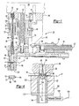
- Figure 1 is a side cross-sectional view of one embodiment of a pierce nut installation head of this invention
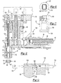
- Figure 2 is a side cross-sectional view of an alternative embodiment of a pierce nut installation head of this invention
- Figure 3 is a partial end cross-sectional view of Figure 2 in the direction of view arrows 3-3;
- Figure 4 is a partial side cross-sectional view of Figures 1 and 2 illustrating one embodiment of a slug sensor
- Figures 5A to 5C are partial side cross-section views of the pierce nut installation head shown in Figures 1 and 2 illustrating the sequence of installation of a pierce nut in a panel and an alternative embodiment of a slug sensor;
- Figure 6 is a top view of one preferred embodiment of the die button illustrated in the Figures 4 and 5A to 5C ;
- Figure 7 is a side partially cross-sectioned view of Figure 6 .
- Figure 1 illustrates one embodiment of the pierce nut installation apparatus of this invention which includes a pierce nut installation head 20 and a die button 22.
- a conventional pierce nut installation apparatus includes a pierce nut installation head typically attached to the upper die shoe or die platen of a die press (not shown) and a die member or die button is typically attached to the lower die shoe or die platen of the die press. Pierce nuts are received by the installation head and a pierce nut is installed with each stroke of the die press.
- the disclosed embodiment of the pierce nut installation head 20 includes a pierce nut feed passage 24 and a transverse plunger passage 26 which intersects and communicates with the feed passage 24 and a plunger 28 reciprocates through the plunger passage 26 to install a pierce nut 64 in a panel P as will be understood by those skilled in this art and further described below.
- a pierce nut 64 described below is shown opposite the plunger passage 26 for reference purposes.
- the plunger 28 includes a distal end 30 which, in this embodiment, reciprocates in an opening 31 in the plunger support cam base 32.
- the cam base 32 includes an inclined surface 36 which receives a roller or rollers (not shown) on the pierce nut feed adapter assembly 38.
- the pierce nut feed adapter assembly 38 includes a coil spring 40 having a rod 42 receiving a feed pawl 44, which is pivotally supported at 46 and the feed pawl 44 includes a finger 50 and a return spring 48 rotates the feed pawl 44 in a counterclockwise direction in Figure 1 .
- the disclosed embodiment of the pierce nut installation head 20 further includes a shank spring 52 which is resiliently biased against a chute attaching pin 54.
- the pierce installation head 20 is mounted on a back-up plate 56 and the back-up plate 56 is mounted on the upper die shoe or die platen 58 of a die press (not shown).
- the disclosed embodiment of the pierce nut installation head 20 further includes a nose assembly 60 which may include a proximity probe 62 presently used to indicate the presence or absence of a pierce nut 64 in the plunger passage 26 of the nose member 60.
- the pierce nut 64 is shown in Figure 1 for reference purposes only and has been rotated for this purpose.
- One embodiment of a pierce nut 64 which may be installed by the pierce nut installation apparatus of this invention includes a central projecting pilot portion 66 having a bore 68 therethrough, flange portions 70 on opposed sides of the pilot portion 66 and dovetail-shaped grooves 72 in the flange portion 70.
- the pierce nut installation head 20 is conventional generally as disclosed in U.S. Patent No. 3,108,368 assigned to the assignee of the predecessor in interest of this application.
- the disclose feed adapter assembly 38 is specifically adapted for feeding pierce nuts interconnected by frangible wires as disclosed, for example, in U.S. Patent No. 3,845,860 , also assigned to the predecessor in interest of the assignee of this application.
- the pierce nut installation head may also be adapted for feeding pierce nuts from a hopper in bulk form as disclosed, for example, in U.S. Patent No. 3,487,976 , also assigned to the predecessor in interest of the assignee of this application.
- pierce nuts 64 are received in the feed passage 24 and fed seriatim from the feed passage 24 to the plunger passage 26 by the feed pawl 44.
- the pierce nut installation head may be attached to the back-up plate 56 by any suitable means, including bolts 74 and the back-up plate 56 is attached to the upper die shoe or die platen 58 by bolts (not shown) and aligned by dowel pins 76.
- the assembly further includes a shank 78 which receives the shank spring 52 and a shank stop pin 80 limits movement of the plunger support cam base 32 and shank 78 relative to the nose assembly 60 as now described. Upon closing of the die press,(not shown) the nose assembly 60 first engages the panel P as shown in Figure 1 .
- the panel P is supported on the die button 22 and the die button 22 is supported in a support block 82 in the lower die shoe or die platen (not shown) of the die press.
- the nose assembly 60 remains stationary relative to the panel P and the plunger 28 is then received against the back-up plate 56 and finally the plunger 28 is driven through the plunger passage 26, wherein the proximal end 84 of the plunger 28 engages a pierce nut 64 to install the pierce nut in the panel P.
- the plunger 28 may be fixed relative to the back-up plate 56.
- the projecting central pilot portion 66 of the pierce nut 64 initially pierces a slug from the panel P and the die button 22 deforms the panel surrounding the pierce panel opening into the grooves 72 as known to those skilled in this art.
- a pierce nut is not always properly installed in the panel, particularly in mass production applications.
- the die press may include several pierce nut installation heads and the panel P may be simultaneously formed by the die press.
- An improper pierce nut installation may result, for example, from improper die press setting, misalignment or improper feeding of the pierce nuts from the feed passage 24 to the plunger passage 26 and other causes.
- Another problem associated with the present design of the pierce nut installation apparatus disclosed in the above-referenced U.S. patents is that the panel slugs may jam and cold weld in the die button bore eventually resulting in improper pierce nut installations.
- improper pierce nut installations may not be discovered in time to prevent continued improper pierce nut installations, particularly where the pierce nut and panel assemblies are transferred to another area for example for assembly.
- Visual inspection by the press operator may not be sufficient to detect improperly installed pierce nuts, particularly where several pierce nuts are installed in each panel by the die press.
- the pierce nut installation apparatus of this invention continuously monitors the pierce nut installation and removal of the panel slugs from the die button without littering the workplace with panel slugs resulting from adherence of the panel slugs to the pierce nut and panel assembly.
- the embodiment of the pierce nut installation head 20 shown in Figure 1 includes a generally cylindrical slug probe rod 86 telescopically received in an axial bore 88 of the plunger 28 preferably, but not necessarily having an axial length greater than the plunger 28.
- the slug probe rod 86 includes an enlarged head portion 90 which is received in a cylindrical bore 92 in the back-up plate 56 and a coil spring 94 resiliently urges the slug probe rod 86 toward the panel P.
- the proximal end 96 of the slug probe rod 86 Prior to installation of a pierce nut in the panel P, is generally parallel to or spaced above the proximal end 84 of the plunger 28 as shown in Figure 1 .
- a sensor connected to the control of the die press monitors the axial position of the slug probe rod 86 to determine whether a slug has been pierced from the panel by the pierce nut 64 and the coil spring 94 ejects the panel slug from the panel through the die button 22, preventing adherence of the panel slug to the pierce nut and panel assembly.
- FIG. 2 illustrates an alternative embodiment of a pierce nut installation head 120 which differs from the pierce nut installation head 20 described above only with regard to the slug probe rod 98 as now described. All of the other components of the pierce nut installation head 120 which may be identical to the pierce nut head 20 described above are numbered the same as the pierce nut installation head 20 and thus no further description of these components is therefore required for a full understanding of the pierce nut installation head 120.
- the slug probe rod 98 includes an enlarged cylindrical head portion 100 which is telescopically received in a cylindrical bore 102 in the plunger 104 and a return spring 101 is biased against the enlarged head portion 100, normally biasing the slug probe rod 98 axially toward the upper die shoe or die platen 58.
- the enlarged head portion 100 includes cylindrical radial flange portions 106 and O ring 108 shown in Figure 3 is sealed against the cylindrical bore 110 in the back-up plate 56.
- the proximal end 112 of the slug probe rod 98 is generally parallel to or spaced above the proximal end 114 of the plunger 104.
- the back-up plate 56 includes a port 116 which receives air under pressure from a source 118 which biases the slug probe rod 98 ( Figure 2 ) axially toward the panel P, serving the same function as the coil spring 94 in Figure 1 .
- the pierce nut installation head (20 or 120) further includes a proximity sensor 122 which senses the axial position of the slug probe rod 98 ( Figure 3 ) which is secured to one side of the back-up plate 56 by any suitable means, such as jam nuts 124, and the proximity sensor 122 includes an electrical wire 126 connected to the computer logic of the die press (not shown) as described below.
- Figures 6 and 7 illustrate in more detail one embodiment of the die button 22 shown in Figures 1 and 2 .
- the disclosed embodiment of the die button 22 includes an annular planar end face 128 surrounding clinching lips 130 which deform the panel metal surrounding the pierce panel opening into the grooves 72 during final installation of the pierce nut in a panel P as is well known to those skilled in this art and described further in the above-referenced U.S. patents.
- the opening 132 through the die lips 130 is generally frustoconical which, in this embodiment, is rectangular and increasing in width from the clinching lips 130 to the enlarged cylindrical opening 134 through the distal end 136 of the die button 22.
- a conventional die button includes a rectangular opening having rounded corners which retain a plurality of panel slugs to prevent the panel slugs from being drawn upwardly against the pierce nut and panel assembly following opening of the die press (not shown). Without this feature, the panel slugs would litter the work area.
- the resiliently biased slug probe rod 86 in Figure 1 and 98 in Figure 2 positively ejects the panel slugs through the generally frustoconical opening 132 and out the enlarged cylindrical opening 134 as described further below.
- one preferred embodiment of the pierce nut installation apparatus of this invention further includes a panel slug sensor associated with the die button which provides further evidence of a proper pierce nut installation.
- the slug sensor may be any conventional sensor including, for example, a fiber optic or infrared sensor, a pneumatic probe, an electromagnetic sensor described below, a magnetic proximity probe, etc.
- Figure 4 illustrates one embodiment of a slug sensor utilizing an infrared sensor, but may alternatively be a fiber optic sensor.
- the infrared sensor 138 is mounted on a tube 140 having an internal diameter generally equal to the internal diameter of the enlarged opening 134 of the die button and the tube 140 is mounted to the back-up plate 142 of the lower die shoe or platen.
- the infrared sensor 138 is then connected by an electrical wire 144 to the computer logic control of the die press (not shown).
- Figures 5A to 5C illustrate an alternative embodiment of a slug sensor and the sequence of operation of the pierce nut installation apparatus of this invention.
- the embodiment of the slug sensor 146 shown in Figures 5A to 5C is an electromagnetic sensor which is particularly suitable for application of pierce nuts in a metal panel, which is a primary application of this invention.
- the electromagnetic slug sensor 146 includes riser plates 148 and 150 on opposed sides of a proximity ring sensor 152.
- the riser plates 148 and 150, particularly the lower riser plate 150 are optional.
- the ring sensor 152 includes a conductive metal coil 154 surrounding a cylindrical opening 156.
- the upper riser plate 148 includes a frustoconical opening 158 coaxially aligned with the opening 134 through of the die button 22.
- the lower riser plate 150 has a cylindrical opening 164 having a diameter slightly greater than the internal diameter of the opening 156 through the ring sensor 152.
- the assembly is bolted by bolts 166 or other suitable fastening means to the support block 82 of the lower die platen, such that the openings 158, 156 and 164 are coaxially aligned with the opening 134 of the die button 22.
- a metal part such as a metal panel slug received through the conductive coil 154 of the ring sensor 150 will generate a magnetic field and an electric current and the ring sensor 152 includes an electrical connector 168 having a wire 170 connected to the computer logic of the die press (not shown) to shut off the press in the event that a slug P is not received through opening 156 of the ring sensor 152 prior to installation of a second pierce nut as now described with regard to Figures 5A to 5C .
- Figure 5A illustrates the position and orientation of the pierce nut installation apparatus of this invention as the nose assembly 60 contacts the panel P as shown in Figures 1 and 2 .
- the pierce nut installation head (20 or 120) is typically installed in the upper die shoe or platen of a die press and the die button 22 is typically installed in the lower die shoe or die platen of a die press (not shown).
- the nose assembly 60 is spaced from the panel P and the die button 22 for receipt of a panel P.
- a pierce nut 64 is received in the plunger passage 26 from the feed passage 24 ( Figures 1 and 2 ) as the press is opened by the feed adapter assembly 38.
- the nose assembly first engages the panel P and the proximal end 84 of the plunger 28 engages a pierce nut 64 received in the plunger passage 26 from the feed passage 24 (see Figures 1 and 2 ).
- the pierce nut 64 is initially retained in the plunger passage 26 by fingers 172 pivotally attached to the nose member 60 by pivot pins 174.
- the plunger 28 includes opposed cam surfaces 176 and the fingers 172 include hook-shaped distal end portions 178 and hook-shaped proximal end portions 180 which rotate the fingers 172 to receive the hook-shaped proximal end portions 180 to retain a pierce nut 64 in the plunger passage 26 as shown in Figure 5A .
- the proximal end 96 of the slug probe rod 86 is then spaced above the proximal end 84 of the plunger 28 as described above with regard to Figure 1 . This would be equally true of the slug probe rod 98 shown in Figure 2 , but for ease of description, the reference numbers for the plunger 28 and the slug probe rod 86 will be taken from Figure 1 .
- Figure 5B illustrates the position of the assembly at the moment the pilot portion 66 of the pierce nut 64 engages the panel P.
- the distal end 30 of the plunger engages the back-up plate 56 as the nose assembly 60 engages the panel and the plunger 28 is then driven through the plunger passage 26 to engage a pierce nut 64.
- the distal end 30 of the plunger 28 is normally spaced from the back-up plate 56 by pneumatic pressure received through port 182.
- the fingers 172 rotate about pivot pins 174 to release the pierce nut 64 as shown in Figure 5B .
- the proximal end 84 of the plunger 28 drives the pilot portion 66 of the pierce nut 64 against the panel P, piercing a slug S from the panel and the clinching lips 130 of the die button (see Figure 7 ) simultaneously deform the panel P surrounding the pierced panel opening into the grooves 72 on opposed sides of the pilot portion 66 (see Figure 1 ), securely retaining the pierce nut 64 to the panel P as disclosed in more detail in U.S. Patent No. 6,226,854 assigned to the assignee of this application.
- the die press (not shown) is now fully closed.
- the proximal end 96 of the slug probe rod 86 will be received through the nut bore 68 (see also Figures 1 and 2 ) under the force of the coil spring 94 in Figure 1 or air pressure through port 116 in Figure 3 as shown in Figure 5C indicating a good pierce nut installation. Further, the pierced panel slug S will be ejected through the opening 134 in the die button 22 by the slug probe rod 86, preventing the panel slug from adhering to the pierce nut and panel assembly and littering the work area.
- a preferred design of the die button 22 includes an opening 132 shown in Figure 7 which is no longer required to retain the panel slugs S, but preferably includes a frustoconical opening 132 which promotes immediate ejection of the panel slugs S.
- the proximal end 96 of the slug probe rod 86 will not be received through the pierce nut bore 68, but will engage the panel P indicating either that the pierce nut 64 has not been installed in the panel P or partially installed in the panel without fully piercing the panel indicating an improper installation.
- the panel slug S is received through the ring sensor 152 creating a magnetic field, as described above, indicating that the panel slug S has been fully ejected from the die button 22.
- the infrared sensor 138 will indicate that the panel slug has been ejected from the tube 140.
- the pierce nut installation apparatus of this invention is thus self-diagnosing, eliminating the requirement for visual inspection of the pierce nut and panel assembly by the die press operator.
- the proximity sensor 122 shown in Figure 3 senses the axial position of the slug probe rod which is connected by wire 126 to the computer logic of the die press (not shown), stopping the die press, preferably in the open position, in the event that the proximal end 96 of the slug probe rod 86 engages the panel P rather than being received through the pierce nut bore 68 indicating either that a pierce nut has not been installed in the panel or an improper pierce nut installation as described above.
- the pierce nut installation apparatus of this invention further includes a slug sensor, such as the infrared sensor 138 shown in Figure 4 or the magnetic ring sensor 152 shown in Figures 5A to 5C
- the ring sensor is connected by wire 170 to the computer logic of the die press to stop the die press in the fully open position.
- stopping the die press in the open position indicates to the die press operator that maintenance or repair is required for proper installation of pierce nuts and reduces scrap particularly in mass production applications.
- several pierce nuts may be installed in a panel with each stroke of the die press and the panel may be simultaneously formed by the die press.
- the sensors of each of the pierce nut installation heads and die buttons may be connected to a control panel which indicates which pierce nut head and die button require inspection and maintenance or repair.
- the self-diagnosing features of this invention may be utilized with any pierce nut or pierce nut installation apparatus, including cold or die formed pierce nuts as disclosed in U.S. Patent No. 3,878,599 assigned to the predecessor in interest of this application and the pierce nut installation head disclosed in U.S. Patent No. 6,631,827 assigned to the assignee of this application.
- the sensors utilized in the pierce nut installation apparatus of this invention including the proximity sensor 122 may be electric, pneumatic, infrared and fiber optic sensors. A suitable proximity sensor is made by Turck Inc. of Plymouth, Minnesota.
- the slug sensors 140 and 152 may be used separately or preferably in combination.
Landscapes
- Engineering & Computer Science (AREA)
- Mechanical Engineering (AREA)
- Automatic Assembly (AREA)
- Perforating, Stamping-Out Or Severing By Means Other Than Cutting (AREA)
- Measuring Pulse, Heart Rate, Blood Pressure Or Blood Flow (AREA)
- Vehicle Body Suspensions (AREA)
- Magnetic Resonance Imaging Apparatus (AREA)
- Investigating Or Analyzing Materials By The Use Of Ultrasonic Waves (AREA)
- Paper (AREA)
Claims (23)
- Eine Stanzbuchseninstallationsvorrichtung zum Installieren von Stanzbuchsen (64) in ein Paneel, jede der Stanzbuchsen (64) hat ein hindurchgehendes Loch (68), umfassend: ein Stanzbuchseninstallationskopf (20) mit einer Stempeldurchführung (26) zum Aufnehmen einer Stanzbuchse (64) zum Installieren in das Paneel; ein Stempel (28), der sich in der Stempeldurchführung (26) hin- und herbewegt, mit einem nahen Ende, der eine Stanzbuchse (64) durch die Stempeldurchführung (26) gegen ein Paneel gegenüber der Stempeldurchführung (26) treibt, der ein Stück aus dem Paneel stanzt und die Stanzbuchse (64) in einer gestanzten Öffnung installiert, die in dem Paneel gebildet wird, die Stempeldurchführung (26) mit einer axialen Öffnung, die teleskopartig einen Stückprobenstab (86) aufnimmt, der nachgiebig in Richtung des nahen Endes des Stempels (28) vorgespannt ist und sich über das nahe Ende des Stempels (28) hinaus durch das Buchsenloch (68) erstreckt, wenn ein Stück aus dem Paneel heraus gestanzt ist, und das Paneel kontaktiert, wenn ein Stück nicht aus dem Paneel herausgestanzt ist; und
ein Sensor (122), der eine axiale Bewegung des Stückprobenstabs (86) erfasst, um zu bestimmen, ob ein Stück aus dem Paneel heraus gestanzt worden ist. - Die Stanzbuchseninstallationsvorrichtung wie in Anspruch 1 definiert, wobei sich die axiale Öffnung in dem Stempel (28) durch den Stempel (28) erstreckt und der Stückprobenstab (86) eine axiale Länge aufweist, die größer ist als eine axiale Länge des Stempels (28).
- Die Stanzbuchseninstallationsvorrichtung wie in Anspruch 1 definiert, wobei die Stanzbuchseninstallationsvorrichtung einen Matrizenknopf (22) beinhaltet, der das Paneel gegenüber der Stempeldurchführung (26) stützt, der eine Öffnung zum Aufnehmen des Stücks aufweist und das nahe Ende des Stückprobenstabs (86) wirft das Stück durch die Öffnung in dem Matrizenknopf (22) aus.
- Die Stanzbuchseninstallationsvorrichtung wie in Anspruch 3 definiert, wobei der Matrizenknopf (22) einen Stücksensor (146) beinhaltet, der die Aufnahme von einem Paneelstück gestanzt aus dem Paneel durch die Öffnung in dem Matrizenknopf (22) feststellt.
- Die Stanzbuchseninstallationsvorrichtung wie in Anspruch 4 definiert, wobei der Stücksensor (146) eine leitende Wicklung beinhaltet, die eine Öffnung in dem Sensor (146) umgibt, die das Paneelstück aufnimmt, und das Paneelstück erzeugt ein magnetisches Feld.
- Die Stanzbuchseninstallationsvorrichtung wie in Anspruch 1 definiert, wobei der Sensor (146) ein Näherungssensor ist.
- Die Stanzbuchseninstallationsvorrichtung wie in Anspruch 1 definiert, wobei der Stückprobenstab (86) in der axialen Öffnung in dem Stempel (28) durch eine Wicklungsfeder (94) nachgiebig vorgespannt ist.
- Die Stanzbuchseninstallationsvorrichtung wie in Anspruch 1 definiert, wobei der Stückprobenstab (86) in der axialen Öffnung in Richtung des nahen Endes des Stempels (28) durch pneumatischen Druck nachgiebig vorgespannt ist.
- Die Stanzbuchseninstallationsvorrichtung wie in Anspruch 1 definiert, wobei der Stückprobenstab (86) eine axiale Länge aufweist, die größer ist als eine axiale Länge des Stempels (28) und der Stückprobenstab (86) ein nahes Ende benachbart zu dem nahen Ende des Stempels (28) vor einer Hin- und Herbewegung von dem Stempel (28) hat.
- Die Stanzbuchseninstallationsvorrichtung wie in Anspruch 1 definiert, wobei der Stückprobenstab (86) in Richtung des nahen Endes des Stempels (28) durch eine Feder vorgespannt ist.
- Die Stanzbuchseninstallationsvorrichtung wie in Anspruch 1 definiert, wobei der Stückprobenstab (86) in Richtung des nahen Endes des Stempels (28) durch pneumatischen Druck nachgiebig vorgespannt ist und der Stückprobenstab (86) eine Rückstellfeder beinhaltet, die den Stückprobenstabs (86) weg von dem nahen Ende des Stempels (28) vorspannt.
- Die Stanzbuchseninstallationsvorrichtung wie in Anspruch 1 definiert, wobei der Stückprobenstab (86) ein vergrößertes fernes Ende (30) hat und der Sensor (122) stellt eine Bewegung von dem vergrößerten fernen Ende (30) des Federprobenstabs fest.
- Die Stanzbuchseninstallationsvorrichtung wie in Anspruch 1 definiert, wobei die Stanzbuchseninstallationsvorrichtung beinhaltet einen Matrizenknopf (22) gegenüber der Stempeldurchführung (26) die das Paneel stützt und eine Öffnung aufweist, die koaxial zu der Stempeldurchführung (26) ausgerichtet ist und ein Stücksensor (146), der die Aufnahme von einem Paneelstück gestanzt aus dem Paneel und aufgenommen durch die Öffnung in dem Matrizenknopf (22) feststellt.
- Die Stanzbuchseninstallationsvorrichtung wie in Anspruch 1 definiert, wobei eine axiale Öffnung in dem Stempel (28) sich durch den Stempel (28) erstreckt und der Stückprobenstab (86) mit einem fernen Ende (30), das sich durch ein fernes Ende (30) des Stempels (28) erstreckt, und ein Vorspannmittel, das das ferne Ende (30) des Stückprobenstabs (86) in Richtung des Paneels nachgiebig vorspannt.
- Die Stanzbuchseninstallationsvorrichtung wie in Anspruch 14 definiert, wobei das Vorspannmittel eine Feder ist.
- Die Stanzbuchseninstallationsvorrichtung wie in Anspruch 14 definiert, wobei das Vorspannmittel pneumatischer Druck ist.
- Die Stanzbuchseninstallationsvorrichtung wie in Anspruch 1 definiert mit einem Matrizenelement angebracht an einem unteren Matrizenschuh von einer sich hin- und herbewegenden Matrizenpresse, wobei das Matrizenelement eine Öffnung zum Aufnehmen von dem Stück beinhaltet und einen Stücksensor (146), der die Aufnahme von einem Stück durch die Öffnung in dem Matrizenelement erfasst, der verbunden ist mit einer Steuerung von der sich hin- und herbewegenden Matrizenpresse, um die sich hin- und herbewegenden Matrizenpresse anzuhalten, wenn ein Stück durch den Stücksensor (146) nicht erfasst wird.
- Ein Matrizenknopf (22) zum Anbringen einer Stanzbuchse (64) an einem Paneel, das sich in einem unteren Matrizenschuh von einer sich hin- und herbewegenden Presse befindet, die Stanzbuchse (64) beinhaltet ein mittiges Pilotteil (66), Flanschteile an zumindest gegenüberliegenden Seiten von dem Pilotteil (66) und eine Rinne, der Matrizenknopf (22) umfasst: eine vorspringende Matrizenlippe eingerichtet, um in der Rinne von der Stanzbuchse (64) aufgenommen zu werden, eine Öffnung durch den Matrizenknopf (22) eingerichtet, um ein Stück herausgestanzt aus dem Paneel durch das Pilotteil (66) von der Stanzbuchse (64) aufzunehmen und ein Stücksensor (146), der das Stück aufnimmt und der die Aufnahme von dem Stück durch den Sensor (146) erfasst und der Sensor (146) ist mit einer Steuerung von der sich hin- und herbewegenden Matrizenpresse verbunden, um die Matrizenpresse anzuhalten, wenn der Stücksensor (146) nicht erfasst, dass ein Stück durch den Sensor (146) aufgenommen wurde.
- Der Matrizenknopf (22) wie in Anspruch 18 definiert, wobei der Stücksensor (146) leitende Wicklung beinhaltet, die eine Öffnung in dem Sensor (146) umgibt, die das Paneelstück aufnimmt, und das Paneelstück erzeugt ein magnetisches Feld.
- Der Matrizenknopf (22) wie in Anspruch 18 definiert, wobei der Stücksensor (146) ein Infrarotsensor ist.
- Eine Stanzbuchseninstallationsvorrichtung zum Installieren von Stanzbuchsen (64) in ein Paneel, die Stanzbuchsen (64) haben ein hindurchgehendes Buchsenloch (68), umfassend: ein Stanzbuchseninstallationskopf (20) beinhaltend eine Stanzbuchsenzuführungsdurchführung (24), eine Stempeldurchführung (26), die mit der Stanzbuchsenzuführungsdurchführung (24) kommuniziert und Stanzbuchsen (64) von der Stanzbuchsenzuführungsdurchführung (24) aufnimmt, einen Stempel (28), der sich in der Stempeldurchführung (26) hin- und herbewegt mit einem nahen Ende, der Stanzbuchsen (64) durch die Stempeldurchführung (26) in ein Paneel gegenüber der Stempeldurchführung (26) treibt und die Stanzbuchse (64) stanzt ein Stück aus dem Paneel, um eine gestanzte Öffnung durch das Paneel zu bilden welche die Stanzbuchse empfängt, und ein Matrizenknopf (22) gemäß Anspruch 18 gegenüber der Stempeldurchführung (26), welcher das Paneel stützt.
- Die Stanzbuchseninstallationsvorrichtung wie in Anspruch 21 definiert, wobei der Stempel (28) beinhaltet ein durchgehendes Loch (88) und einen sich hin- und herbewegenden Stückprobenstab (86), der in dem Loch (88) des Stempels (28) gestützt wird, der nachgiebig in Richtung des nahen Endes des Stempels (28), vorgespannt ist, geeignet, um durch das Stückloch (68) aufgenommen zu werden, gegen das Paneel in dem Fall, dass eine Öffnung in das Paneel nicht gestanzt wurde, und einen Stückprobenstab-(86) Sensor (122), der eine Bewegung des Stückprobenstabs (86) erfasst, um zu bestimmen, ob eine Öffnung in das Paneel gestanzt worden ist.
- Die Stanzbuchseninstallationsvorrichtung wie in Anspruch 22 definiert, wobei der Stückprobenstab (86) eine axiale Länge aufweist, die größer ist als eine axiale Länge des Stempels (28) und der Stückprobenstab (86) ein nahes Ende angrenzend an das nahe Ende des Stempels (28) vor einer Hin- und Herbewegung von dem Stempel (28) aufweist.
Applications Claiming Priority (3)
| Application Number | Priority Date | Filing Date | Title |
|---|---|---|---|
| US45601503P | 2003-03-19 | 2003-03-19 | |
| US456015P | 2003-03-19 | ||
| PCT/US2003/038301 WO2004094100A1 (en) | 2003-03-19 | 2003-12-03 | Self-diagnosing pierce nut installation apparatus |
Publications (2)
| Publication Number | Publication Date |
|---|---|
| EP1606076A1 EP1606076A1 (de) | 2005-12-21 |
| EP1606076B1 true EP1606076B1 (de) | 2010-02-24 |
Family
ID=33310654
Family Applications (1)
| Application Number | Title | Priority Date | Filing Date |
|---|---|---|---|
| EP03790241A Expired - Lifetime EP1606076B1 (de) | 2003-03-19 | 2003-12-03 | Selbstdiagnostizierende vorrichtung zur befestigung von selbststanzenden muttern |
Country Status (11)
| Country | Link |
|---|---|
| US (2) | US8136235B2 (de) |
| EP (1) | EP1606076B1 (de) |
| JP (1) | JP2006513877A (de) |
| AT (1) | ATE458581T1 (de) |
| AU (1) | AU2003293247A1 (de) |
| BR (1) | BR0318190A (de) |
| CA (1) | CA2517185A1 (de) |
| DE (1) | DE60331478D1 (de) |
| ES (1) | ES2341769T3 (de) |
| MX (1) | MXPA05009775A (de) |
| WO (1) | WO2004094100A1 (de) |
Cited By (3)
| Publication number | Priority date | Publication date | Assignee | Title |
|---|---|---|---|---|
| DE102017109652A1 (de) * | 2017-05-05 | 2018-11-08 | Tox Pressotechnik Gmbh & Co. Kg | Vorrichtung für das Fügen eines Einpresselements an ein Werkstück |
| WO2024103147A1 (en) * | 2022-11-15 | 2024-05-23 | Doben Limited | Self-piercing clinch fastener installation press |
| US12234853B1 (en) | 2024-07-19 | 2025-02-25 | Doben Limited | Nut feeder and installation machine |
Families Citing this family (22)
| Publication number | Priority date | Publication date | Assignee | Title |
|---|---|---|---|---|
| EP1549455B1 (de) * | 2002-09-05 | 2018-08-08 | Strömsholmen AB | Mutterstanzwerkzeug |
| JP2006513877A (ja) * | 2003-03-19 | 2006-04-27 | ファブリスティール プロダクツ インコーポレイテッド | 自己診断穿孔ナット装着装置 |
| DE102004004384B4 (de) * | 2004-01-29 | 2006-05-18 | Daimlerchrysler Ag | Verfahren und Vorrichtung zur Befestigung einer Nietmutter an einem Werkstück |
| DE102008033933B4 (de) * | 2007-07-19 | 2013-01-31 | Richard Bergner Verbindungstechnik Gmbh & Co. Kg | Verarbeitungswerkzeug sowie Verfahren zum Überführen eines Bauteils aus einer Bereitstellungsposition in eine Verarbeitungsposition |
| US20100306996A1 (en) * | 2009-06-04 | 2010-12-09 | Fastener Advance Products | Pierce nut installation tool |
| US20110003647A1 (en) | 2009-07-02 | 2011-01-06 | Fastener Advance Products | Pierce nut manufacturing method and apparatus |
| DE102010005404A1 (de) * | 2010-01-22 | 2011-07-28 | PROFIL Verbindungstechnik GmbH & Co. KG, 61381 | Führungs- und Setzeinrichtung für Befestigungselemente |
| DE102010035613A1 (de) * | 2010-08-26 | 2012-03-01 | Heiko Schmidt | Verfahren sowie Werkzeug zum Setzen von Blindnietelementen |
| JP5300027B2 (ja) * | 2010-11-22 | 2013-09-25 | 有限会社新城製作所 | ピアスナットの固着方法 |
| US8881364B2 (en) | 2010-12-03 | 2014-11-11 | Btm Corporation | Pierce nut insertion tool |
| US8769789B2 (en) | 2011-06-17 | 2014-07-08 | Btm Corporation | Die for rivet machine |
| US8769788B2 (en) | 2011-06-17 | 2014-07-08 | Btm Corporation | Rivet machine |
| US8869365B2 (en) | 2011-06-24 | 2014-10-28 | Btm Corporation | Rivet guide head |
| CN104325278B (zh) * | 2014-10-22 | 2017-01-18 | 宁波宏协股份有限公司 | 一种用于离合器盘毂安装弹簧的装夹装置 |
| CN104607911B (zh) * | 2015-02-05 | 2016-10-05 | 苏州鸿普精密模具有限公司 | 压缩机内芯压装机的气动电感压装组合头 |
| US10335907B2 (en) | 2015-05-18 | 2019-07-02 | Reo Hydro-Pierce, Inc. | Method and apparatus for installing pierce nuts |
| US10302598B2 (en) | 2016-10-24 | 2019-05-28 | General Electric Company | Corrosion and crack detection for fastener nuts |
| US11000926B2 (en) | 2017-12-20 | 2021-05-11 | Penn Automotive, Inc. | Fastener feed head |
| US11445614B2 (en) * | 2019-04-24 | 2022-09-13 | JLK Technology Pte Ltd | System for fastening multiple stacked planar objects with adaptive compensatory mechanism |
| DE102020119883B4 (de) | 2020-07-28 | 2025-03-06 | AUDI HUNGARIA Zrt. | Prüfvorrichtung zum Überprüfen einer Anordnung einer Bohrung, Stanzmutteranordnungsvorrichtung, Verfahren zum Überprüfen der Anordnung der Bohrung, und Steuereinrichtung |
| CN116475720A (zh) * | 2023-06-25 | 2023-07-25 | 苏州施米特机械有限公司 | 一种自冲铆冲头及其自冲铆接设备 |
| DE102024104169A1 (de) * | 2024-02-14 | 2025-08-14 | Profil Verbindungstechnik Gmbh & Co. Kg | Vorrichtung zum Bearbeiten eines Werkstücks und entsprechendes Verfahren |
Family Cites Families (41)
| Publication number | Priority date | Publication date | Assignee | Title |
|---|---|---|---|---|
| US3108368A (en) * | 1957-03-25 | 1963-10-29 | Multifastener Corp | Method of sizing and installing a pierce nut in a panel |
| US3405436A (en) | 1964-11-13 | 1968-10-15 | Albert C. Koett | Method of and apparatus for securing fastener means |
| US3487976A (en) | 1969-02-28 | 1970-01-06 | Multifastener Corp | Level control system for gravity conveyor |
| US3878599A (en) | 1969-07-11 | 1975-04-22 | Multifastener Corp | Method of forming a nut and panel assembly |
| US3766628A (en) * | 1970-02-20 | 1973-10-23 | Mac Lean Fogg Lock Nut Co | Die for securing fasteners to sheet material |
| US3845860A (en) | 1971-04-01 | 1974-11-05 | Multifastener Corp | Fastener strip |
| US3927452A (en) * | 1974-03-25 | 1975-12-23 | Multifastener Corp | Apparatus for assembling self-fastening nut to a panel |
| US3969809A (en) * | 1974-03-25 | 1976-07-20 | Multifastener Corporation | Self-fastening nut, panel assembly and apparatus |
| US3921276A (en) | 1974-09-16 | 1975-11-25 | Mac Lean Fogg Lock Nut Co | Debris ejecting means for pierce nut applying tool |
| US4153989A (en) | 1976-12-11 | 1979-05-15 | Yugenkaisha Shinjo Seisakusho | Automatic piercing nut assembling arrangement |
| US4700470A (en) * | 1980-02-02 | 1987-10-20 | Multifastener Corporation | Fastener installation apparatus |
| US4610072A (en) | 1983-12-21 | 1986-09-09 | Multifastener Corporation | Method of installing a fastener to a panel |
| US4348796A (en) * | 1980-02-06 | 1982-09-14 | Multifastener Corporation | Nut installation apparatus and method |
| US4630363A (en) * | 1982-07-13 | 1986-12-23 | Multifastener Corporation | Sealed nut and panel assembly apparatus |
| US4484385A (en) * | 1982-07-13 | 1984-11-27 | Multifastener Corporation | Method of forming sealed nut and panel assembly |
| US4649753A (en) * | 1986-04-08 | 1987-03-17 | Multifastener Corporation | Verification probe |
| US4785529A (en) * | 1987-06-16 | 1988-11-22 | Rb & W Corporation | Fastener mounting apparatus |
| US5208963A (en) * | 1991-05-01 | 1993-05-11 | Multifastener Corporation | Die for installing sealing fastener |
| US5239740A (en) * | 1991-05-01 | 1993-08-31 | Multifastener Corporation | Method of installing sealing fastener |
| ATE145710T1 (de) * | 1992-01-31 | 1996-12-15 | Multifastener Corp | Selbstsichernde befestigung sowie matrize zu ihrer montage |
| DE4211276C2 (de) * | 1992-04-03 | 1997-08-28 | Profil Verbindungstechnik Gmbh | Haltevorrichtung zum Halten, Führen und Freigeben eines Fügeteils, wie z.B. einer Mutter |
| US5455848A (en) * | 1992-11-06 | 1995-10-03 | Data Instruments, Inc. | Malfunction detection system for intermittent events |
| US5444908A (en) * | 1993-02-23 | 1995-08-29 | Aoyama Seisakusho Co., Ltd. | Die for driving pierce nut |
| US5487215A (en) * | 1994-02-18 | 1996-01-30 | Multifastener Corporation | Self-adjusting head |
| JPH0924427A (ja) * | 1995-07-13 | 1997-01-28 | Daiwa Kogyo Kk | プレス装置 |
| US5882159A (en) * | 1996-08-16 | 1999-03-16 | Profil Verbindungstechnik, Gmbh & Co. | Element, method of attaching the element to a plate-like component, component assembly and die button |
| US6257814B1 (en) * | 1995-08-18 | 2001-07-10 | Profil Verbindungstechnik & Co. | Self-attaching fastener, method of forming same and method of attachment |
| AU7103298A (en) * | 1997-04-18 | 1998-11-13 | Huck International, Inc. | Control system for an assembly tool |
| US6954976B2 (en) * | 1998-04-30 | 2005-10-18 | Fabristeel Products, Inc. | Method of installing a fastener |
| US6226854B1 (en) | 1998-04-30 | 2001-05-08 | Fabristeel Products, Inc. | Fastener die member |
| US6161279A (en) * | 1999-06-18 | 2000-12-19 | Suboski; Alan L. | Pierce nut mounting die |
| US6442830B1 (en) * | 1999-08-31 | 2002-09-03 | Fabristeel Products | Fastener installation assembly |
| US6401507B1 (en) * | 2001-11-30 | 2002-06-11 | General Motors Corporation | Hydroforming, in-die hydropiercing and slug-ejecting method and apparatus |
| US6631827B2 (en) | 2002-03-01 | 2003-10-14 | Fabristeel Products, Inc. | Fastener feed and installation head |
| US6578258B1 (en) * | 2002-05-24 | 2003-06-17 | Whitesell Of Michigan Inc. | Pierce nut installation head |
| EP1549455B1 (de) * | 2002-09-05 | 2018-08-08 | Strömsholmen AB | Mutterstanzwerkzeug |
| JP2006513877A (ja) * | 2003-03-19 | 2006-04-27 | ファブリスティール プロダクツ インコーポレイテッド | 自己診断穿孔ナット装着装置 |
| US6912776B2 (en) * | 2003-06-24 | 2005-07-05 | Fabristeel Products, Inc. | Pierce nut installation apparatus |
| US7032296B2 (en) * | 2003-11-21 | 2006-04-25 | Newfrey Llc | Self-piercing fastening system |
| US6997659B2 (en) * | 2004-03-29 | 2006-02-14 | Whitesell International Corporation | Self-attaching fastener |
| US20070234547A1 (en) * | 2006-04-11 | 2007-10-11 | Acument Intellectual Properties, Llc | Self-piercing pin and method of installation |
-
2003
- 2003-12-03 JP JP2004571169A patent/JP2006513877A/ja active Pending
- 2003-12-03 BR BRPI0318190-1A patent/BR0318190A/pt not_active IP Right Cessation
- 2003-12-03 DE DE60331478T patent/DE60331478D1/de not_active Expired - Lifetime
- 2003-12-03 US US10/594,203 patent/US8136235B2/en active Active
- 2003-12-03 ES ES03790241T patent/ES2341769T3/es not_active Expired - Lifetime
- 2003-12-03 AT AT03790241T patent/ATE458581T1/de not_active IP Right Cessation
- 2003-12-03 CA CA002517185A patent/CA2517185A1/en not_active Abandoned
- 2003-12-03 MX MXPA05009775A patent/MXPA05009775A/es active IP Right Grant
- 2003-12-03 EP EP03790241A patent/EP1606076B1/de not_active Expired - Lifetime
- 2003-12-03 WO PCT/US2003/038301 patent/WO2004094100A1/en not_active Ceased
- 2003-12-03 AU AU2003293247A patent/AU2003293247A1/en not_active Abandoned
- 2003-12-03 US US10/727,259 patent/US6957483B2/en not_active Expired - Lifetime
Cited By (4)
| Publication number | Priority date | Publication date | Assignee | Title |
|---|---|---|---|---|
| DE102017109652A1 (de) * | 2017-05-05 | 2018-11-08 | Tox Pressotechnik Gmbh & Co. Kg | Vorrichtung für das Fügen eines Einpresselements an ein Werkstück |
| WO2024103147A1 (en) * | 2022-11-15 | 2024-05-23 | Doben Limited | Self-piercing clinch fastener installation press |
| US12521787B2 (en) | 2022-11-15 | 2026-01-13 | Doben Limited | Self-piercing clinch fastener installation press |
| US12234853B1 (en) | 2024-07-19 | 2025-02-25 | Doben Limited | Nut feeder and installation machine |
Also Published As
| Publication number | Publication date |
|---|---|
| CA2517185A1 (en) | 2004-11-04 |
| BR0318190A (pt) | 2006-03-21 |
| US6957483B2 (en) | 2005-10-25 |
| US20070274804A1 (en) | 2007-11-29 |
| JP2006513877A (ja) | 2006-04-27 |
| US8136235B2 (en) | 2012-03-20 |
| AU2003293247A1 (en) | 2004-11-19 |
| ES2341769T3 (es) | 2010-06-28 |
| EP1606076A1 (de) | 2005-12-21 |
| US20040181937A1 (en) | 2004-09-23 |
| DE60331478D1 (de) | 2010-04-08 |
| MXPA05009775A (es) | 2005-10-26 |
| ATE458581T1 (de) | 2010-03-15 |
| WO2004094100A1 (en) | 2004-11-04 |
Similar Documents
| Publication | Publication Date | Title |
|---|---|---|
| US6957483B2 (en) | Self-diagnosing pierce nut installation apparatus | |
| CA1045350A (en) | Fastener installation head | |
| US8769788B2 (en) | Rivet machine | |
| US4610072A (en) | Method of installing a fastener to a panel | |
| EP0808225B1 (de) | Fügeelement prüfsystem | |
| EP0995518B1 (de) | Steuerung des Arbeitszyklus eines Nietwerkzeuges | |
| US6631827B2 (en) | Fastener feed and installation head | |
| JP2579897B2 (ja) | 自己リベッティング・ファスナーの取付ヘッド装置 | |
| US7331098B2 (en) | Fastener insertion apparatus | |
| EP2644298B1 (de) | Automatische Einrichtung zum Setzen von Befestigungselementen | |
| EP0438105B1 (de) | Verfahren zur Befestigung eines selbstlochenden Nietelementes und verbesserte Form | |
| EP1421286B1 (de) | Befestigungselementstreifen und Verfahren zu dessen Herstellung | |
| US4754116A (en) | Projection welder | |
| EP0571930B1 (de) | Selbstsicherndes Befestigungselement und Verfahren zur Befestigung | |
| CA2318499C (en) | A fastener installation head having a pivoting fastener drive assembly | |
| US4649753A (en) | Verification probe | |
| RU2507051C2 (ru) | Устройство деформационного крепления элемента на детали | |
| US9120140B2 (en) | Method and apparatus for clearing a rivet from a riveting tool | |
| US12521787B2 (en) | Self-piercing clinch fastener installation press | |
| US6912776B2 (en) | Pierce nut installation apparatus | |
| US4998659A (en) | Self-attaching fastener installation head | |
| DE102024108289A1 (de) | Vorrichtung zum Anbringen eines Fügeelements und Verarbeitungssystem | |
| CA2210146C (en) | Fastener verification system |
Legal Events
| Date | Code | Title | Description |
|---|---|---|---|
| PUAI | Public reference made under article 153(3) epc to a published international application that has entered the european phase |
Free format text: ORIGINAL CODE: 0009012 |
|
| 17P | Request for examination filed |
Effective date: 20051011 |
|
| AK | Designated contracting states |
Kind code of ref document: A1 Designated state(s): AT BE BG CH CY CZ DE DK EE ES FI FR GB GR HU IE IT LI LU MC NL PT RO SE SI SK TR |
|
| AX | Request for extension of the european patent |
Extension state: AL LT LV MK |
|
| DAX | Request for extension of the european patent (deleted) | ||
| 17Q | First examination report despatched |
Effective date: 20090220 |
|
| GRAP | Despatch of communication of intention to grant a patent |
Free format text: ORIGINAL CODE: EPIDOSNIGR1 |
|
| GRAS | Grant fee paid |
Free format text: ORIGINAL CODE: EPIDOSNIGR3 |
|
| GRAA | (expected) grant |
Free format text: ORIGINAL CODE: 0009210 |
|
| AK | Designated contracting states |
Kind code of ref document: B1 Designated state(s): AT BE BG CH CY CZ DE DK EE ES FI FR GB GR HU IE IT LI LU MC NL PT RO SE SI SK TR |
|
| REG | Reference to a national code |
Ref country code: GB Ref legal event code: FG4D |
|
| REG | Reference to a national code |
Ref country code: CH Ref legal event code: EP |
|
| RAP2 | Party data changed (patent owner data changed or rights of a patent transferred) |
Owner name: WHITESELL INTERNATIONAL CORPORATION |
|
| REG | Reference to a national code |
Ref country code: IE Ref legal event code: FG4D |
|
| REF | Corresponds to: |
Ref document number: 60331478 Country of ref document: DE Date of ref document: 20100408 Kind code of ref document: P |
|
| REG | Reference to a national code |
Ref country code: NL Ref legal event code: VDEP Effective date: 20100224 |
|
| REG | Reference to a national code |
Ref country code: ES Ref legal event code: FG2A Ref document number: 2341769 Country of ref document: ES Kind code of ref document: T3 |
|
| PG25 | Lapsed in a contracting state [announced via postgrant information from national office to epo] |
Ref country code: PT Free format text: LAPSE BECAUSE OF FAILURE TO SUBMIT A TRANSLATION OF THE DESCRIPTION OR TO PAY THE FEE WITHIN THE PRESCRIBED TIME-LIMIT Effective date: 20100625 |
|
| PG25 | Lapsed in a contracting state [announced via postgrant information from national office to epo] |
Ref country code: SI Free format text: LAPSE BECAUSE OF FAILURE TO SUBMIT A TRANSLATION OF THE DESCRIPTION OR TO PAY THE FEE WITHIN THE PRESCRIBED TIME-LIMIT Effective date: 20100224 Ref country code: FI Free format text: LAPSE BECAUSE OF FAILURE TO SUBMIT A TRANSLATION OF THE DESCRIPTION OR TO PAY THE FEE WITHIN THE PRESCRIBED TIME-LIMIT Effective date: 20100224 Ref country code: AT Free format text: LAPSE BECAUSE OF FAILURE TO SUBMIT A TRANSLATION OF THE DESCRIPTION OR TO PAY THE FEE WITHIN THE PRESCRIBED TIME-LIMIT Effective date: 20100224 |
|
| PG25 | Lapsed in a contracting state [announced via postgrant information from national office to epo] |
Ref country code: SE Free format text: LAPSE BECAUSE OF FAILURE TO SUBMIT A TRANSLATION OF THE DESCRIPTION OR TO PAY THE FEE WITHIN THE PRESCRIBED TIME-LIMIT Effective date: 20100224 Ref country code: RO Free format text: LAPSE BECAUSE OF FAILURE TO SUBMIT A TRANSLATION OF THE DESCRIPTION OR TO PAY THE FEE WITHIN THE PRESCRIBED TIME-LIMIT Effective date: 20100224 Ref country code: GR Free format text: LAPSE BECAUSE OF FAILURE TO SUBMIT A TRANSLATION OF THE DESCRIPTION OR TO PAY THE FEE WITHIN THE PRESCRIBED TIME-LIMIT Effective date: 20100525 Ref country code: BE Free format text: LAPSE BECAUSE OF FAILURE TO SUBMIT A TRANSLATION OF THE DESCRIPTION OR TO PAY THE FEE WITHIN THE PRESCRIBED TIME-LIMIT Effective date: 20100224 Ref country code: NL Free format text: LAPSE BECAUSE OF FAILURE TO SUBMIT A TRANSLATION OF THE DESCRIPTION OR TO PAY THE FEE WITHIN THE PRESCRIBED TIME-LIMIT Effective date: 20100224 Ref country code: EE Free format text: LAPSE BECAUSE OF FAILURE TO SUBMIT A TRANSLATION OF THE DESCRIPTION OR TO PAY THE FEE WITHIN THE PRESCRIBED TIME-LIMIT Effective date: 20100224 Ref country code: CY Free format text: LAPSE BECAUSE OF FAILURE TO SUBMIT A TRANSLATION OF THE DESCRIPTION OR TO PAY THE FEE WITHIN THE PRESCRIBED TIME-LIMIT Effective date: 20100224 |
|
| PG25 | Lapsed in a contracting state [announced via postgrant information from national office to epo] |
Ref country code: SK Free format text: LAPSE BECAUSE OF FAILURE TO SUBMIT A TRANSLATION OF THE DESCRIPTION OR TO PAY THE FEE WITHIN THE PRESCRIBED TIME-LIMIT Effective date: 20100224 Ref country code: CZ Free format text: LAPSE BECAUSE OF FAILURE TO SUBMIT A TRANSLATION OF THE DESCRIPTION OR TO PAY THE FEE WITHIN THE PRESCRIBED TIME-LIMIT Effective date: 20100224 Ref country code: BG Free format text: LAPSE BECAUSE OF FAILURE TO SUBMIT A TRANSLATION OF THE DESCRIPTION OR TO PAY THE FEE WITHIN THE PRESCRIBED TIME-LIMIT Effective date: 20100524 |
|
| PLBE | No opposition filed within time limit |
Free format text: ORIGINAL CODE: 0009261 |
|
| STAA | Information on the status of an ep patent application or granted ep patent |
Free format text: STATUS: NO OPPOSITION FILED WITHIN TIME LIMIT |
|
| PG25 | Lapsed in a contracting state [announced via postgrant information from national office to epo] |
Ref country code: DK Free format text: LAPSE BECAUSE OF FAILURE TO SUBMIT A TRANSLATION OF THE DESCRIPTION OR TO PAY THE FEE WITHIN THE PRESCRIBED TIME-LIMIT Effective date: 20100224 |
|
| 26N | No opposition filed |
Effective date: 20101125 |
|
| PG25 | Lapsed in a contracting state [announced via postgrant information from national office to epo] |
Ref country code: MC Free format text: LAPSE BECAUSE OF NON-PAYMENT OF DUE FEES Effective date: 20101231 |
|
| REG | Reference to a national code |
Ref country code: CH Ref legal event code: PL |
|
| PG25 | Lapsed in a contracting state [announced via postgrant information from national office to epo] |
Ref country code: LI Free format text: LAPSE BECAUSE OF NON-PAYMENT OF DUE FEES Effective date: 20101231 Ref country code: CH Free format text: LAPSE BECAUSE OF NON-PAYMENT OF DUE FEES Effective date: 20101231 Ref country code: IE Free format text: LAPSE BECAUSE OF NON-PAYMENT OF DUE FEES Effective date: 20101203 |
|
| REG | Reference to a national code |
Ref country code: DE Ref legal event code: R119 Ref document number: 60331478 Country of ref document: DE Effective date: 20110701 |
|
| PG25 | Lapsed in a contracting state [announced via postgrant information from national office to epo] |
Ref country code: DE Free format text: LAPSE BECAUSE OF NON-PAYMENT OF DUE FEES Effective date: 20110701 |
|
| PG25 | Lapsed in a contracting state [announced via postgrant information from national office to epo] |
Ref country code: IT Free format text: LAPSE BECAUSE OF NON-PAYMENT OF DUE FEES Effective date: 20101203 |
|
| PG25 | Lapsed in a contracting state [announced via postgrant information from national office to epo] |
Ref country code: HU Free format text: LAPSE BECAUSE OF FAILURE TO SUBMIT A TRANSLATION OF THE DESCRIPTION OR TO PAY THE FEE WITHIN THE PRESCRIBED TIME-LIMIT Effective date: 20100825 Ref country code: LU Free format text: LAPSE BECAUSE OF NON-PAYMENT OF DUE FEES Effective date: 20101203 |
|
| PG25 | Lapsed in a contracting state [announced via postgrant information from national office to epo] |
Ref country code: TR Free format text: LAPSE BECAUSE OF FAILURE TO SUBMIT A TRANSLATION OF THE DESCRIPTION OR TO PAY THE FEE WITHIN THE PRESCRIBED TIME-LIMIT Effective date: 20100224 |
|
| REG | Reference to a national code |
Ref country code: FR Ref legal event code: PLFP Year of fee payment: 13 |
|
| REG | Reference to a national code |
Ref country code: FR Ref legal event code: PLFP Year of fee payment: 14 |
|
| REG | Reference to a national code |
Ref country code: ES Ref legal event code: PC2A Owner name: WHITESELL FORMED COMPONENTS, INC. Effective date: 20171023 |
|
| REG | Reference to a national code |
Ref country code: FR Ref legal event code: CA Effective date: 20171109 Ref country code: FR Ref legal event code: CD Owner name: WHITESELL FORMED COMPONENTS, INC., US Effective date: 20171109 |
|
| REG | Reference to a national code |
Ref country code: FR Ref legal event code: PLFP Year of fee payment: 15 |
|
| PGFP | Annual fee paid to national office [announced via postgrant information from national office to epo] |
Ref country code: FR Payment date: 20221010 Year of fee payment: 20 |
|
| PGFP | Annual fee paid to national office [announced via postgrant information from national office to epo] |
Ref country code: GB Payment date: 20221013 Year of fee payment: 20 |
|
| PGFP | Annual fee paid to national office [announced via postgrant information from national office to epo] |
Ref country code: ES Payment date: 20230112 Year of fee payment: 20 |
|
| REG | Reference to a national code |
Ref country code: GB Ref legal event code: PE20 Expiry date: 20231202 Ref country code: ES Ref legal event code: FD2A Effective date: 20231227 |
|
| PG25 | Lapsed in a contracting state [announced via postgrant information from national office to epo] |
Ref country code: GB Free format text: LAPSE BECAUSE OF EXPIRATION OF PROTECTION Effective date: 20231202 |
|
| PG25 | Lapsed in a contracting state [announced via postgrant information from national office to epo] |
Ref country code: ES Free format text: LAPSE BECAUSE OF EXPIRATION OF PROTECTION Effective date: 20231204 |
|
| PG25 | Lapsed in a contracting state [announced via postgrant information from national office to epo] |
Ref country code: GB Free format text: LAPSE BECAUSE OF EXPIRATION OF PROTECTION Effective date: 20231202 Ref country code: ES Free format text: LAPSE BECAUSE OF EXPIRATION OF PROTECTION Effective date: 20231204 |