EP1606154B1 - Ensemble de vehicules ferroviaires compose d au moins deux w agons et equipe d un systeme de freinage electro-pneumatique direct - Google Patents
Ensemble de vehicules ferroviaires compose d au moins deux w agons et equipe d un systeme de freinage electro-pneumatique direct Download PDFInfo
- Publication number
- EP1606154B1 EP1606154B1 EP04719955A EP04719955A EP1606154B1 EP 1606154 B1 EP1606154 B1 EP 1606154B1 EP 04719955 A EP04719955 A EP 04719955A EP 04719955 A EP04719955 A EP 04719955A EP 1606154 B1 EP1606154 B1 EP 1606154B1
- Authority
- EP
- European Patent Office
- Prior art keywords
- valve
- pressure
- air reservoir
- main air
- train
- Prior art date
- Legal status (The legal status is an assumption and is not a legal conclusion. Google has not performed a legal analysis and makes no representation as to the accuracy of the status listed.)
- Expired - Lifetime
Links
- 230000008878 coupling Effects 0.000 claims abstract description 17
- 238000010168 coupling process Methods 0.000 claims abstract description 17
- 238000005859 coupling reaction Methods 0.000 claims abstract description 17
- 230000004044 response Effects 0.000 claims description 2
- 230000009467 reduction Effects 0.000 description 3
- 238000009423 ventilation Methods 0.000 description 3
- 230000008901 benefit Effects 0.000 description 2
- 238000010586 diagram Methods 0.000 description 2
- 238000013022 venting Methods 0.000 description 2
- 230000009471 action Effects 0.000 description 1
- 230000000740 bleeding effect Effects 0.000 description 1
- 238000010276 construction Methods 0.000 description 1
- 230000001419 dependent effect Effects 0.000 description 1
- 230000002349 favourable effect Effects 0.000 description 1
- 210000003746 feather Anatomy 0.000 description 1
- 230000007257 malfunction Effects 0.000 description 1
- 238000004519 manufacturing process Methods 0.000 description 1
- 238000002156 mixing Methods 0.000 description 1
- 238000005476 soldering Methods 0.000 description 1
- 238000011144 upstream manufacturing Methods 0.000 description 1
Images

Classifications
-
- B—PERFORMING OPERATIONS; TRANSPORTING
- B60—VEHICLES IN GENERAL
- B60T—VEHICLE BRAKE CONTROL SYSTEMS OR PARTS THEREOF; BRAKE CONTROL SYSTEMS OR PARTS THEREOF, IN GENERAL; ARRANGEMENT OF BRAKING ELEMENTS ON VEHICLES IN GENERAL; PORTABLE DEVICES FOR PREVENTING UNWANTED MOVEMENT OF VEHICLES; VEHICLE MODIFICATIONS TO FACILITATE COOLING OF BRAKES
- B60T13/00—Transmitting braking action from initiating means to ultimate brake actuator with power assistance or drive; Brake systems incorporating such transmitting means, e.g. air-pressure brake systems
- B60T13/10—Transmitting braking action from initiating means to ultimate brake actuator with power assistance or drive; Brake systems incorporating such transmitting means, e.g. air-pressure brake systems with fluid assistance, drive, or release
- B60T13/66—Electrical control in fluid-pressure brake systems
- B60T13/665—Electrical control in fluid-pressure brake systems the systems being specially adapted for transferring two or more command signals, e.g. railway systems
Definitions
- the invention relates to a rail vehicle association consisting of at least two cars with direct electro-pneumatic braking device according to the preamble of claim 1.
- Electro-pneumatic braking devices of rail vehicles are described for example in DE 26 25 274 A1 and in DE 26 37 506 A1.
- the brake cylinders are directly ventilated via electrical ventilation valves, the compressed air reservoir pressure tanks is removed, which are connected to a main air reservoir line.
- the pressure in a main air line is changed in indirect electro-pneumatic brake systems by solenoid valves, which forms a control pressure for control valves, with which run the braking and releasing operations.
- the main air reservoir line is present (two-line brake).
- Direct electro-pneumatic brake systems such as those described in FR 1 402 520 A have the advantage over shorter periods of pressure build-up, higher dynamics and more favorable blending control compared to indirect electro-pneumatic brake systems.
- the main air line of a rail vehicle with indirect electro-pneumatic brake system can be placed on the connection of the main air line of the left rail vehicle association to provide a control pressure for the control input of the relay valve assembly.
- the one electric valve is normally open, so that one of the control valve assembly in response to the control pressure generated brake or release pressure can enter the brake cylinder, while the other electric valve is normally closed to hold the pressure in the brake cylinder.
- the brake cylinder is for example a passive brake cylinder, so that the brake pressure causes a release of the brake.
- a disadvantage of this arrangement is that the main air line is guided through the entire rail vehicle association, which causes a considerable piping effort and consequently high costs.
- the present invention is based on the object, a rail vehicle association with the aforementioned type such that its electro-pneumatic braking device is cheaper to implement.
- one coupling valve device is additionally provided, through which one from the other Rail vehicle brought forward control pressure and main air reservoir pressure in the main air reservoir line, a control pressure for the control valve assembly can be generated.
- the main air tank line is used in addition to its original purpose to supply the reservoir air with compressed air in addition as poverty saidinterne, pneumatic control line, which leads a zoom out from the outside control pressure for the control valve assembly.
- the control input of the control valve arrangement communicates with a portion of the main air reservoir line disposed between the coupling valve devices.
- the main air line now no longer has to extend through the entire rail vehicle association, but only from the connection of the first or last car to the associated, in contrast, locally arranged in the immediate vicinity coupling valve device. Between the individual cars of the association then only the main air reservoir line is looped through. As a result, the Verrohrungsaufwand and consequently also the production costs significantly.
- the coupling valve device is designed such that the control pressure in the main air reservoir line is proportional to the supplied control pressure.
- this function is realized by a low-cost relay valve.
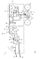
- FIG. 1 From a rail vehicle association consisting of at least two cars, only one end of a first car or a first power head is shown in FIG. 1 for reasons of scale. With respect to its free ends of the power cars, which are not coupled in normal operation, the train is symmetrical in construction, i. the first power head shown in Figure 1 corresponds to the second power car at the other end of the rail vehicle association.
- the rail vehicle association has a generally designated 1 electro-pneumatic braking device according to a preferred embodiment of the invention.
- the braking device 1 actuates a plurality of block brakes 2, which are arranged on bogies of the wagons of the rail vehicle association.
- the pad brake 2 of a bogie of the last or first carriage is shown in FIG.
- the pad brake 2 includes a with a within a brake cylinder 4 linearly movable actuator piston 6 coupled pad 8, which cooperates with a braking surface of a wheel 10 of the bogie.
- the brake pad 8 is fixed to a piston rod 12 of the adjusting piston 6, however, the adjusting piston 6 and the brake pad 8 and a brake linkage may be interposed in a known manner.
- a disc brake can be actuated by the brake cylinder 4.
- the brake cylinder 4 is preferably designed as a passive brake cylinder, that is, that the adjusting piston 6 is spring-loaded by a spring 14 in Bremszuspannides and by pressurizing a between the spring 14 facing away from the piston side and a wall of the brake cylinder 4 Pressure chamber 16 is brought into brake release position.
- the pressure chamber 16 of the brake cylinder 4 is vented through a vent valve 18 and a vent valve 20.
- the vent valve 20 is connected to a provided for pressure relief port 21 and the vent valve 18 to a pressure outlet 22 of a control valve assembly 24.
- a pressure input 26 of the control valve assembly 24 is in communication with a supply air tank 28.
- the control valve arrangement 24 has a pressure relief 30.
- the storage air tank 28 is also connected to a main air tank line HB ', which compressed air from a main air tank 32 leads, for example, is under a pressure of 10 bar.
- the braking device 1 is a so-called direct electro-pneumatic braking device, i. the brake cylinder 4 is aerated and vented directly via the electrical ventilation valves 18, 20, wherein the compressed air is removed from the reservoir pressure vessel 28, which is supplied by the main air reservoir line HB 'with compressed air.
- the vent valve 18 and the vent valve 20 are connected to a data bus, not shown in Figure 1 spanning the entire rail vehicle association, in particular a CAN bus Signafriv to these components controlled by a communicating with the data bus central control device on a brake or Soldering the driver based Bremsue worksssignale or Bremslettessignale Conssteuem.
- the vent valve 18 is preferably a normally open solenoid valve, in the vent valve 20 to a normally closed solenoid valve.
- the control valve assembly 24 serves as a subordinate level of safety in an accident, for example in the event of a failure of the on-board current, if due to a power failure, the electrical ventilation valves 18, 20 can no longer be operated.
- the control valve assembly 24 is capable of depending on a pending at a control input 34 pneumatic control pressure to generate a brake or release pressure at its pressure outlet 22 and by the then energize open vent valve 18 in the brake cylinder 4.
- the switching valve 36 is formed for example by an electrically operated solenoid valve, wherein it connects the pressure outlet 22 of the control valve assembly 26 and in the energized switching position the supply air tank 28 with the vent valve 18 in its de-energized switching position. Furthermore, the switching valve 36 and the vent valve 18, a solenoid valve 38 is interposed with a vent.
- the terminals 40, 42 thus serve to supply the brake device 1 with compressed air or pneumatic brake control signals in case of failure.
- braking devices always have a dual-line brake with a main air reservoir line HB and a main air line HL, which leads to a control pressure variable from the brake or release request signal, for example from 0 to 5 bar.
- the port 42 for the main air tank line HB and the port 40 for the main air line HL of the first car and the last car of the train are directly, i. directly or via very short pneumatic lines HB and HL, each with a coupling valve device 44 in connection, through which from the other rail vehicle approached control pressure and main reservoir pressure in the coupling valve means 44 intermediate section HB 'of the main air reservoir line HB on the one hand, a reservoir pressure and on the other hand also Control pressure for the control valve assembly 24 can be generated.
- the coupling valve device 44 preferably contains a relay valve 45.
- connection 42 for the main air reservoir line HB associated with the first carriage is connected to a pressure input 46 of the relay valve 45
- the connection 40 for the main air line HL assigned to the first carriage to a control input 48 of the relay valve 45 and a pressure outlet 50 is connected to a change-over valve device 51, which in turn is connected to the section HB 'of the main air reservoir line HB which is interposed between the coupling valve devices 44.
- the relay valve 45 has a pressure relief 56.
- the supply air tank 28 and the portion HB 'of the main air tank line HB is opened only to a supply air tank 28 back check valve 52 and a throttle 54 interposed.
- the control valve assembly 24 preferably also includes a relay valve 25.
- the structure of the two relay valves 25, 45, each with a spring-loaded double piston 58 and a spring-loaded double seat valve 60 is known per se, which is why will not be discussed here in detail.
- Both relay valves 25, 45 are preferably designed such that they depend from the at its control input 34, 48 pending control pressure hold the pressure at its pressure outlet 22.50, lower or increase. In particular, in the course of the pressure increase or decrease phase at their pressure outlet 22, 50, they can control a pressure proportional to the control pressure applied to their control input 34, 48, the proportionality factor being determined by the area ratio of the larger area A1 or A3 to the smaller one Surface A2 or A4 of the double piston 58 is formed.
- two load brake valves or a combination of a load brake valve and a relay valve may be used.
- the switching device 51 forms part of the coupling valve device 44 and includes a switching valve 61 which is connected between a switching position in which the pressure outlet 50 of the relay valve 45 is connected to a shut-off valve 63 and a switching position in which the pressure outlet 50 of the relay valve 45 of an air supply 65 of the first power head is switched, can be switched.
- the air supply 65 includes a compressed air tank 69 and a compressor 70, which fills the compressed air tank 69.
- the operation of the direct electro-pneumatic braking device 1 is as follows:
- a main air pressure in the amount of, for example, 10 bar and a control pressure in a range of, for example, are provided via the connection 42 for the main air line HB and the connection 40 for the main air line HL from another rail vehicle 0 to 5 bar introduced.
- the relay valve 45 forms from these two pressures a pressure proportional to the pressure in the main air line HL in a range of 0 to 10 bar at its pressure outlet 50.
- the switching valve 61 and the shut-off valve 63 are associated with the coupled to the other rail vehicle first power car Change-over valve device 51 either automatically or brought by the train driver in a switching position in which they through the pressure at the pressure outlet 50 of the relay valve 45 through the switching device 51 and in the section HB 'of the main air reservoir line HB, which there represents the control pressure for the relay valve 25 ,
- the switching device not assigned to the second, non-coupled drive train, not shown in FIG. 1, must disconnect the corresponding relay valve from the section HB 'so that it is not vented. This is accomplished, for example, by closing the corresponding shut-off valve.
- the prevailing in the section HB 'control pressure is then at the control input 34 of the relay valve 25, whereupon during the pressure increase or pressure drops at its pressure outlet 22, a proportional pressure is controlled, which via the de-energized switching valve 36, the normally closed by solenoid valve 38 and the also normally open vent valve 18 is controlled as brake or release pressure in the brake cylinder 4. Since the brake cylinder 4 is designed as a passive brake cylinder causes, for example, an increase in pressure in the pressure chamber 16, a release of the pad brake 2, so that the rail vehicle association can be towed with brakes released.
- a pressure reduction in the main air line HL during a pressure lowering phase causes a reduction of the relay valve 25 in the brake cylinder 4 pressure by venting the pressure chamber 16 via the pressure relief 30 of the relay valve 25.
- the switching devices 51 of both coupling valve devices 44 and in particular their switching valves 61 are in a switching position in which the respective air supply 65 through the open shut-off valve 63 with the section HB 'of the main air reservoir line HB in Connection stands while the pressure outputs 50 of the relay valves 45 are disconnected from this.
- control valve assembly 62 consists of a relay valve 64 as described above and an upstream control valve 66, which is adapted to a desired characteristic of the control pressure in the main air reservoir line HB '. Because the brake cylinder is in the present case an active brake cylinder, ie that a pressure increase in the pressure chamber 16 causes no loosening but a clamping of the pad brake 2 against the action of the spring 14 and a pressure reduction no tensioning but a release of the pad brake 2.
Landscapes
- Engineering & Computer Science (AREA)
- Transportation (AREA)
- Mechanical Engineering (AREA)
- Braking Systems And Boosters (AREA)
- Valves And Accessory Devices For Braking Systems (AREA)
- Braking Arrangements (AREA)
- Regulating Braking Force (AREA)
Claims (10)
- Train de véhicules ferroviaires composé d'au moins deux wagons, muni d'un système de frein électropneumatique direct (1), présentant les caractéristiques suivantes :(a) au moins un cylindre de frein pneumatique (4) est monté, qui est envisagé pour le raccord, d'un côté, moyennant d'au moins une seule soupape (18) à commande électrique à une sortie de pression (22) d'une unité à distributeur (24; 62) et, d'autre côté, moyennant d'au moins une autre soupape (20) à commande électrique à un connecteur (21), qui est montée à un connecteur (21) envisagé pour la décompression ;(b) une entrée de pression (26) de ladite unité à distributeur (24; 62) se trouve en communication avec un réservoir d'air comprimé (28), au dernier se trouvant en communication avec un conduite principale (HB');(c) ladite unité à distributeur (24; 62) est configurée pour la commande d'une pression de serrage ou de desserrage de frein dans ledit cylindre de frein (4) au cas de défaillance ou de défaut dans l'alimentation en courant en réponse à une pression de commande pneumatique régnant à une entrée de commande (34);
caractérisé en ce(d) qu'un raccord (40) respectif pour une conduite générale de frein (HL) est monté aux extrémités dirigées en sens opposés d'un premier wagon ou d'un premier engin moteur et d'un dernier wagon ou d'un deuxième engin moteur du train de véhicules ferroviaires pour l'alimentation d'une pression de commande pneumatique d'un autre véhicule ferroviaire, pendant qu'un raccord respectif (42) est monté pour ladite conduite principale (HB) pour l'alimentation d'une pression dans le réservoir principal d'air comprimé dudit autre véhicule ferroviaire;(e) en ce que, dans la zone desdites extrémités dirigées en sens opposés dudit premier wagon ou dudit premier engin moteur et du dernier wagon ou dudit deuxième engin moteur, un moyen à soupape de liaison supplémentaire respectif (44) est monté, moyennant duquel une pression de commande se peut engendrer pour ladite unité à distributeur (24; 62) à partir de l'alimentation en pression de commande arrivant dudit autre véhicule ferroviaire et de la pression dans le réservoir principal d'air comprimé dans ladite conduite principale (HB'), et en ce que(f) l'entrée de commande (34) de ladite unité à distributeur (24; 62) se trouve en communication avec une segment (HB') de ladite conduite principale (HB),m qui est interposé entre lesdits moyens à soupape de liaison (44). - Train de véhicules ferroviaires selon la revendication 1, caractérisé en ce que ledit moyen à soupape de liaison (44) est configuré d'une telle manière, que la pression de commande dans ledit segment (HB') de ladite conduite principale (HB) soit proportionnelle à la pression de commande alimentée.
- Train de véhicules ferroviaires selon la revendication 2, caractérisé en ce que ledit moyen à soupape de liaison (44) renferme une soupape de relais (45) ainsi qu'un moyen à soupape d'inversion (51).
- Train de véhicules ferroviaires selon la revendication 3, caractérisé en ce que ledit moyen d'inversion (51) est configuré pour le raccord dudit segment (HB') de ladite conduite principale (HB), qui est interposé entre lesdits moyens à soupape de liaison (44), à ladite soupape de relais (45) au cas de remorquage et à une alimentation en air comprimé (65) au cas de service normale.
- Train de véhicules ferroviaires selon une quelconque des revendications précédentes, caractérisé en ce que ladite unité à distributeur (24; 62) renferme une soupape de relais (25; 64).
- Train de véhicules ferroviaires selon une quelconque des revendications précédentes, caractérisé en ce que les raccords (42) pour ladite conduite principale (HB) et les raccords (40) pour ladite conduite générale de frein (HL) se trouvent en communication avec les moyens affectés à soupape (44) directement ou via des conduites pneumatiques très courtes.
- Train de véhicules ferroviaires selon une quelconque des revendications précédentes, caractérisé en ce que a soupape d'inversion (36) est interposée entre ladite sortie de pression (22) de ladite unité à distributeur (24; 62), ledit réservoir d'air comprimé (28) et ladite seule soupape (18), à cette soupape d'inversion reliant, au cas de défaillance, ladite sortie de pression (22) de ladite unité à distributeur (24; 62) et, dans tous les autres cas, ledit réservoir d'air comprimé (28) à ladite seule soupape (18).
- Train de véhicules ferroviaires selon une quelconque des revendications précédentes, caractérisé en ce qu'une soupape de non-retour (52), qui s'ouvre seulement vers ledit réservoir d'air comprimé (28), ainsi qu'une vanne d'étranglement (54) sont interposées entre ledit réservoir d'air comprimé (28) et ledit segment (HB') de ladite conduite principale (HB).
- Train de véhicules ferroviaires selon une quelconque des revendications précédentes, caractérisé en ce que ledit cylindre de frein pneumatique (4) est configuré en tant que cylindre de frein (4) actif ou passif.
- Train de véhicules ferroviaires selon une quelconque des revendications précédentes, caractérisé en ce que ladite seule soupape (18) est une soupape ouverte en absence de courant, pendant que ladite autre soupape (20) est une soupape fermée en absence de courant.
Priority Applications (1)
| Application Number | Priority Date | Filing Date | Title |
|---|---|---|---|
| SI200430293T SI1606154T1 (sl) | 2003-03-13 | 2004-03-12 | Iz vsaj dveh vagonov obstoječi vlak tirnih vozil z direktno elektropnevmatska zavorno pripravo |
Applications Claiming Priority (3)
| Application Number | Priority Date | Filing Date | Title |
|---|---|---|---|
| DE10310943 | 2003-03-13 | ||
| DE10310943 | 2003-03-13 | ||
| PCT/EP2004/002595 WO2004080775A1 (fr) | 2003-03-13 | 2004-03-12 | Ensemble de vehicules ferroviaires compose d'au moins deux wagons et equipe d'un systeme de freinage electro-pneumatique direct |
Publications (2)
| Publication Number | Publication Date |
|---|---|
| EP1606154A1 EP1606154A1 (fr) | 2005-12-21 |
| EP1606154B1 true EP1606154B1 (fr) | 2007-02-21 |
Family
ID=32945874
Family Applications (1)
| Application Number | Title | Priority Date | Filing Date |
|---|---|---|---|
| EP04719955A Expired - Lifetime EP1606154B1 (fr) | 2003-03-13 | 2004-03-12 | Ensemble de vehicules ferroviaires compose d au moins deux w agons et equipe d un systeme de freinage electro-pneumatique direct |
Country Status (5)
| Country | Link |
|---|---|
| EP (1) | EP1606154B1 (fr) |
| AT (1) | ATE354507T1 (fr) |
| DE (2) | DE502004002958D1 (fr) |
| SI (1) | SI1606154T1 (fr) |
| WO (1) | WO2004080775A1 (fr) |
Cited By (1)
| Publication number | Priority date | Publication date | Assignee | Title |
|---|---|---|---|---|
| EP4520604A1 (fr) * | 2023-09-11 | 2025-03-12 | Voith Patent GmbH | Procédé de démarrage d'un véhicule ferroviaire à plusieurs éléments |
Families Citing this family (9)
| Publication number | Priority date | Publication date | Assignee | Title |
|---|---|---|---|---|
| DE502006008956D1 (de) | 2006-12-13 | 2011-04-07 | Schweizerische Bundesbahnen Sbb | Bremsvorrichtung mit Notbrems- und Notbremsüberbrückungsfunktion |
| DE102014102882A1 (de) * | 2014-03-05 | 2015-09-10 | Knorr-Bremse Systeme für Schienenfahrzeuge GmbH | Bremsmodul für Güterwagen |
| DE102015224371A1 (de) * | 2015-12-04 | 2017-06-08 | Siemens Aktiengesellschaft | Druckluftbremseinrichtung für ein Schienenfahrzeug mit einer direkten, elektropneumatischen Bremse |
| DE102016205125A1 (de) * | 2016-03-29 | 2017-10-05 | Siemens Aktiengesellschaft | Bremssystem, Schienenfahrzeug mit einem Bremssystem sowie Verfahren zum Betrieb eines Bremssystems |
| US10994756B2 (en) | 2017-11-16 | 2021-05-04 | Westinghouse Air Brake Technologies Corporation | Electronically controlled brake overlay system for distributor valve |
| US11014585B2 (en) | 2017-11-16 | 2021-05-25 | Westinghouse Air Brake Technologies Corporation | ECP overlay system for W-type triple valve |
| US11027756B2 (en) | 2017-11-16 | 2021-06-08 | Westinghouse Air Brake Technologies Corporation | ECP overlay system for UIC-type distributor valve |
| CN109318880B (zh) * | 2017-12-13 | 2021-08-06 | 中车长春轨道客车股份有限公司 | 一种列车制动缓解系统及列车 |
| FR3093694B1 (fr) * | 2019-03-14 | 2021-03-19 | Faiveley Transp Amiens | Système de freinage ferroviaire comportant un dispositif afficheur d’un état d’un frein de service et/ou d’un état d’un frein de parking et véhicule ferroviaire pourvu d’un tel système |
Family Cites Families (5)
| Publication number | Priority date | Publication date | Assignee | Title |
|---|---|---|---|---|
| NL243488A (fr) * | 1958-09-18 | |||
| DE1179240B (de) * | 1963-08-02 | 1964-10-08 | Knorr Bremse Gmbh | Elektropneumatische Druckluftbremse fuer Schienenfahrzeuge |
| DE1191849B (de) * | 1963-11-23 | 1965-04-29 | Knorr Bremse Gmbh | Elektropneumatische Druckluftbremse fuer Schienenfahrzeuge |
| JPS51143213A (en) * | 1975-06-04 | 1976-12-09 | Japanese National Railways<Jnr> | Air break apparatus to actas break pipe and air reservoir pipe |
| DE2637506A1 (de) * | 1976-08-20 | 1978-02-23 | Knorr Bremse Gmbh | Elektropneumatische druckluftbremse fuer schienenfahrzeuge |
-
2004
- 2004-03-12 AT AT04719955T patent/ATE354507T1/de not_active IP Right Cessation
- 2004-03-12 EP EP04719955A patent/EP1606154B1/fr not_active Expired - Lifetime
- 2004-03-12 DE DE502004002958T patent/DE502004002958D1/de not_active Expired - Lifetime
- 2004-03-12 DE DE102004012100A patent/DE102004012100B4/de not_active Expired - Fee Related
- 2004-03-12 WO PCT/EP2004/002595 patent/WO2004080775A1/fr not_active Ceased
- 2004-03-12 SI SI200430293T patent/SI1606154T1/sl unknown
Cited By (1)
| Publication number | Priority date | Publication date | Assignee | Title |
|---|---|---|---|---|
| EP4520604A1 (fr) * | 2023-09-11 | 2025-03-12 | Voith Patent GmbH | Procédé de démarrage d'un véhicule ferroviaire à plusieurs éléments |
Also Published As
| Publication number | Publication date |
|---|---|
| EP1606154A1 (fr) | 2005-12-21 |
| DE502004002958D1 (de) | 2007-04-05 |
| WO2004080775A1 (fr) | 2004-09-23 |
| DE102004012100A1 (de) | 2004-10-07 |
| SI1606154T1 (sl) | 2007-08-31 |
| ATE354507T1 (de) | 2007-03-15 |
| DE102004012100B4 (de) | 2008-01-10 |
Similar Documents
| Publication | Publication Date | Title |
|---|---|---|
| EP3600991B1 (fr) | Frein à main électro-pneumatique avec tcv integré (commande scandinave) | |
| EP3755589B1 (fr) | Équipement électropneumatique d'un véhicule | |
| EP2331377B1 (fr) | Système de freinage de stationnement | |
| EP2055542B1 (fr) | Dispositif de frein actionné par un moyen de pression d'un véhicule sur rail doté d'un module de frein fixe produisant une pression contraire pour des freins de remorque | |
| DE69814188T2 (de) | Steuereinheit einer Druckluft-Zugbremsleitung | |
| DE102017006356A1 (de) | Elektro-Pneumatische Handbremse (EPH) mit integriertem TCV (Europäische Ansteuerung) | |
| DE102005054089C5 (de) | Steuergerät für eine Druckluftbremsanlage eines Kraftfahrzeugs | |
| DE69812738T2 (de) | Bremsleitung-Sensoreinheit | |
| EP3823868B1 (fr) | Module de frein de stationnement électropneumatique pourvu de soupapes à commande directe et d'un raccord de non-addition des efforts de freinage | |
| DE102017005980A1 (de) | Integriertes Anhängersteuermodul (TCV) mit externer elektropneumatischer Handbremseinheit (EPH) | |
| EP3414138B1 (fr) | Arrangement d'une vanne relais pour un système de freins pour véhicule pneumatique ou électrique-pneumatique | |
| EP4396052A1 (fr) | Unité de valve de frein de stationnement fiable dotée d'une soupape de dérivation | |
| DE102007038472A1 (de) | Ventilanordnung zur Steuerung einer Bremsanlage eines Anhängerfahrzeugs | |
| EP1606154B1 (fr) | Ensemble de vehicules ferroviaires compose d au moins deux w agons et equipe d un systeme de freinage electro-pneumatique direct | |
| DE3344301A1 (de) | Bremsanlage fuer ein anhaengerfahrzeug | |
| EP2082935B1 (fr) | Dispositif de freinage d'une remorque ayant au moins deux axes et comprenant un axe avant articulé d'une combinaison de remorque de véhicule de traction | |
| DE3344252A1 (de) | Anordnung in einer bremsanlage fuer schwere strassenfahrzeuge | |
| DE102012105136A1 (de) | Steuereinrichtung zur Steuerung der Bremsen einer Zugfahrzeug-Anhängerkombination | |
| DE102015121950A1 (de) | Verfahren zum Steuern einer elektro-pneumatischen Parkbremseinrichtung eines Fahrzeugs während der Fahrt als Hilfsbremse | |
| EP1366964B2 (fr) | Système de freinage de stationnement pour véhicules et procédé pour faire fonctionner | |
| DE10042215C5 (de) | Druckmittelbetätigte Fahrzeugbremsanlage mit redundanter Ansteuerung wenigstens eines Bremszylinders | |
| EP1069016B1 (fr) | Installation de freinage actionnée par moyen de pression | |
| EP1764276B1 (fr) | Système de freinage pneumatique pour véhicule automobile | |
| DE69900090T2 (de) | Bremssystem, insbesondere für sehr lange Züge | |
| EP1078832B1 (fr) | Dispositif de freinage, en particulier pour un véhicule industriel |
Legal Events
| Date | Code | Title | Description |
|---|---|---|---|
| PUAI | Public reference made under article 153(3) epc to a published international application that has entered the european phase |
Free format text: ORIGINAL CODE: 0009012 |
|
| 17P | Request for examination filed |
Effective date: 20051013 |
|
| AK | Designated contracting states |
Kind code of ref document: A1 Designated state(s): AT BE BG CH CY CZ DE DK EE ES FI FR GB GR HU IE IT LI LU MC NL PL PT RO SE SI SK TR |
|
| AX | Request for extension of the european patent |
Extension state: AL LT LV MK |
|
| DAX | Request for extension of the european patent (deleted) | ||
| GRAP | Despatch of communication of intention to grant a patent |
Free format text: ORIGINAL CODE: EPIDOSNIGR1 |
|
| GRAS | Grant fee paid |
Free format text: ORIGINAL CODE: EPIDOSNIGR3 |
|
| GRAA | (expected) grant |
Free format text: ORIGINAL CODE: 0009210 |
|
| AK | Designated contracting states |
Kind code of ref document: B1 Designated state(s): AT BE BG CH CY CZ DE DK EE ES FI FR GB GR HU IE IT LI LU MC NL PL PT RO SE SI SK TR |
|
| PG25 | Lapsed in a contracting state [announced via postgrant information from national office to epo] |
Ref country code: PL Free format text: LAPSE BECAUSE OF FAILURE TO SUBMIT A TRANSLATION OF THE DESCRIPTION OR TO PAY THE FEE WITHIN THE PRESCRIBED TIME-LIMIT Effective date: 20070221 Ref country code: NL Free format text: LAPSE BECAUSE OF FAILURE TO SUBMIT A TRANSLATION OF THE DESCRIPTION OR TO PAY THE FEE WITHIN THE PRESCRIBED TIME-LIMIT Effective date: 20070221 Ref country code: DK Free format text: LAPSE BECAUSE OF FAILURE TO SUBMIT A TRANSLATION OF THE DESCRIPTION OR TO PAY THE FEE WITHIN THE PRESCRIBED TIME-LIMIT Effective date: 20070221 Ref country code: FI Free format text: LAPSE BECAUSE OF FAILURE TO SUBMIT A TRANSLATION OF THE DESCRIPTION OR TO PAY THE FEE WITHIN THE PRESCRIBED TIME-LIMIT Effective date: 20070221 Ref country code: IE Free format text: LAPSE BECAUSE OF FAILURE TO SUBMIT A TRANSLATION OF THE DESCRIPTION OR TO PAY THE FEE WITHIN THE PRESCRIBED TIME-LIMIT Effective date: 20070221 |
|
| REG | Reference to a national code |
Ref country code: GB Ref legal event code: FG4D Free format text: NOT ENGLISH |
|
| REG | Reference to a national code |
Ref country code: CH Ref legal event code: EP |
|
| REF | Corresponds to: |
Ref document number: 502004002958 Country of ref document: DE Date of ref document: 20070405 Kind code of ref document: P |
|
| REG | Reference to a national code |
Ref country code: IE Ref legal event code: FG4D Free format text: LANGUAGE OF EP DOCUMENT: GERMAN |
|
| PG25 | Lapsed in a contracting state [announced via postgrant information from national office to epo] |
Ref country code: BG Free format text: LAPSE BECAUSE OF FAILURE TO SUBMIT A TRANSLATION OF THE DESCRIPTION OR TO PAY THE FEE WITHIN THE PRESCRIBED TIME-LIMIT Effective date: 20070521 Ref country code: SE Free format text: LAPSE BECAUSE OF FAILURE TO SUBMIT A TRANSLATION OF THE DESCRIPTION OR TO PAY THE FEE WITHIN THE PRESCRIBED TIME-LIMIT Effective date: 20070521 |
|
| PG25 | Lapsed in a contracting state [announced via postgrant information from national office to epo] |
Ref country code: ES Free format text: LAPSE BECAUSE OF FAILURE TO SUBMIT A TRANSLATION OF THE DESCRIPTION OR TO PAY THE FEE WITHIN THE PRESCRIBED TIME-LIMIT Effective date: 20070601 |
|
| PG25 | Lapsed in a contracting state [announced via postgrant information from national office to epo] |
Ref country code: PT Free format text: LAPSE BECAUSE OF FAILURE TO SUBMIT A TRANSLATION OF THE DESCRIPTION OR TO PAY THE FEE WITHIN THE PRESCRIBED TIME-LIMIT Effective date: 20070723 |
|
| NLV1 | Nl: lapsed or annulled due to failure to fulfill the requirements of art. 29p and 29m of the patents act | ||
| ET | Fr: translation filed | ||
| GBV | Gb: ep patent (uk) treated as always having been void in accordance with gb section 77(7)/1977 [no translation filed] |
Effective date: 20070221 |
|
| REG | Reference to a national code |
Ref country code: IE Ref legal event code: FD4D |
|
| PG25 | Lapsed in a contracting state [announced via postgrant information from national office to epo] |
Ref country code: SK Free format text: LAPSE BECAUSE OF FAILURE TO SUBMIT A TRANSLATION OF THE DESCRIPTION OR TO PAY THE FEE WITHIN THE PRESCRIBED TIME-LIMIT Effective date: 20070221 Ref country code: GB Free format text: LAPSE BECAUSE OF FAILURE TO SUBMIT A TRANSLATION OF THE DESCRIPTION OR TO PAY THE FEE WITHIN THE PRESCRIBED TIME-LIMIT Effective date: 20070221 |
|
| PLBE | No opposition filed within time limit |
Free format text: ORIGINAL CODE: 0009261 |
|
| STAA | Information on the status of an ep patent application or granted ep patent |
Free format text: STATUS: NO OPPOSITION FILED WITHIN TIME LIMIT |
|
| BERE | Be: lapsed |
Owner name: KNORR-BREMSE SYSTEME FUR SCHIENENFAHRZEUGE G.M.B. Effective date: 20070331 |
|
| PG25 | Lapsed in a contracting state [announced via postgrant information from national office to epo] |
Ref country code: BE Free format text: LAPSE BECAUSE OF NON-PAYMENT OF DUE FEES Effective date: 20070331 Ref country code: RO Free format text: LAPSE BECAUSE OF FAILURE TO SUBMIT A TRANSLATION OF THE DESCRIPTION OR TO PAY THE FEE WITHIN THE PRESCRIBED TIME-LIMIT Effective date: 20070221 |
|
| 26N | No opposition filed |
Effective date: 20071122 |
|
| PG25 | Lapsed in a contracting state [announced via postgrant information from national office to epo] |
Ref country code: MC Free format text: LAPSE BECAUSE OF NON-PAYMENT OF DUE FEES Effective date: 20070331 |
|
| PG25 | Lapsed in a contracting state [announced via postgrant information from national office to epo] |
Ref country code: IT Free format text: LAPSE BECAUSE OF FAILURE TO SUBMIT A TRANSLATION OF THE DESCRIPTION OR TO PAY THE FEE WITHIN THE PRESCRIBED TIME-LIMIT Effective date: 20070221 Ref country code: GR Free format text: LAPSE BECAUSE OF FAILURE TO SUBMIT A TRANSLATION OF THE DESCRIPTION OR TO PAY THE FEE WITHIN THE PRESCRIBED TIME-LIMIT Effective date: 20070522 |
|
| PG25 | Lapsed in a contracting state [announced via postgrant information from national office to epo] |
Ref country code: AT Free format text: LAPSE BECAUSE OF NON-PAYMENT OF DUE FEES Effective date: 20070312 |
|
| REG | Reference to a national code |
Ref country code: CH Ref legal event code: PL |
|
| PG25 | Lapsed in a contracting state [announced via postgrant information from national office to epo] |
Ref country code: CH Free format text: LAPSE BECAUSE OF NON-PAYMENT OF DUE FEES Effective date: 20080331 Ref country code: EE Free format text: LAPSE BECAUSE OF FAILURE TO SUBMIT A TRANSLATION OF THE DESCRIPTION OR TO PAY THE FEE WITHIN THE PRESCRIBED TIME-LIMIT Effective date: 20070221 Ref country code: LI Free format text: LAPSE BECAUSE OF NON-PAYMENT OF DUE FEES Effective date: 20080331 |
|
| PGFP | Annual fee paid to national office [announced via postgrant information from national office to epo] |
Ref country code: CZ Payment date: 20090302 Year of fee payment: 6 Ref country code: SI Payment date: 20090227 Year of fee payment: 6 |
|
| PG25 | Lapsed in a contracting state [announced via postgrant information from national office to epo] |
Ref country code: CY Free format text: LAPSE BECAUSE OF FAILURE TO SUBMIT A TRANSLATION OF THE DESCRIPTION OR TO PAY THE FEE WITHIN THE PRESCRIBED TIME-LIMIT Effective date: 20070221 |
|
| PG25 | Lapsed in a contracting state [announced via postgrant information from national office to epo] |
Ref country code: LU Free format text: LAPSE BECAUSE OF NON-PAYMENT OF DUE FEES Effective date: 20070312 |
|
| PG25 | Lapsed in a contracting state [announced via postgrant information from national office to epo] |
Ref country code: TR Free format text: LAPSE BECAUSE OF FAILURE TO SUBMIT A TRANSLATION OF THE DESCRIPTION OR TO PAY THE FEE WITHIN THE PRESCRIBED TIME-LIMIT Effective date: 20070221 Ref country code: HU Free format text: LAPSE BECAUSE OF FAILURE TO SUBMIT A TRANSLATION OF THE DESCRIPTION OR TO PAY THE FEE WITHIN THE PRESCRIBED TIME-LIMIT Effective date: 20070822 |
|
| PGFP | Annual fee paid to national office [announced via postgrant information from national office to epo] |
Ref country code: FR Payment date: 20090318 Year of fee payment: 6 |
|
| PG25 | Lapsed in a contracting state [announced via postgrant information from national office to epo] |
Ref country code: CZ Free format text: LAPSE BECAUSE OF NON-PAYMENT OF DUE FEES Effective date: 20100312 |
|
| REG | Reference to a national code |
Ref country code: SI Ref legal event code: KO00 Effective date: 20101018 |
|
| REG | Reference to a national code |
Ref country code: FR Ref legal event code: ST Effective date: 20101130 |
|
| PG25 | Lapsed in a contracting state [announced via postgrant information from national office to epo] |
Ref country code: FR Free format text: LAPSE BECAUSE OF NON-PAYMENT OF DUE FEES Effective date: 20100331 |
|
| PG25 | Lapsed in a contracting state [announced via postgrant information from national office to epo] |
Ref country code: SI Free format text: LAPSE BECAUSE OF NON-PAYMENT OF DUE FEES Effective date: 20100313 |
|
| PGFP | Annual fee paid to national office [announced via postgrant information from national office to epo] |
Ref country code: DE Payment date: 20230320 Year of fee payment: 20 |
|
| P01 | Opt-out of the competence of the unified patent court (upc) registered |
Effective date: 20230528 |
|
| REG | Reference to a national code |
Ref country code: DE Ref legal event code: R071 Ref document number: 502004002958 Country of ref document: DE |