EP1607155B1 - Transportbehälter - Google Patents
Transportbehälter Download PDFInfo
- Publication number
- EP1607155B1 EP1607155B1 EP05012892A EP05012892A EP1607155B1 EP 1607155 B1 EP1607155 B1 EP 1607155B1 EP 05012892 A EP05012892 A EP 05012892A EP 05012892 A EP05012892 A EP 05012892A EP 1607155 B1 EP1607155 B1 EP 1607155B1
- Authority
- EP
- European Patent Office
- Prior art keywords
- transport container
- transport
- lid
- emptying
- container
- Prior art date
- Legal status (The legal status is an assumption and is not a legal conclusion. Google has not performed a legal analysis and makes no representation as to the accuracy of the status listed.)
- Revoked
Links
- 239000007788 liquid Substances 0.000 claims abstract description 11
- XAGFODPZIPBFFR-UHFFFAOYSA-N aluminium Chemical compound [Al] XAGFODPZIPBFFR-UHFFFAOYSA-N 0.000 claims abstract description 8
- 229910052782 aluminium Inorganic materials 0.000 claims abstract description 8
- 239000000945 filler Substances 0.000 description 4
- 238000005266 casting Methods 0.000 description 2
Images

Classifications
-
- B—PERFORMING OPERATIONS; TRANSPORTING
- B22—CASTING; POWDER METALLURGY
- B22D—CASTING OF METALS; CASTING OF OTHER SUBSTANCES BY THE SAME PROCESSES OR DEVICES
- B22D41/00—Casting melt-holding vessels, e.g. ladles, tundishes, cups or the like
-
- B—PERFORMING OPERATIONS; TRANSPORTING
- B65—CONVEYING; PACKING; STORING; HANDLING THIN OR FILAMENTARY MATERIAL
- B65D—CONTAINERS FOR STORAGE OR TRANSPORT OF ARTICLES OR MATERIALS, e.g. BAGS, BARRELS, BOTTLES, BOXES, CANS, CARTONS, CRATES, DRUMS, JARS, TANKS, HOPPERS, FORWARDING CONTAINERS; ACCESSORIES, CLOSURES, OR FITTINGS THEREFOR; PACKAGING ELEMENTS; PACKAGES
- B65D88/00—Large containers
- B65D88/02—Large containers rigid
- B65D88/06—Large containers rigid cylindrical
- B65D88/08—Large containers rigid cylindrical with a vertical axis
Definitions
- the present invention relates to a transport container for transporting hot liquids, in particular liquid aluminum.
- transport containers For transporting liquid aluminum, transport containers with a capacity of about 4 to 5 tons of liquid aluminum have been used for many years. Such transport containers consist of an outer wall and an inner insulating layer. Access to the interior of the transport container is released via a lid. Examples of such transport containers are described in US 1,928,813, US 2003/0222381 A1 and EP 0 332 490 A1.
- Object of the present invention is to provide a transport container, which has the threefold capacity of the previously used container.
- a transport container for the transport of hot liquids in particular of liquid aluminum in the form of a cylinder, with an upwardly removable cover.
- This transport container has an outer wall and an inner insulating layer.
- the transport container has a substantially oval base surface and has a bottom outlet for emptying the transport container.
- the substantially oval base By using the substantially oval base, it is possible, in compliance with existing requirements, such as the prescribed Truck loading width and the passage heights under bridges, to provide a transport container, which has a capacity of at least 15 tons. In addition, the permissible total weight for road transport of 40 tons is not exceeded by means of the transport container according to the invention.
- the substantially oval base has a width of 2500 mm and a length of 3155 mm.
- the transport container in the lid at least one filler cap for filling the transport container.
- the emptying of the transport container according to the invention can be carried out by two different means.
- the transport container can be emptied via a casting spout.
- Such a casting spout is preferably arranged on one side of the transport container. For example, to let the liquid aluminum flow out through the spout, the transport container must be tilted.
- the emptying is carried out by means of a bottom outlet in the transport container.
- the bottom drain can be arranged, for example, at the edge between the base and the side wall of the transport container. To empty the transport container here only the bottom drain must be opened. Furthermore, tilting of the transport container is possible in order to empty it, which depends on the particular application.
- the bottom outlet is located at the lowest point of the interior of the transport container.
- the transport container in the lid on a bleed screw, which can be opened when emptying the transport container.
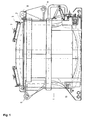
- the transport container 1 shown in Figure 1 has the shape of a cylinder and has a cover 2 arranged thereon.
- two filler caps 3 are arranged in the lid 2, via which the transport container 1 can be filled with liquid aluminum.
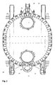
- FIG. 2 shows a plan view of the transport container 1 shown in FIG. 1.
- This view also shows the filler cap 3 in the lid 2 of the transport container 1.
- this view shows the pouring spout 4 with which the transport container 1 can be emptied.
- the pouring spout 4 is arranged on one side of the transport container 1 and has a lid with which the opening of the pouring spout can be closed. A detailed view of this pouring spout 4 is shown again in FIG.
- FIG. 4 shows another possibility for emptying the transport container 1.
- This bottom outlet is opened and closed by a hydraulically operated arm.
- the insulating layer 6 can also be seen in each case, with which the transport container 1 can be lined on the inside.
- the transport container 1 has in the cover 2 and a vent screw 7, which is arranged in the present embodiment of the filler cap 3.
- the transport container 1 also has transport eyelets 8 with which the transport container 1 can be transported, for example by means of a crane.
- the transport container has bolts 9 which can be used for emptying the transport container 1 via the spout 4. With the help of the holes 10 on the underside of the transport container 1 this can be fastened for example on a truck semi-trailer by means of bolts.
Landscapes
- Engineering & Computer Science (AREA)
- Mechanical Engineering (AREA)
- Details Of Rigid Or Semi-Rigid Containers (AREA)
- Packages (AREA)
- Transition And Organic Metals Composition Catalysts For Addition Polymerization (AREA)
- Control Of Driving Devices And Active Controlling Of Vehicle (AREA)
- Casting Support Devices, Ladles, And Melt Control Thereby (AREA)
Description
- Die vorliegende Erfindung betrifft einen Transportbehälter zum Transport von heißen Flüssigkeiten, insbesondere von flüssigem Aluminium.
- Zum Transport von flüssigem Aluminium werden schon seit vielen Jahren Transportbehälter mit einem Fassungsvermögen von etwa 4 bis 5 Tonnen flüssigen Aluminiums verwendet. Derartige Transportbehälter bestehen aus einer Außenwand und einer innen liegenden Isolierschicht. Der Zugang zu dem Innenraum des Transportbehälters wird über einen Deckel freigegeben. Beispiele für derartige Transportbehälter sind in US 1,928,813, US 2003/0222381 A1 und EP 0 332 490 A1 beschrieben.
- Aufgabe der vorliegenden Erfindung ist es, einen Transportbehälter bereit zu stellen, der dass dreifache Fassungsvermögen der bisher eingesetzten Behälter aufweist.
- Erfindungsgemäß wird die Aufgabe durch einen Transportbehälter zum Transport von heißen Flüssigkeiten, insbesondere von flüssigem Aluminium in Form eines Zylinders, mit einem nach oben abnehmbaren Deckel gelöst. Dieser Transportbehälter weist eine Außenwand und eine innen liegende Isolierschicht auf. Erfindungsgemäß verfügt der Transportbehälter über eine im Wesentlichen ovale Grundfläche und weist einen Bodenablass zum Entleeren des Transportbehälters auf.
- Durch die Verwendung der im Wesentlichen ovalen Grundfläche ist es möglich, unter Einhaltung von bestehenden Vorgaben, wie beispielsweise die vorgeschriebene LKW-Ladebreite und die Durchfahrtshöhen unter Brücken, einen Transportbehälter bereit zu stellen, der ein Fassungsvermögen von mindestens 15 Tonnen aufweist. Außerdem wird mit Hilfe des erfindungsgemäßen Transportbehälters das zulässige Gesamtgewicht für Straßentransport von 40 Tonnen nicht überschritten.
- Vorzugsweise weist die im Wesentlichen ovale Grundfläche eine Breite von 2500 mm und eine Länge von 3155 mm auf. In einer weiter bevorzugten Ausführungsform weist der Transportbehälter in dem Deckel mindestens einen Einfülldeckel zum Befüllen des Transportbehälters auf. Das Entleeren des erfindungsgemäßen Transportbehälters kann mit zwei verschiedenen Mitteln durchgeführt werden. Gemäß einer bevorzugten Ausführungsform der Erfindung kann der Transportbehälter über eine Gießschnauze entleert werden. Eine derartige Gießschnauze ist vorzugsweise an einer Seite des Transportbehälters angeordnet. Um beispielsweise das flüssige Aluminium durch die Gießschnauze herausfließen zu lassen, muss der Transportbehälter gekippt werden. Gemäß der Erfindung wird das Entleeren mit Hilfe eines Bodenablasses in dem Transportbehälter durchgeführt. Hierbei handelt es sich um eine Öffnung im unteren Bereich, vorzugsweise in der Grundfläche des Transportbehälters, die mit Hilfe eines Stopfens verschlossen werden kann. Alternativ kann der Bodenablass beispielsweise an der Kante zwischen der Grundfläche und der Seitenwand des Transportbehälters angeordnet sein. Zum Entleeren des Transportbehälters muss hier lediglich der Bodenablass geöffnet werden. Des Weiteren ist ein Kippen des Transportbehälters möglich, um diesen zu entleeren, welches vom jeweiligen Anwendungsfall abhängig ist. Vorzugsweise ist der Bodenablass am tiefsten Punkt des Innenraums des Transportbehälters angeordnet.
- In einer weiter bevorzugten Ausführungsform weist der Transportbehälter in dem Deckel eine Entlüftungsschraube auf, die beim Entleeren des Transportbehälters geöffnet werden kann.
- Im folgenden wird ein Ausführungsbeispiel der Erfindung anhand der beigefügten Zeichnungen erläutert, in denen
- Figur 1
- eine Seitenansicht des erfindungsgemäßen Transportbehälters zeigt,
- Figur 2
- eine Draufsicht des erfindungsgemäßen Transportbehälters zeigt,
- Figur 3
- eine Ausführungsform der Gießschnauze des Transportbehälters zeigt und
- Figur 4
- eine Ausführungsform der Bodenablassöffnung des Transportbehälters zeigt.
- Der in Figur 1 dargestellte Transportbehälter 1 hat die Form eines Zylinders und weist einen darauf angeordneten Deckel 2 auf. Im vorliegenden Ausführungsbeispiel sind in dem Deckel 2 zwei Einfülldeckel 3 angeordnet, über die der Transportbehälter 1 mit flüssigem Aluminium befüllt werden kann.
- Figur 2 zeigt eine Draufsicht des in Figur 1 gezeigten Transportbehälters 1. Diese Ansicht zeigt auch die Einfülldeckel 3 in dem Deckel 2 des Transportbehälters 1. Außerdem zeigt diese Ansicht die Gießschnauze 4 mit der der Transportbehälter 1 entleert werden kann. In der vorliegenden Ausführungsform ist die Gießschnauze 4 an einer Seite des Transportbehälters 1 angeordnet und weist einen Deckel auf, mit der die Öffnung der Gießschnauze verschlossen werden kann. Eine Detailansicht dieser Gießschnauze 4 ist in Figur 3 noch einmal wiedergegeben.
- Figur 4 zeigt eine weitere Möglichkeit den Transportbehälter 1 zu entleeren. Hierbei handelt es sich um den Bodenablass 5, der aus einer Öffnung besteht, die mit Hilfe eines Stopfens verschlossen werden kann. Das Öffnen und Schließen dieses Bodenablasses erfolgt über einen hydraulisch betriebenen Arm.
- In Figur 3 und Figur 4 ist auch jeweils die Isolierschicht 6 zu sehen, mit der der Transportbehälter 1 innen verkleidet sein kann.
- Der Transportbehälter 1 weist in dem Deckel 2 auch eine Entlüftungsschraube 7 auf, die in dem vorliegenden Ausführungsbeispiel an dem Einfülldeckel 3 angeordnet ist.
- Der Transportbehälter 1 verfügt darüber hinaus über Transportösen 8 mit denen der Transportbehälter 1 beispielsweise mit Hilfe eines Krans transportiert werden kann. Darüber hinaus verfügt der Transportbehälter über Bolzen 9 die für das Entleeren des Transportbehälters 1 über die Gießschnauze 4 verwendet werden können. Mit Hilfe der Bohrungen 10 an der Unterseite des Transportbehälters 1 kann dieser beispielsweise auf einem LKW-Auflieger mit Hilfe von Bolzen befestigt werden.
Claims (6)
- Transportbehälter (1) zum Transport von heißen Flüssigkeiten, insbesondere von flüssigem Aluminium, in Form eines Zylinders mit einem nach oben abnehmbaren Deckel (2), wobei der Transportbehälter (1) eine Außenwand, eine innen liegende Isolierschicht und eine im wesentlichen ovale Grundfläche aufweist
dadurch gekennzeichnet, dass
der Transportbehälter (1) einen Bodenablass (5) zum Entleeren des Transportbehälters (1) aufweist. - Transportbehälter (1) nach dem vorhergehenden Anspruch, dadurch gekennzeichnet, dass die im wesentlichen ovale Grundfläche eine Breite von 2500 mm und eine Länge von 3650 mm aufweist.
- Transportbehälter (1) nach einem der vorhergehenden Ansprüche, dadurch gekennzeichnet, dass der Transportbehälter (1) ein Fassungsvermögen von mindestens 15 Tonnen aufweist.
- Transportbehälter (1) nach einem der vorhergehenden Ansprüche, dadurch gekennzeichnet, dass der Transportbehälter (1) in dem Deckel (2) mindestens einen Einfülldeckel (3) aufweist.
- Transportbehälter (1) nach einem der vorhergehenden Ansprüche, dadurch gekennzeichnet, dass der Transportbehälter (1) eine Gießschnauze (4) zum Entleeren des Transportbehälters (1) aufweist.
- Transportbehälter (1) nach einem der vorhergehenden Ansprüche, dadurch gekennzeichnet, dass der Transportbehälter (1) in dem Deckel (2) eine Entlüftungsschraube (7) aufweist, die beim Entleeren des Transportbehälters geöffnet wird.
Applications Claiming Priority (2)
| Application Number | Priority Date | Filing Date | Title |
|---|---|---|---|
| DE202004009448U DE202004009448U1 (de) | 2004-06-15 | 2004-06-15 | Transportbehälter |
| DE202004009448U | 2004-06-15 |
Publications (2)
| Publication Number | Publication Date |
|---|---|
| EP1607155A1 EP1607155A1 (de) | 2005-12-21 |
| EP1607155B1 true EP1607155B1 (de) | 2007-05-09 |
Family
ID=32892768
Family Applications (1)
| Application Number | Title | Priority Date | Filing Date |
|---|---|---|---|
| EP05012892A Revoked EP1607155B1 (de) | 2004-06-15 | 2005-06-15 | Transportbehälter |
Country Status (3)
| Country | Link |
|---|---|
| EP (1) | EP1607155B1 (de) |
| AT (1) | ATE361801T1 (de) |
| DE (2) | DE202004009448U1 (de) |
Family Cites Families (5)
| Publication number | Priority date | Publication date | Assignee | Title |
|---|---|---|---|---|
| US1928813A (en) * | 1931-08-25 | 1933-10-03 | William B Pollock Company | Ladle |
| FR2627714B1 (fr) * | 1988-02-26 | 1990-12-28 | Alusuisse France Sa | Poche de transport notamment de metaux liquides |
| DE9422446U1 (de) * | 1994-04-15 | 2002-08-29 | RAG AG, 45128 Essen | Behälter, insbesondere für den Einsatz im Bergbau Untertage |
| DE10050835C1 (de) * | 2000-10-05 | 2001-12-20 | Mannesmann Ag | Metallurgisches Gefäß und Verfahren zur Herstellung desselben |
| DE20100839U1 (de) * | 2001-01-16 | 2001-05-10 | Egon Evertz KG (GmbH & Co.), 42655 Solingen | Gefäß für metallurgische Zwecke |
-
2004
- 2004-06-15 DE DE202004009448U patent/DE202004009448U1/de not_active Expired - Lifetime
-
2005
- 2005-06-15 EP EP05012892A patent/EP1607155B1/de not_active Revoked
- 2005-06-15 DE DE502005000684T patent/DE502005000684D1/de not_active Revoked
- 2005-06-15 AT AT05012892T patent/ATE361801T1/de not_active IP Right Cessation
Also Published As
| Publication number | Publication date |
|---|---|
| DE502005000684D1 (de) | 2007-06-21 |
| DE202004009448U1 (de) | 2004-08-19 |
| EP1607155A1 (de) | 2005-12-21 |
| ATE361801T1 (de) | 2007-06-15 |
Similar Documents
| Publication | Publication Date | Title |
|---|---|---|
| DE2813350C2 (de) | Zwischenbehälter zur Verwendung beim Stranggießen | |
| DE69804647T2 (de) | Sackförmige innere verkleidung zur verwendung mit einer aüsseren struktur zum transportieren und lagern von schüttgut | |
| EP1294508B1 (de) | Feuerfeste giessrohreinheit für die anordnung am ausguss eines metallschmelze enthaltenden gefässes, insbesondere eines zwischenbehälters einer bandgiessanlage | |
| DE102011004286A1 (de) | Kippvorrichtung | |
| EP1607155A1 (de) | Transportbehälter | |
| EP3415461B1 (de) | Pfanne für ein anbaugerät oder einen dieses verwendenden gabelstaplers | |
| DE3422569A1 (de) | Silo mit kreisrundem grundriss fuer schuettgueter | |
| CH630033A5 (de) | Hub-kippvorrichtung zum entleeren von behaeltern in sammelbehaelter, insbesondere von muellbehaeltern in muellsammelfahrzeuge. | |
| DE69403749T2 (de) | Behälter | |
| DE19926045C2 (de) | Mischer | |
| DE69602328T2 (de) | Müllsammelfahrzeug | |
| CH401833A (de) | Vorrichtung zum Umschütten von schütt- und fliessbarem Material | |
| DE2533415C3 (de) | Behälter für Schüttgut | |
| DE4224829C2 (de) | Anordnung zum Entladen und gegebenenfalls Beladen von Güterwagen | |
| EP2910496A1 (de) | Vorrichtung zum Transport oder zur Lagerung von schüttbarem Gut, Verfahren zum Beladen der Vorrichtung und Fahrzeug umfassend eine derartige Vorrichtung | |
| DE3825184C2 (de) | ||
| DE2816205C2 (de) | Transportbehälter für schmelzflüssiges Metall | |
| DE621692C (de) | Lastwagen zum Befoerdern von Muell | |
| DE696498C (de) | Vorrichtung zum staubfreien Entleeren von mit Deckel versehenen Muellgefaessen in Sammelkaesten, z. B. Muellwagen | |
| AT200065B (de) | An Müllabfuhrwagen anzubringende Mülltonnenentleerungsvorrichtung | |
| DE3335515C2 (de) | Schüttcontainer | |
| AT158284B (de) | Drehbarer Deckelverschluß für Behälter, insbesondere für Futter-Silos. | |
| DE3925380A1 (de) | Muellpresse mit absetzkipperbehaelter | |
| DE2422757C3 (de) | Behälter für preßbares Gut, insbesondere Müllbehälter | |
| DE651836C (de) | Vorrichtung zum Entleeren von Muelltonnen in Muellwagen mittels einer im Muellwagen drehbar gelagerten Trommel |
Legal Events
| Date | Code | Title | Description |
|---|---|---|---|
| PUAI | Public reference made under article 153(3) epc to a published international application that has entered the european phase |
Free format text: ORIGINAL CODE: 0009012 |
|
| AK | Designated contracting states |
Kind code of ref document: A1 Designated state(s): AT BE BG CH CY CZ DE DK EE ES FI FR GB GR HU IE IS IT LI LT LU MC NL PL PT RO SE SI SK TR |
|
| AX | Request for extension of the european patent |
Extension state: AL BA HR LV MK YU |
|
| 17P | Request for examination filed |
Effective date: 20060518 |
|
| 17Q | First examination report despatched |
Effective date: 20060711 |
|
| AKX | Designation fees paid |
Designated state(s): AT BE BG CH CY CZ DE DK EE ES FI FR GB GR HU IE IS IT LI LT LU MC NL PL PT RO SE SI SK TR |
|
| 17Q | First examination report despatched |
Effective date: 20060711 |
|
| GRAP | Despatch of communication of intention to grant a patent |
Free format text: ORIGINAL CODE: EPIDOSNIGR1 |
|
| GRAS | Grant fee paid |
Free format text: ORIGINAL CODE: EPIDOSNIGR3 |
|
| GRAA | (expected) grant |
Free format text: ORIGINAL CODE: 0009210 |
|
| RAP1 | Party data changed (applicant data changed or rights of an application transferred) |
Owner name: ALERIS RECYCLING (GERMAN WORKS) GMBH |
|
| AK | Designated contracting states |
Kind code of ref document: B1 Designated state(s): AT BE BG CH CY CZ DE DK EE ES FI FR GB GR HU IE IS IT LI LT LU MC NL PL PT RO SE SI SK TR |
|
| PG25 | Lapsed in a contracting state [announced via postgrant information from national office to epo] |
Ref country code: FI Free format text: LAPSE BECAUSE OF FAILURE TO SUBMIT A TRANSLATION OF THE DESCRIPTION OR TO PAY THE FEE WITHIN THE PRESCRIBED TIME-LIMIT Effective date: 20070509 |
|
| REG | Reference to a national code |
Ref country code: GB Ref legal event code: FG4D Free format text: NOT ENGLISH |
|
| REG | Reference to a national code |
Ref country code: CH Ref legal event code: EP |
|
| REG | Reference to a national code |
Ref country code: IE Ref legal event code: FG4D Free format text: LANGUAGE OF EP DOCUMENT: GERMAN |
|
| REF | Corresponds to: |
Ref document number: 502005000684 Country of ref document: DE Date of ref document: 20070621 Kind code of ref document: P |
|
| PG25 | Lapsed in a contracting state [announced via postgrant information from national office to epo] |
Ref country code: SE Free format text: LAPSE BECAUSE OF FAILURE TO SUBMIT A TRANSLATION OF THE DESCRIPTION OR TO PAY THE FEE WITHIN THE PRESCRIBED TIME-LIMIT Effective date: 20070809 |
|
| PG25 | Lapsed in a contracting state [announced via postgrant information from national office to epo] |
Ref country code: ES Free format text: LAPSE BECAUSE OF FAILURE TO SUBMIT A TRANSLATION OF THE DESCRIPTION OR TO PAY THE FEE WITHIN THE PRESCRIBED TIME-LIMIT Effective date: 20070820 |
|
| PG25 | Lapsed in a contracting state [announced via postgrant information from national office to epo] |
Ref country code: IS Free format text: LAPSE BECAUSE OF FAILURE TO SUBMIT A TRANSLATION OF THE DESCRIPTION OR TO PAY THE FEE WITHIN THE PRESCRIBED TIME-LIMIT Effective date: 20070909 |
|
| GBT | Gb: translation of ep patent filed (gb section 77(6)(a)/1977) |
Effective date: 20070905 |
|
| NLV1 | Nl: lapsed or annulled due to failure to fulfill the requirements of art. 29p and 29m of the patents act | ||
| PG25 | Lapsed in a contracting state [announced via postgrant information from national office to epo] |
Ref country code: PL Free format text: LAPSE BECAUSE OF FAILURE TO SUBMIT A TRANSLATION OF THE DESCRIPTION OR TO PAY THE FEE WITHIN THE PRESCRIBED TIME-LIMIT Effective date: 20070509 |
|
| REG | Reference to a national code |
Ref country code: IE Ref legal event code: FD4D |
|
| EN | Fr: translation not filed | ||
| PG25 | Lapsed in a contracting state [announced via postgrant information from national office to epo] |
Ref country code: SI Free format text: LAPSE BECAUSE OF FAILURE TO SUBMIT A TRANSLATION OF THE DESCRIPTION OR TO PAY THE FEE WITHIN THE PRESCRIBED TIME-LIMIT Effective date: 20070509 Ref country code: CZ Free format text: LAPSE BECAUSE OF FAILURE TO SUBMIT A TRANSLATION OF THE DESCRIPTION OR TO PAY THE FEE WITHIN THE PRESCRIBED TIME-LIMIT Effective date: 20070509 Ref country code: PT Free format text: LAPSE BECAUSE OF FAILURE TO SUBMIT A TRANSLATION OF THE DESCRIPTION OR TO PAY THE FEE WITHIN THE PRESCRIBED TIME-LIMIT Effective date: 20071009 Ref country code: IE Free format text: LAPSE BECAUSE OF FAILURE TO SUBMIT A TRANSLATION OF THE DESCRIPTION OR TO PAY THE FEE WITHIN THE PRESCRIBED TIME-LIMIT Effective date: 20070509 Ref country code: MC Free format text: LAPSE BECAUSE OF NON-PAYMENT OF DUE FEES Effective date: 20070630 Ref country code: NL Free format text: LAPSE BECAUSE OF FAILURE TO SUBMIT A TRANSLATION OF THE DESCRIPTION OR TO PAY THE FEE WITHIN THE PRESCRIBED TIME-LIMIT Effective date: 20070509 Ref country code: BG Free format text: LAPSE BECAUSE OF FAILURE TO SUBMIT A TRANSLATION OF THE DESCRIPTION OR TO PAY THE FEE WITHIN THE PRESCRIBED TIME-LIMIT Effective date: 20070809 Ref country code: DK Free format text: LAPSE BECAUSE OF FAILURE TO SUBMIT A TRANSLATION OF THE DESCRIPTION OR TO PAY THE FEE WITHIN THE PRESCRIBED TIME-LIMIT Effective date: 20070509 |
|
| PLBI | Opposition filed |
Free format text: ORIGINAL CODE: 0009260 |
|
| PG25 | Lapsed in a contracting state [announced via postgrant information from national office to epo] |
Ref country code: LT Free format text: LAPSE BECAUSE OF FAILURE TO SUBMIT A TRANSLATION OF THE DESCRIPTION OR TO PAY THE FEE WITHIN THE PRESCRIBED TIME-LIMIT Effective date: 20070509 Ref country code: SK Free format text: LAPSE BECAUSE OF FAILURE TO SUBMIT A TRANSLATION OF THE DESCRIPTION OR TO PAY THE FEE WITHIN THE PRESCRIBED TIME-LIMIT Effective date: 20070509 |
|
| 26 | Opposition filed |
Opponent name: ALUMINIUMSCHMELZWERK OETINGER GMBH Effective date: 20080204 |
|
| PLAX | Notice of opposition and request to file observation + time limit sent |
Free format text: ORIGINAL CODE: EPIDOSNOBS2 |
|
| PGFP | Annual fee paid to national office [announced via postgrant information from national office to epo] |
Ref country code: BE Payment date: 20071114 Year of fee payment: 3 |
|
| PG25 | Lapsed in a contracting state [announced via postgrant information from national office to epo] |
Ref country code: IT Free format text: LAPSE BECAUSE OF FAILURE TO SUBMIT A TRANSLATION OF THE DESCRIPTION OR TO PAY THE FEE WITHIN THE PRESCRIBED TIME-LIMIT Effective date: 20070509 Ref country code: GR Free format text: LAPSE BECAUSE OF FAILURE TO SUBMIT A TRANSLATION OF THE DESCRIPTION OR TO PAY THE FEE WITHIN THE PRESCRIBED TIME-LIMIT Effective date: 20070810 |
|
| PG25 | Lapsed in a contracting state [announced via postgrant information from national office to epo] |
Ref country code: RO Free format text: LAPSE BECAUSE OF FAILURE TO SUBMIT A TRANSLATION OF THE DESCRIPTION OR TO PAY THE FEE WITHIN THE PRESCRIBED TIME-LIMIT Effective date: 20070509 |
|
| PLAF | Information modified related to communication of a notice of opposition and request to file observations + time limit |
Free format text: ORIGINAL CODE: EPIDOSCOBS2 |
|
| PG25 | Lapsed in a contracting state [announced via postgrant information from national office to epo] |
Ref country code: FR Free format text: LAPSE BECAUSE OF FAILURE TO SUBMIT A TRANSLATION OF THE DESCRIPTION OR TO PAY THE FEE WITHIN THE PRESCRIBED TIME-LIMIT Effective date: 20080104 |
|
| PG25 | Lapsed in a contracting state [announced via postgrant information from national office to epo] |
Ref country code: AT Free format text: LAPSE BECAUSE OF NON-PAYMENT OF DUE FEES Effective date: 20070615 |
|
| PLBB | Reply of patent proprietor to notice(s) of opposition received |
Free format text: ORIGINAL CODE: EPIDOSNOBS3 |
|
| BERE | Be: lapsed |
Owner name: ALERIS RECYCLING (GERMAN WORKS) G.M.B.H. Effective date: 20080630 |
|
| PG25 | Lapsed in a contracting state [announced via postgrant information from national office to epo] |
Ref country code: EE Free format text: LAPSE BECAUSE OF FAILURE TO SUBMIT A TRANSLATION OF THE DESCRIPTION OR TO PAY THE FEE WITHIN THE PRESCRIBED TIME-LIMIT Effective date: 20070509 |
|
| PG25 | Lapsed in a contracting state [announced via postgrant information from national office to epo] |
Ref country code: BE Free format text: LAPSE BECAUSE OF NON-PAYMENT OF DUE FEES Effective date: 20080630 |
|
| PG25 | Lapsed in a contracting state [announced via postgrant information from national office to epo] |
Ref country code: CY Free format text: LAPSE BECAUSE OF FAILURE TO SUBMIT A TRANSLATION OF THE DESCRIPTION OR TO PAY THE FEE WITHIN THE PRESCRIBED TIME-LIMIT Effective date: 20070509 |
|
| PG25 | Lapsed in a contracting state [announced via postgrant information from national office to epo] |
Ref country code: LU Free format text: LAPSE BECAUSE OF NON-PAYMENT OF DUE FEES Effective date: 20070615 |
|
| PG25 | Lapsed in a contracting state [announced via postgrant information from national office to epo] |
Ref country code: HU Free format text: LAPSE BECAUSE OF FAILURE TO SUBMIT A TRANSLATION OF THE DESCRIPTION OR TO PAY THE FEE WITHIN THE PRESCRIBED TIME-LIMIT Effective date: 20071110 Ref country code: TR Free format text: LAPSE BECAUSE OF FAILURE TO SUBMIT A TRANSLATION OF THE DESCRIPTION OR TO PAY THE FEE WITHIN THE PRESCRIBED TIME-LIMIT Effective date: 20070509 |
|
| PGFP | Annual fee paid to national office [announced via postgrant information from national office to epo] |
Ref country code: DE Payment date: 20090619 Year of fee payment: 5 Ref country code: GB Payment date: 20090610 Year of fee payment: 5 |
|
| REG | Reference to a national code |
Ref country code: CH Ref legal event code: PL |
|
| RDAF | Communication despatched that patent is revoked |
Free format text: ORIGINAL CODE: EPIDOSNREV1 |
|
| PG25 | Lapsed in a contracting state [announced via postgrant information from national office to epo] |
Ref country code: LI Free format text: LAPSE BECAUSE OF NON-PAYMENT OF DUE FEES Effective date: 20090630 Ref country code: CH Free format text: LAPSE BECAUSE OF NON-PAYMENT OF DUE FEES Effective date: 20090630 |
|
| RDAG | Patent revoked |
Free format text: ORIGINAL CODE: 0009271 |
|
| STAA | Information on the status of an ep patent application or granted ep patent |
Free format text: STATUS: PATENT REVOKED |
|
| 27W | Patent revoked |
Effective date: 20100221 |
|
| GBPR | Gb: patent revoked under art. 102 of the ep convention designating the uk as contracting state |
Effective date: 20100221 |