EP1607169A1 - Verfahren zur Reparatur eines Turbinenschaufelteils - Google Patents
Verfahren zur Reparatur eines Turbinenschaufelteils Download PDFInfo
- Publication number
- EP1607169A1 EP1607169A1 EP20050291213 EP05291213A EP1607169A1 EP 1607169 A1 EP1607169 A1 EP 1607169A1 EP 20050291213 EP20050291213 EP 20050291213 EP 05291213 A EP05291213 A EP 05291213A EP 1607169 A1 EP1607169 A1 EP 1607169A1
- Authority
- EP
- European Patent Office
- Prior art keywords
- blade
- damaged
- replacement
- dawn
- blade element
- Prior art date
- Legal status (The legal status is an assumption and is not a legal conclusion. Google has not performed a legal analysis and makes no representation as to the accuracy of the status listed.)
- Withdrawn
Links
- 238000000034 method Methods 0.000 title claims abstract description 41
- 238000005096 rolling process Methods 0.000 claims description 13
- 238000005422 blasting Methods 0.000 claims description 10
- 239000002184 metal Substances 0.000 claims description 8
- 229910052751 metal Inorganic materials 0.000 claims description 8
- 238000005520 cutting process Methods 0.000 claims description 7
- 238000003754 machining Methods 0.000 claims description 7
- 238000003801 milling Methods 0.000 claims description 6
- 238000000227 grinding Methods 0.000 claims description 3
- 238000003825 pressing Methods 0.000 claims 1
- 238000003466 welding Methods 0.000 abstract description 19
- 239000000463 material Substances 0.000 description 22
- 230000035882 stress Effects 0.000 description 20
- 230000008439 repair process Effects 0.000 description 13
- 230000006835 compression Effects 0.000 description 6
- 238000007906 compression Methods 0.000 description 6
- 238000005482 strain hardening Methods 0.000 description 4
- 239000011324 bead Substances 0.000 description 3
- 239000000470 constituent Substances 0.000 description 3
- 230000007547 defect Effects 0.000 description 3
- 230000000694 effects Effects 0.000 description 3
- 239000012530 fluid Substances 0.000 description 3
- 238000004519 manufacturing process Methods 0.000 description 3
- 239000007769 metal material Substances 0.000 description 3
- 238000005219 brazing Methods 0.000 description 2
- 238000005266 casting Methods 0.000 description 2
- 238000007689 inspection Methods 0.000 description 2
- 238000003701 mechanical milling Methods 0.000 description 2
- 229910001092 metal group alloy Inorganic materials 0.000 description 2
- 230000032683 aging Effects 0.000 description 1
- 229910045601 alloy Inorganic materials 0.000 description 1
- 239000000956 alloy Substances 0.000 description 1
- 230000001186 cumulative effect Effects 0.000 description 1
- 230000006866 deterioration Effects 0.000 description 1
- 238000010894 electron beam technology Methods 0.000 description 1
- 238000005429 filling process Methods 0.000 description 1
- 238000010438 heat treatment Methods 0.000 description 1
- 230000002706 hydrostatic effect Effects 0.000 description 1
- 238000013021 overheating Methods 0.000 description 1
- 239000000843 powder Substances 0.000 description 1
- 238000002360 preparation method Methods 0.000 description 1
- 230000003252 repetitive effect Effects 0.000 description 1
- 229910000679 solder Inorganic materials 0.000 description 1
- 230000003068 static effect Effects 0.000 description 1
- 239000000126 substance Substances 0.000 description 1
- WFKWXMTUELFFGS-UHFFFAOYSA-N tungsten Chemical compound [W] WFKWXMTUELFFGS-UHFFFAOYSA-N 0.000 description 1
- 229910052721 tungsten Inorganic materials 0.000 description 1
- 239000010937 tungsten Substances 0.000 description 1
Images


Classifications
-
- B—PERFORMING OPERATIONS; TRANSPORTING
- B23—MACHINE TOOLS; METAL-WORKING NOT OTHERWISE PROVIDED FOR
- B23P—METAL-WORKING NOT OTHERWISE PROVIDED FOR; COMBINED OPERATIONS; UNIVERSAL MACHINE TOOLS
- B23P6/00—Restoring or reconditioning objects
- B23P6/002—Repairing turbine components, e.g. moving or stationary blades, rotors
- B23P6/005—Repairing turbine components, e.g. moving or stationary blades, rotors using only replacement pieces of a particular form
-
- B—PERFORMING OPERATIONS; TRANSPORTING
- B23—MACHINE TOOLS; METAL-WORKING NOT OTHERWISE PROVIDED FOR
- B23P—METAL-WORKING NOT OTHERWISE PROVIDED FOR; COMBINED OPERATIONS; UNIVERSAL MACHINE TOOLS
- B23P9/00—Treating or finishing surfaces mechanically, with or without calibrating, primarily to resist wear or impact, e.g. smoothing or roughening turbine blades or bearings; Features of such surfaces not otherwise provided for, their treatment being unspecified
- B23P9/02—Treating or finishing by applying pressure, e.g. knurling
-
- C—CHEMISTRY; METALLURGY
- C21—METALLURGY OF IRON
- C21D—MODIFYING THE PHYSICAL STRUCTURE OF FERROUS METALS; GENERAL DEVICES FOR HEAT TREATMENT OF FERROUS OR NON-FERROUS METALS OR ALLOYS; MAKING METAL MALLEABLE, e.g. BY DECARBURISATION OR TEMPERING
- C21D7/00—Modifying the physical properties of iron or steel by deformation
- C21D7/02—Modifying the physical properties of iron or steel by deformation by cold working
- C21D7/04—Modifying the physical properties of iron or steel by deformation by cold working of the surface
- C21D7/08—Modifying the physical properties of iron or steel by deformation by cold working of the surface by burnishing or the like
-
- F—MECHANICAL ENGINEERING; LIGHTING; HEATING; WEAPONS; BLASTING
- F01—MACHINES OR ENGINES IN GENERAL; ENGINE PLANTS IN GENERAL; STEAM ENGINES
- F01D—NON-POSITIVE DISPLACEMENT MACHINES OR ENGINES, e.g. STEAM TURBINES
- F01D5/00—Blades; Blade-carrying members; Heating, heat-insulating, cooling or antivibration means on the blades or the members
- F01D5/005—Repairing methods or devices
-
- F—MECHANICAL ENGINEERING; LIGHTING; HEATING; WEAPONS; BLASTING
- F05—INDEXING SCHEMES RELATING TO ENGINES OR PUMPS IN VARIOUS SUBCLASSES OF CLASSES F01-F04
- F05D—INDEXING SCHEME FOR ASPECTS RELATING TO NON-POSITIVE-DISPLACEMENT MACHINES OR ENGINES, GAS-TURBINES OR JET-PROPULSION PLANTS
- F05D2230/00—Manufacture
- F05D2230/80—Repairing, retrofitting or upgrading methods
-
- Y—GENERAL TAGGING OF NEW TECHNOLOGICAL DEVELOPMENTS; GENERAL TAGGING OF CROSS-SECTIONAL TECHNOLOGIES SPANNING OVER SEVERAL SECTIONS OF THE IPC; TECHNICAL SUBJECTS COVERED BY FORMER USPC CROSS-REFERENCE ART COLLECTIONS [XRACs] AND DIGESTS
- Y02—TECHNOLOGIES OR APPLICATIONS FOR MITIGATION OR ADAPTATION AGAINST CLIMATE CHANGE
- Y02T—CLIMATE CHANGE MITIGATION TECHNOLOGIES RELATED TO TRANSPORTATION
- Y02T50/00—Aeronautics or air transport
- Y02T50/60—Efficient propulsion technologies, e.g. for aircraft
-
- Y—GENERAL TAGGING OF NEW TECHNOLOGICAL DEVELOPMENTS; GENERAL TAGGING OF CROSS-SECTIONAL TECHNOLOGIES SPANNING OVER SEVERAL SECTIONS OF THE IPC; TECHNICAL SUBJECTS COVERED BY FORMER USPC CROSS-REFERENCE ART COLLECTIONS [XRACs] AND DIGESTS
- Y10—TECHNICAL SUBJECTS COVERED BY FORMER USPC
- Y10T—TECHNICAL SUBJECTS COVERED BY FORMER US CLASSIFICATION
- Y10T29/00—Metal working
- Y10T29/49—Method of mechanical manufacture
- Y10T29/49316—Impeller making
- Y10T29/49318—Repairing or disassembling
-
- Y—GENERAL TAGGING OF NEW TECHNOLOGICAL DEVELOPMENTS; GENERAL TAGGING OF CROSS-SECTIONAL TECHNOLOGIES SPANNING OVER SEVERAL SECTIONS OF THE IPC; TECHNICAL SUBJECTS COVERED BY FORMER USPC CROSS-REFERENCE ART COLLECTIONS [XRACs] AND DIGESTS
- Y10—TECHNICAL SUBJECTS COVERED BY FORMER USPC
- Y10T—TECHNICAL SUBJECTS COVERED BY FORMER US CLASSIFICATION
- Y10T29/00—Metal working
- Y10T29/49—Method of mechanical manufacture
- Y10T29/49718—Repairing
- Y10T29/49721—Repairing with disassembling
- Y10T29/4973—Replacing of defective part
-
- Y—GENERAL TAGGING OF NEW TECHNOLOGICAL DEVELOPMENTS; GENERAL TAGGING OF CROSS-SECTIONAL TECHNOLOGIES SPANNING OVER SEVERAL SECTIONS OF THE IPC; TECHNICAL SUBJECTS COVERED BY FORMER USPC CROSS-REFERENCE ART COLLECTIONS [XRACs] AND DIGESTS
- Y10—TECHNICAL SUBJECTS COVERED BY FORMER USPC
- Y10T—TECHNICAL SUBJECTS COVERED BY FORMER US CLASSIFICATION
- Y10T29/00—Metal working
- Y10T29/49—Method of mechanical manufacture
- Y10T29/49718—Repairing
- Y10T29/49732—Repairing by attaching repair preform, e.g., remaking, restoring, or patching
-
- Y—GENERAL TAGGING OF NEW TECHNOLOGICAL DEVELOPMENTS; GENERAL TAGGING OF CROSS-SECTIONAL TECHNOLOGIES SPANNING OVER SEVERAL SECTIONS OF THE IPC; TECHNICAL SUBJECTS COVERED BY FORMER USPC CROSS-REFERENCE ART COLLECTIONS [XRACs] AND DIGESTS
- Y10—TECHNICAL SUBJECTS COVERED BY FORMER USPC
- Y10T—TECHNICAL SUBJECTS COVERED BY FORMER US CLASSIFICATION
- Y10T29/00—Metal working
- Y10T29/49—Method of mechanical manufacture
- Y10T29/49718—Repairing
- Y10T29/49732—Repairing by attaching repair preform, e.g., remaking, restoring, or patching
- Y10T29/49734—Repairing by attaching repair preform, e.g., remaking, restoring, or patching and removing damaged material
Definitions
- the present invention relates to repair methods metal dawn elements and, more generally, shaped elements metal blades generally having a sectional shape with a width effective which is substantially larger than its thickness.
- the current invention relates more particularly, but not exclusively, to aerodynamic blade elements used in turbomachines such as turbines, aircraft engines, and the like.
- blade elements such as turbines, jet engines, and equivalent.
- these dawn elements are Made of metal or special metal alloys, and can be globally expensive to manufacture, maintain, and repair.
- these blades are prone generally to damage due to aging and wear. They also occasionally experience damage due to external factors such as damage by a foreign body in jet aircraft engines, problems occurring during manufacture parts or during assembly, and defects in design.
- the damage may also include deformation thermal and mechanical damage caused by vibration during of operation, and damage caused by overheating during operation.
- the damage can be in the form, for example, of punctures, holes, cracks, and other defects that may be visible or no to the naked eye. Such damage must be dealt with quickly in such a way that it does not lead to serious problems such as a failure of general structure, which creates a high potential for damage to property and people.
- dawn disks which are sometimes called “blisks” in terms of occupation, and are sometimes also known in the trades under the name of "monobloc bladed discs"
- blisks in terms of occupation
- monobloc bladed discs the inability to perform local repairs becomes very expensive when it is appropriate to replace an entire blisk set.
- the repair processes who plan to separate a dawn from its hub are by definition incompatible with the blisk structure. As a result, an entire blisk can be discarded while only a few of its blades are damaged.
- US 5,584,662 discloses filling of a vacuum formed in a dawn using a brazing material similar to that constituting dawn. Laser shot blasting is then used to induce deep compressive residual stresses (that is, about 508 to 1270 micrometers) in the repaired area.
- US 6,568,077 also discloses a method of repair that includes machining a damaged area using a milling machine to create a notch, followed by filling the notch in a welding step, using a filling material in the form of powder or thread. Finally, the welded repaired part is machined to reconstitute appropriate shape characteristics. Laser shot blasting or other post-repair steps are not used according to this document because the shape and size of the notch, and the corresponding welding process, are chosen to avoid zones of maximum stress of the dawn.
- US 6,238,187 discloses a repair method in which a localized damaged area is cut out, for example, in a turbine blade. It is prepared a replacement part which is at less globally similar in size, shape, and mechanical characteristics to the part cut out. The replacement part is put in place and welded, and is then formatted, if necessary, to conform to the geometry overall of the original dawn. Finally, US 6,238,187 discloses that the laser shot blasting "must" be used to treat the weld seam and adjacent areas so as to develop residual stresses of compression in the area that thwart the residual voltage fields in the material caused by the welding step.
- the present invention relates to a generally to a method of repairing damage to a metal blade element which is more economical than the processes conventional conventions discussed above, in particular with regard to the use of laser shot blasting.
- the present invention comprises, in a manner general, cutting or otherwise removing a part damaged part of the blade element, replacing it with a part of replacing the removed part, welding the replacement part setting up, and at least browning the resulting weld bead, if this is the entire dawn element surface.
- Burnishing works advantageously cold material of the blade element in order to induce compressive stresses in the dawn element repaired. This is a particular feature of this invention that burnishing provides an effective alternative but economical laser shot blasting. These compression constraints thwart residual stresses in the blade element structure caused by the welding of the replacement part put in place.
- the replacement part has characteristics material that closely matches the material constituting the element dawn so that a mechanical behavior approximately corresponding can be obtained.
- Burnishing can be done with a conventional tool appropriate, including a tool having, for example and without limitation, a fixed burnishing surface or a moving burnishing surface.
- the mobile burnishing surface may be a roll element, such as, but not necessarily, a ball-supported element suitable for rolling freely (making, in fact, a burnishing tool).
- an area damaged localized a blade element is repaired by cutting a part of the blade element generally covering the extent of the area damaged, and then replacing the part cut by a part of replacement formed in a similar manner.
- This is usually advantageous in that it minimizes the amount of original material constitutive element removed from the blade element, thus helping to maintain a high level of part the original mechanical characteristics of the blade element.
- FIGs 1 (a) to 1 (f) are schematic side views of a generalized blade element 10, in particular a blade element used in a turbomachine, such as a turbojet engine.
- the blade member 10 is made from any metallic material appropriate, including metal alloys.
- the element of dawn 10, as this is illustrated, includes, for example, a foot 12 for the mounting of the blade member 10 in a disc (not shown) in a known manner, for example a dovetail assembly.
- a platform 14 extends into a generally transverse direction and can stumble against a platform corresponding to an adjacent dawn element when the dawn elements are mounted on a disc.
- a wing profile 16 extends outward from the foot 12 and the platform 14 in a known manner, and has a leading edge indicated in a general way in 18.
- the wing profile 16 can have any profile desired aerodynamics, the details of which are not relevant to the present invention.
- Figure 1 (a) shows two examples extremely schematics of dawn element damage: part of edge damaged driver 20, and a damaged surface portion 22.
- Damage to the wing profile 16 may occur for a variety of known reasons including and not limited to damage by a foreign body, mechanical fatigue caused by a cycle thermal and centrifugal forces during operation, design and / or manufacturing defects, and chemical deterioration caused by an operating environment. Shapes damage may also vary, including without limitation surface perforations (such as at Part 22), edge stitching (as at the portion of the leading edge portion), surface pits, radiated cracks, and elongated cracks. The damage can be visible to the eye, or may be invisible to the eye but detectable by conventional technical inspection, including, in particular, the inspection of acoustic or X-ray.
- zones 20 'and 22' correspond to at least overall in size and / or shape to the damaged parts.
- zones 20 'and 22' correspond to at least overall in size and / or shape to the damaged parts.
- discrete damaged parts relatively large or at least visible such as 20 and 22 are frequently associated with damage invisible or otherwise not quite obvious all around. Therefore, it is desirable to remove some of the wing profile material that surrounds damaged parts to treat this possibility.
- the shape of zones 20 'and 22' may also depend on and be chosen according to the fields of constraint present in a given dawn element 10. These fields of constraint can be identified using well design techniques known.
- Zones 20 'and 22' can be removed by any known method suitable for the materials and the working environment in question. Any reference to a "cut” or equivalent is deemed encompass any removal process appropriate for the structure and constituent material in question, including but not limited to herself. The cut itself is possible according to the present invention, but may in some cases have negative side effects on the remaining structure. Another example of an appropriate removal process is mechanical milling. Another example of an appropriate removal process is cutting by known methods which preferably limit the amount of heat applied to the material. Once zones 20 'and 22' are removed, voids 24 and 26 remain in the dawn element 10. It is desirable, according to the present invention, to remove the zones 20 'and 22' from a known and reproducible manner so that the geometries of the voids 24, 26 are known. This facilitates the use of parts of replacement, as discussed above. For example, CNC methods can be used from a known manner for controlling the aforementioned examples of milling or cutting process.
- Figure 1 (c) illustrates the provision of replacement parts 20 " and 22 "As discussed in US 6,238,187, more generally, the creation of the replacement parts 20 “and 22" is preferably coordinated with the process of cutting the zones 20 'and 22' of such that the replacement parts 20 "and 22" correspond to one generally speaking to the resulting voids 24, 26.
- the geometry of the zones 20 'and 22' can be predefined to correspond to the parts of predefined replacement 20 "and 22", respectively.
- the parts of replacement 20 “and 22” can for example be formed individually as replacement elements by known methods such as casting or casting of the same metallic material constituting the element As a variant, the replacement parts 20 “and 22" may be cut into another "twin" blade element intended specifically for to be cannibalized.
- Figure 1 (d) illustrates replacement parts 20 "and 22" installed in corresponding voids 24 and 26, respectively. He is at note that the replacement parts 20 "and 22" may be slightly oversized compared to voids 24 and 26 in one or more dimensions, in anticipation of a subsequent machining process. It is preferable, as a minimum, that replacement parts 20 "and 22" be oversized rather than undersized.
- the machining process posterior can include, for example, mechanical milling, grinding manual, or both.
- Replacement parts 20 "and 22" are then fixed in place relative to the blade element 10.
- the parts of replacement 20 "and 22" are fixed in place by a welding process such as, without limitation, electron beam welding or Tungsten arc gas welding.
- the welding of the replacement parts 20 "and 22" put in place usually creates a residual voltage stress in the structure, at least partially due to the thermal effects of welding. These tension stresses cause weakness in the welded area and a possibility of fatigue failure. Another source of material weakness is the case where the replacement parts are made from a material having properties that do not match the dawn element material original.
- the cold work is performed by browning the zone and / or welded portions adjacent thereto in order to induce desired residual compressive stresses.
- the term "burnishing" according to the present invention includes the more specific known concept of "deep rolling" (i.e., browning at relatively high loads, e.g. 100 to 400 bar (10 7 Pa). to 4x10 7 Pa). in particular, the deep rolling is known to provide significantly more cold working, for example, laser peening.
- constraints of residual compression is induced at a depth of about 300 to about 1000 micrometers in the blade element structure.
- residual compression stresses are induced at a depth of at less than 800 micrometers.
- Figure 1 (f) illustrates zones 36, 38 (defined by solid lines at 32, 34, respectively) on which a burnishing or deep rolling according to the present invention is carried out.
- the zones 36, 38 as illustrated in FIG. 1 (f) practically comprise all 20 "and 22" replacement parts, solder seams associated 28 and 30, and a relatively narrow area of the original blade element Adjacent to the weld seams 28 and 30.
- the burnishing is performed on both sides of the element dawn 10 according to the preceding considerations. More specifically, the Burnishing done on both sides can be done simultaneously at the same time using at least two burnishing tools provided on respective sides of the blade member 10. The burnishing tool according to the present invention is further discussed below.
- the shape and size of the part of the blade element 10 that is removed do not necessarily have to comply exactly with those of the damaged part of the blade element.
- one or more shapes predefined slices can be used, the predefinition of these shapes thus facilitating the preparation of the corresponding replacement parts.
- the cumulative extent of damage to the dawn element may be too large for localized repairs multiple as described above in connection with Figures 1 (a) to 1 (f). In this case, it may be necessary to replace a significant part of the wing profile of the blade element, as discussed in relation to the Figures 2 (a) to 2 (e).
- Figures 2 (a) to 2 (e) are also schematic views of side of a generalized blade element 100, in particular an element of dawn used in a turbomachine, such as a turbojet engine.
- the blade member 100 is preferably made from any metallic material, including alloys metallic, suitable for turbomachine applications.
- the element blade 100 includes, for example, a foot 120 for mounting the blade member 100 in a disk (not shown) of a known manner, for example a dovetail adjustment.
- a platform 140 extends in a generally transverse direction and can abut against a corresponding platform of an adjacent blade element when the Dawn elements are mounted on a disk.
- the wing profile 160 extends towards outside from foot 120 and platform 140 in a known manner, and a leading edge indicated generally in 180.
- the wing profile 160 may have any desired aerodynamic profile, the details of which are not not relevant to the present invention.
- Figure 2 (a) shows three examples very schematic of dawn element damage: part of edge damaged driver 200, a damaged surface portion 220, and a damaged tip portion 221.
- Figure 2 (b) illustrates a remaining structure when a substantial portion 223 (see Figure 2 (a)) of the wing profile 160 including the damaged parts 200, 220, 221 has been removed, by example by cutting or milling.
- Line 240 'at which the most of the wing profile 160 is removed is preferably a low stress location compared to the constraints presented in the wing profile.
- the element dawn 100 is here completely cut in a transverse direction by referred to direction A (see Figure 2 (a)) in which the element extends 100.
- FIG. 2 (b) there is shown the wing profile stub 240 comprising a cut surface 240 "on which a replacement part is then fixed.
- Figure 2 (c) illustrates the provision of a wing profile portion of 260.
- the part of replacement wing profile 260 is attached to the wing profile stub 240, again preferably by welding (such as beam welding of electrons) to form a weld bead 240.
- Friction welding inertia as this term is known in the field, can also be used to attach the replacement wing profile portion 260 to the stub wing profile 240 and is particularly intended for repairing structures of blisk.
- the replacement wing profile portion can also be slightly oversized (that is, thicker, wider, and / or large) compared to the wing profile stub 240.
- the part of oversized replacement wing profile would be machined in a way appropriate after being welded in place in order to comply with the original blade element configuration, similar to the process discussed and illustrated above in Figures 1 (d) and 1 (e). It is preferable that replacement wing profile portion be oversized rather than under dimensioned relative to the wing profile stub 240.
- an area 280 ( Figure 2 (e)) of the wing profile at or at least adjacent to the bead of 240 "weld is burnished or rolled deep in a manner similar to that described above with reference to Figs. 1 (a) to 1 (f).
- This induced browning residual compression stresses in the blade element in order to counteract the residual stress stress caused when welding the replacement wing profile portion 260 set up.
- he is important to cause cold work sufficient to reinforce the cord of 240 "weld and material structure to provide dawn repair sustainable and of good quality.
- compressive stresses residuals are induced at a depth of about 300 to about 1000 micrometers in the dawn element structure.
- the constraints residual compression is induced to a depth of at least 800 micrometers.
- burnishing or rolling performed according to the present invention can be performed with any what deep-rolling or deep rolling tool known as long as it can perform the desired level of hardening by cold working at depth appropriate.
- the chosen tool can be applied on a non-repetitive trajectory and / or without overlapping on the wing profile surface or it may be applied in a more random manner that may include trajectories that overlap one or more times.
- the trajectory along which the burnishing or deep rolling is achieved can be controlled and / or defined by known tool control methods, including, for example, computer numerical control (“CNC”) processes.
- CNC computer numerical control
- the pressure applied by the tool can be constant over the entire treated area, or it may vary selectively in a continuous manner or discontinuous.
- the tool can be equipped with a freely movable tip such a bearing link or other rolling pressure element, or although it may have a non-moving burnishing head, usually rounded configuration.
- burnishing tools and deep rolling ball are known in the state of the art and are described by for example, in US Pat. Nos. 4,947,668, 5,826,453 and 6,415,486, and in published patent application US 2002/0174528. These tools provide, for example, a ball element in the form of a base so that the ball is free to roll when the tool is moved relative to the surface that is browned (or, more precisely, pebbled).
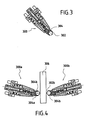
- Figure 3 illustrates, very schematically, an example of a burnishing tool 300 comprising a rolling ball element 302 held in a base 304.
- the element ball 302 can be, for example and without limitation, supported in a manner hydrostatic fluid under pressure to be freely mobile in the base 304, as is well known in the state of the art.
- a rotating roller element (not shown) or a blunt or rounded, fixed (ie, static) tip also be used.
- the force (ie the load) applied by the tool may depend on several factors, including the diameter of the ball element, the material of the ball element, and the fluid pressure supporting the fluid element. Strength may also depend on and be controlled by the manner in which the tool is mounted, for example, on a tool table, a robotic arm, etc.
- FIG. 4 illustrates, very schematically, a browning arrangement which allows browning on both sides.
- two tools of burnishing 300a, 300b are provided.
- Burnishing tools 300a, 300b have each a general structure similar to the tool 300 of FIG. example, or similar to any known burnishing tool, so a detailed explanation is omitted here.
- the tools 300a, 300b are mounted on a stirrup-shaped apparatus (not shown here) such that a generic blade element portion 306 is disposed between them.
- the respective ball elements 302a, 302b are oriented so that they oppose substantially on opposite sides of the part of blade element 306.
Landscapes
- Engineering & Computer Science (AREA)
- Mechanical Engineering (AREA)
- Chemical & Material Sciences (AREA)
- General Engineering & Computer Science (AREA)
- Crystallography & Structural Chemistry (AREA)
- Materials Engineering (AREA)
- Metallurgy (AREA)
- Organic Chemistry (AREA)
- Turbine Rotor Nozzle Sealing (AREA)
- Structures Of Non-Positive Displacement Pumps (AREA)
Applications Claiming Priority (2)
| Application Number | Priority Date | Filing Date | Title |
|---|---|---|---|
| FR0406467A FR2871399B1 (fr) | 2004-06-15 | 2004-06-15 | Procede de reparation d'un element d'aube |
| FR0406467 | 2004-06-15 |
Publications (1)
| Publication Number | Publication Date |
|---|---|
| EP1607169A1 true EP1607169A1 (de) | 2005-12-21 |
Family
ID=34946505
Family Applications (1)
| Application Number | Title | Priority Date | Filing Date |
|---|---|---|---|
| EP20050291213 Withdrawn EP1607169A1 (de) | 2004-06-15 | 2005-06-07 | Verfahren zur Reparatur eines Turbinenschaufelteils |
Country Status (4)
| Country | Link |
|---|---|
| US (1) | US20060277753A1 (de) |
| EP (1) | EP1607169A1 (de) |
| CA (1) | CA2509803C (de) |
| FR (1) | FR2871399B1 (de) |
Cited By (12)
| Publication number | Priority date | Publication date | Assignee | Title |
|---|---|---|---|---|
| EP1813686A1 (de) * | 2006-01-27 | 2007-08-01 | General Electric Company | Herstellung einer eine Struktur mit Oberflächendruckspannungen aufweisenden Oberfläche eines Gegenstandes |
| EP1914382A1 (de) * | 2006-10-20 | 2008-04-23 | Siemens Aktiengesellschaft | Verfahren zur Reparatur einer Turbinenschaufel |
| EP1986814A4 (de) * | 2006-01-09 | 2010-04-07 | Surface Technology Holdings | Verfahren zur verbesserung der eigenschaften einer reparierten komponente und dadurch verbesserte komponente |
| EP2018235A4 (de) * | 2006-04-07 | 2010-04-21 | Surface Technology Holdings | Oberflächenbehandlungsvorrichtung und -verfahren |
| WO2010028641A3 (de) * | 2008-09-13 | 2010-05-06 | Mtu Aero Engines Gmbh | Ersatzteil für eine gasturbinen-schaufel einer gasturbine, gasturbinen-schaufel sowie ein verfahren zur reparatur einer gasturbine-schaufel |
| CN102328183A (zh) * | 2011-09-13 | 2012-01-25 | 上海宝钢型钢有限公司 | 焊缝压延装置 |
| EP2187020A4 (de) * | 2008-02-14 | 2012-02-29 | Mitsubishi Heavy Ind Ltd | Verfahren zur reparatur einer turbinenrotorschaufel |
| ES2388410A1 (es) * | 2012-02-01 | 2012-10-15 | Plastic Repair System 2011, S.L. | Procedimiento de reparación de productos de plástico |
| WO2012140103A1 (de) * | 2011-04-12 | 2012-10-18 | Rolls-Royce Deutschland Ltd & Co Kg | Verfahren zur herstellung eines einstückigen rotorbereiches und einstückiger rotorbereich |
| WO2013113302A1 (de) * | 2012-02-02 | 2013-08-08 | Rolls-Royce Deutschland Ltd & Co Kg | Verfahren zur mechanischen randzonenverfestigung von bauteilen |
| US9427833B2 (en) | 2012-09-20 | 2016-08-30 | Rolls-Royce Deutschland Ltd & Co Kg | Rolling tool device |
| US9498856B2 (en) | 2012-09-20 | 2016-11-22 | Rolls-Royce Deutschland Ltd & Co Kg | Rolling tool device |
Families Citing this family (44)
| Publication number | Priority date | Publication date | Assignee | Title |
|---|---|---|---|---|
| DE50310894D1 (de) * | 2003-03-25 | 2009-01-22 | Siemens Ag | Verfahren und Vorrichtung zur Herstellung einer Turbinenkomponente |
| US7497677B1 (en) | 2003-09-08 | 2009-03-03 | Crain Enterprises, Inc. | Mold having modular submold |
| US7241405B1 (en) * | 2003-09-08 | 2007-07-10 | Crain Enterprises, Inc. | Method of renewing a mold block |
| US7500843B2 (en) * | 2004-09-08 | 2009-03-10 | Crain Enterprises, Inc. | Mold system kit |
| WO2007055864A2 (en) * | 2005-10-12 | 2007-05-18 | Surface Technology Holdings, Ltd | Improved integrally bladed rotating turbo machinery and method and apparatus for achieving the same |
| US20080032152A1 (en) * | 2006-08-04 | 2008-02-07 | Vaughn Glen A | Use of laser shock processing in oil & gas and petrochemical applications |
| US20080216300A1 (en) * | 2007-03-06 | 2008-09-11 | United Technologies Corporation | Splitter fairing repair |
| DE102007019949A1 (de) * | 2007-04-27 | 2008-10-30 | Mtu Aero Engines Gmbh | Halbzeug zum Erzeugen einer reparierten Schaufel für eine Gasturbine und Reparaturverfahren für die Reparatur einer Schaufel für eine Gasturbine |
| US20080267775A1 (en) * | 2007-04-30 | 2008-10-30 | General Electric Company | Nozzle segments and method of repairing the same |
| US20090000101A1 (en) * | 2007-06-29 | 2009-01-01 | United Technologies Corp. | Methods for Repairing Gas Turbine Engines |
| US9765622B2 (en) * | 2007-09-12 | 2017-09-19 | United Technologies Corporation | Methods for performing gas turbine engine casing repairs and repaired cases |
| US20090071002A1 (en) * | 2007-09-18 | 2009-03-19 | United Technologies Corp. | Methods for Repairing Gas Turbine Engine Components |
| US20090185908A1 (en) * | 2008-01-21 | 2009-07-23 | Honeywell International, Inc. | Linear friction welded blisk and method of fabrication |
| ATE502720T1 (de) * | 2008-04-09 | 2011-04-15 | Alstom Technology Ltd | VERFAHREN ZUR REPARATUR DER HEIßGASKOMPONENTE EINER GASTURBINE |
| US8257039B2 (en) | 2008-05-02 | 2012-09-04 | United Technologies Corporation | Gas turbine engine case with replaced flange and method of repairing the same using cold metal transfer |
| US8240042B2 (en) * | 2008-05-12 | 2012-08-14 | Wood Group Heavy Industrial Turbines Ag | Methods of maintaining turbine discs to avert critical bucket attachment dovetail cracks |
| US20090313823A1 (en) * | 2008-06-24 | 2009-12-24 | Todd Jay Rockstroh | Imparting deep compressive residual stresses into a gas turbine engine airfoil peripheral repair weldment |
| US20090320288A1 (en) * | 2008-06-30 | 2009-12-31 | Caterpillar Inc. | Method for repairing a turbine |
| US8651393B2 (en) * | 2010-03-26 | 2014-02-18 | Holland, L.P. | Repair insert for repairing metallic structure |
| DE102011080187A1 (de) * | 2011-08-01 | 2013-02-07 | Siemens Aktiengesellschaft | Verfahren zum Erzeugen einer Schaufel für eine Strömungskraftmaschine und Schaufel für eine Strömungskraftmaschine |
| US8959738B2 (en) * | 2012-03-21 | 2015-02-24 | General Electric Company | Process of repairing a component, a repair tool for a component, and a component |
| US9863249B2 (en) * | 2012-12-04 | 2018-01-09 | Siemens Energy, Inc. | Pre-sintered preform repair of turbine blades |
| US10273816B2 (en) * | 2013-02-12 | 2019-04-30 | United Technologies Corporation | Wear pad to prevent cracking of fan blade |
| EP2781691A1 (de) * | 2013-03-19 | 2014-09-24 | Alstom Technology Ltd | Verfahren zur Neukonditionierung für einen Heißgaspfad einer Gasturbine |
| RU2548848C1 (ru) * | 2013-10-29 | 2015-04-20 | Федеральное государственное бюджетное образовательное учреждение высшего профессионального образования "Ульяновский государственный технический университет" | Способ поверхностного пластического деформирования |
| RU2558311C2 (ru) * | 2013-10-29 | 2015-07-27 | Федеральное государственное бюджетное образовательное учреждение высшего профессионального образования "Ульяновский государственный технический университет" | Способ обработки маложестких заготовок сложнопрофильных деталей |
| US20150132143A1 (en) * | 2013-11-11 | 2015-05-14 | Gerald J. Bruck | Welding process and reduced restraint weld joint |
| CN104526253A (zh) * | 2015-01-09 | 2015-04-22 | 江苏龙胜机床制造有限公司 | 四辊卷板机机架裂纹的焊接修复方法 |
| CN104526254A (zh) * | 2015-01-09 | 2015-04-22 | 江苏龙胜机床制造有限公司 | 四辊卷板机机架断裂的焊接修复方法 |
| US20160375522A1 (en) * | 2015-06-26 | 2016-12-29 | Siemens Energy, Inc. | Welding method for superalloys |
| DE102015215027A1 (de) * | 2015-08-06 | 2017-02-09 | Siemens Aktiengesellschaft | Verfahren zum Ausbessern von Schäden eines Werkstücks und Vorrichtung |
| US10113531B2 (en) * | 2015-08-26 | 2018-10-30 | General Electric Company | Methods for repairing wind turbine rotor blades |
| JP6541742B2 (ja) * | 2017-10-13 | 2019-07-10 | 三菱重工業株式会社 | 風車翼の補修方法 |
| CN108188508B (zh) * | 2017-11-29 | 2019-03-05 | 重庆运城制版有限公司 | 一种修版方法 |
| ES2935395T3 (es) * | 2019-03-21 | 2023-03-06 | Siemens Gamesa Renewable Energy As | Método de reparación de un cordón de larguero dañado de una pala de turbina eólica de una turbina eólica |
| FR3097641B1 (fr) | 2019-06-20 | 2021-12-10 | Safran | Procédé de fabrication d'une éprouvette de caractérisation |
| CN114207250B (zh) * | 2019-07-30 | 2024-03-08 | 西门子能源美国公司 | 用于修复高温燃气涡轮部件的系统和方法 |
| US11828190B2 (en) | 2021-11-18 | 2023-11-28 | General Electric Company | Airfoil joining apparatus and methods |
| CN114083224B (zh) * | 2021-11-26 | 2022-11-15 | 国网四川省电力公司映秀湾水力发电总厂 | 一种混流式水轮机固定导叶的修复方法 |
| US11814979B1 (en) * | 2022-09-21 | 2023-11-14 | Rtx Corporation | Systems and methods of hybrid blade tip repair |
| GB2624020B (en) * | 2022-11-04 | 2025-07-02 | Gkn Aerospace Sweden Ab | IBR blade repair |
| CN115635243B (zh) * | 2022-11-14 | 2024-04-26 | 中国航发沈阳黎明航空发动机有限责任公司 | 一种轮辐式进气机匣叶片更换修理方法 |
| CN117548995B (zh) * | 2023-11-15 | 2026-03-06 | 中国航发南方工业有限公司 | 航空发动机用风扇工作环槽孔装夹加工方法 |
| CN120816257B (zh) * | 2025-05-06 | 2026-01-23 | 山东能源装备集团奔牛再制造有限公司 | 一种针对矿用采煤运输设备关键件的智能化修复方法 |
Citations (7)
| Publication number | Priority date | Publication date | Assignee | Title |
|---|---|---|---|---|
| US5826453A (en) * | 1996-12-05 | 1998-10-27 | Lambda Research, Inc. | Burnishing method and apparatus for providing a layer of compressive residual stress in the surface of a workpiece |
| US6238187B1 (en) * | 1999-10-14 | 2001-05-29 | Lsp Technologies, Inc. | Method using laser shock peening to process airfoil weld repairs pertaining to blade cut and weld techniques |
| EP1175956A1 (de) * | 2000-07-27 | 2002-01-30 | General Electric Company | Metallischer Artikel mit integralem kompressierten Ring am Ende und Herstellungsverfahren |
| US20020037219A1 (en) * | 2000-09-22 | 2002-03-28 | Webster John R. | Gas turbine engine rotor blades |
| US6415486B1 (en) * | 2000-03-01 | 2002-07-09 | Surface Technology Holdings, Ltd. | Method and apparatus for providing a residual stress distribution in the surface of a part |
| WO2003039804A1 (en) * | 2001-11-02 | 2003-05-15 | The Boeing Company | Apparatus and method for forming weld joints having compressive residual stress patterns |
| WO2004030858A1 (de) * | 2002-09-28 | 2004-04-15 | Mtu Aero Engines Gmbh | Vorrichtung und verfahren zur oberflächenbearbeitung von werkstücken |
Family Cites Families (9)
| Publication number | Priority date | Publication date | Assignee | Title |
|---|---|---|---|---|
| US623187A (en) * | 1899-04-18 | Apparatus for | ||
| US3650635A (en) * | 1970-03-09 | 1972-03-21 | Chromalloy American Corp | Turbine vanes |
| GB2198667B (en) * | 1986-12-20 | 1991-08-07 | Refurbished Turbine Components | Parts for and methods of repairing machines |
| DE8809823U1 (de) * | 1988-08-02 | 1988-10-06 | Wilhelm Hegenscheidt Gmbh, 5140 Erkelenz | Walzwerkzeug |
| EP0353427B1 (de) * | 1988-08-02 | 1992-11-11 | Wilhelm Hegenscheidt Gesellschaft mbH | Walzeinheit |
| GB8904988D0 (en) * | 1989-03-04 | 1989-04-19 | Refurbished Turbine Components | Turbine blade repair |
| US5584662A (en) * | 1995-03-06 | 1996-12-17 | General Electric Company | Laser shock peening for gas turbine engine vane repair |
| US6568077B1 (en) * | 2000-05-11 | 2003-05-27 | General Electric Company | Blisk weld repair |
| US6508000B2 (en) * | 2001-02-08 | 2003-01-21 | Siemens Westinghouse Power Corporation | Transient liquid phase bonding repair for advanced turbine blades and vanes |
-
2004
- 2004-06-15 FR FR0406467A patent/FR2871399B1/fr not_active Expired - Lifetime
-
2005
- 2005-06-07 EP EP20050291213 patent/EP1607169A1/de not_active Withdrawn
- 2005-06-14 CA CA2509803A patent/CA2509803C/fr not_active Expired - Fee Related
- 2005-06-14 US US11/151,589 patent/US20060277753A1/en not_active Abandoned
Patent Citations (7)
| Publication number | Priority date | Publication date | Assignee | Title |
|---|---|---|---|---|
| US5826453A (en) * | 1996-12-05 | 1998-10-27 | Lambda Research, Inc. | Burnishing method and apparatus for providing a layer of compressive residual stress in the surface of a workpiece |
| US6238187B1 (en) * | 1999-10-14 | 2001-05-29 | Lsp Technologies, Inc. | Method using laser shock peening to process airfoil weld repairs pertaining to blade cut and weld techniques |
| US6415486B1 (en) * | 2000-03-01 | 2002-07-09 | Surface Technology Holdings, Ltd. | Method and apparatus for providing a residual stress distribution in the surface of a part |
| EP1175956A1 (de) * | 2000-07-27 | 2002-01-30 | General Electric Company | Metallischer Artikel mit integralem kompressierten Ring am Ende und Herstellungsverfahren |
| US20020037219A1 (en) * | 2000-09-22 | 2002-03-28 | Webster John R. | Gas turbine engine rotor blades |
| WO2003039804A1 (en) * | 2001-11-02 | 2003-05-15 | The Boeing Company | Apparatus and method for forming weld joints having compressive residual stress patterns |
| WO2004030858A1 (de) * | 2002-09-28 | 2004-04-15 | Mtu Aero Engines Gmbh | Vorrichtung und verfahren zur oberflächenbearbeitung von werkstücken |
Cited By (16)
| Publication number | Priority date | Publication date | Assignee | Title |
|---|---|---|---|---|
| EP1986814A4 (de) * | 2006-01-09 | 2010-04-07 | Surface Technology Holdings | Verfahren zur verbesserung der eigenschaften einer reparierten komponente und dadurch verbesserte komponente |
| EP1813686A1 (de) * | 2006-01-27 | 2007-08-01 | General Electric Company | Herstellung einer eine Struktur mit Oberflächendruckspannungen aufweisenden Oberfläche eines Gegenstandes |
| US8024846B2 (en) | 2006-01-27 | 2011-09-27 | General Electric Company | Preparation of an article surface having a surface compressive texture |
| EP2018235A4 (de) * | 2006-04-07 | 2010-04-21 | Surface Technology Holdings | Oberflächenbehandlungsvorrichtung und -verfahren |
| EP1914382A1 (de) * | 2006-10-20 | 2008-04-23 | Siemens Aktiengesellschaft | Verfahren zur Reparatur einer Turbinenschaufel |
| EP2187020A4 (de) * | 2008-02-14 | 2012-02-29 | Mitsubishi Heavy Ind Ltd | Verfahren zur reparatur einer turbinenrotorschaufel |
| US8720056B2 (en) | 2008-02-14 | 2014-05-13 | Mitsubishi Heavy Industries, Ltd. | Turbine rotor blade repair method |
| WO2010028641A3 (de) * | 2008-09-13 | 2010-05-06 | Mtu Aero Engines Gmbh | Ersatzteil für eine gasturbinen-schaufel einer gasturbine, gasturbinen-schaufel sowie ein verfahren zur reparatur einer gasturbine-schaufel |
| US8944772B2 (en) | 2008-09-13 | 2015-02-03 | Mtu Aero Engines Gmbh | Replacement part for a gas turbine blade of a gas turbine, gas turbine blade and method for repairing a gas turbine blade |
| WO2012140103A1 (de) * | 2011-04-12 | 2012-10-18 | Rolls-Royce Deutschland Ltd & Co Kg | Verfahren zur herstellung eines einstückigen rotorbereiches und einstückiger rotorbereich |
| CN102328183B (zh) * | 2011-09-13 | 2013-11-06 | 上海宝钢型钢有限公司 | 焊缝压延装置 |
| CN102328183A (zh) * | 2011-09-13 | 2012-01-25 | 上海宝钢型钢有限公司 | 焊缝压延装置 |
| ES2388410A1 (es) * | 2012-02-01 | 2012-10-15 | Plastic Repair System 2011, S.L. | Procedimiento de reparación de productos de plástico |
| WO2013113302A1 (de) * | 2012-02-02 | 2013-08-08 | Rolls-Royce Deutschland Ltd & Co Kg | Verfahren zur mechanischen randzonenverfestigung von bauteilen |
| US9427833B2 (en) | 2012-09-20 | 2016-08-30 | Rolls-Royce Deutschland Ltd & Co Kg | Rolling tool device |
| US9498856B2 (en) | 2012-09-20 | 2016-11-22 | Rolls-Royce Deutschland Ltd & Co Kg | Rolling tool device |
Also Published As
| Publication number | Publication date |
|---|---|
| US20060277753A1 (en) | 2006-12-14 |
| CA2509803A1 (fr) | 2005-12-15 |
| FR2871399B1 (fr) | 2006-09-22 |
| CA2509803C (fr) | 2014-12-09 |
| FR2871399A1 (fr) | 2005-12-16 |
Similar Documents
| Publication | Publication Date | Title |
|---|---|---|
| CA2509803C (fr) | Procede de reparation d'un element d'aube | |
| EP1522369B1 (de) | Reparaturverfahren für metallische Bauteile, insbesondere für Schaufeln von Gasturbinen | |
| EP0765711B1 (de) | Verfahren zur Herstellung einer hohlen Turbinenschaufel | |
| CA2892783C (fr) | Procede de soudage par friction d'une pale sur un disque de rotor d'une turbomachine; disque aubage monobloc correspondant | |
| CA2730966C (fr) | Procede de reparation ou de reprise d'un disque de turbomachine et disque de turbomachine repare ou repris | |
| EP1695789B1 (de) | Verfahren zur Reparatur einer integral beschaufelten Rotorscheibe, Prüfling für den Anfang und das Ende des Verfahrens | |
| EP1747840B1 (de) | Verfahren zum Reparieren einer Schaufel einer integral beschaufelten Turbinenrotorscheibe und Prüfkörper zur Durchführung des Verfahrens | |
| EP1961513B1 (de) | Auftragsschweißverfahren eines Werkstücks in Aluminiumlegierung | |
| EP2663423B1 (de) | Verfahren zur herstellung einer metallverstärkung für eine turbomaschinenschaufel | |
| FR2711181A1 (fr) | Procédés et dispositifs aptes à réduire les contraintes sur les pointes des pales de turbine ou de compresseur, ainsi que les moteurs ou compresseurs utilisant de tels procédés et dispositifs. | |
| EP1696220B1 (de) | Verfahren zur mechanischen Charakterisierung eines metallischen Materials | |
| EP1752234A1 (de) | Metallteil behandelt durch Komprimierung seiner unteren Schichten sowie Verfahren zum Herstellen eines solchen Metallteils | |
| EP1986814A2 (de) | Verfahren zur verbesserung der eigenschaften einer reparierten komponente und dadurch verbesserte komponente | |
| EP2042618B1 (de) | Rückgewinnungsverfahren von Bauteilen einer Turbomaschine | |
| FR2631268A1 (fr) | Procede de reparation d'aubes pour disques ailetes de rotor de turbomachine et roue a aubes de rotor obtenue par ledit procede | |
| EP0780187A1 (de) | Herstellungsverfahren einer Schaufel aus Alpha-Beta Titan mit einem Einssatz aus metastablen Beta Titan und durch solch ein Verfahren hergestellte Schaufel | |
| FR2923741A1 (fr) | Procede de reparation d'une piece thermomecanique par un faisceau de haute energie | |
| FR2889092A1 (fr) | Procede de caracterisation mecanique d'un materiau metallique | |
| FR3164137A1 (fr) | Procédé de réparation d’un insert d’outillage pour forge par matriçage | |
| WO2026068909A1 (fr) | Procede de fabrication d'un arbre de turbine en acier haute resistance | |
| FR3097791A1 (fr) | Noyau de conformation a chaud d’une piece metallique et procede de fabrication, de regeneration et de conformation |
Legal Events
| Date | Code | Title | Description |
|---|---|---|---|
| PUAI | Public reference made under article 153(3) epc to a published international application that has entered the european phase |
Free format text: ORIGINAL CODE: 0009012 |
|
| 17P | Request for examination filed |
Effective date: 20050615 |
|
| AK | Designated contracting states |
Kind code of ref document: A1 Designated state(s): AT BE BG CH CY CZ DE DK EE ES FI FR GB GR HU IE IS IT LI LT LU MC NL PL PT RO SE SI SK TR |
|
| AX | Request for extension of the european patent |
Extension state: AL BA HR LV MK YU |
|
| AKX | Designation fees paid |
Designated state(s): DE FR GB |
|
| 17Q | First examination report despatched |
Effective date: 20150519 |
|
| STAA | Information on the status of an ep patent application or granted ep patent |
Free format text: STATUS: THE APPLICATION IS DEEMED TO BE WITHDRAWN |
|
| 18D | Application deemed to be withdrawn |
Effective date: 20150930 |