EP1607176A1 - Verfahren und Werkzeugmaschine zum Bearbeiten von Werkstückstangen - Google Patents
Verfahren und Werkzeugmaschine zum Bearbeiten von Werkstückstangen Download PDFInfo
- Publication number
- EP1607176A1 EP1607176A1 EP05012802A EP05012802A EP1607176A1 EP 1607176 A1 EP1607176 A1 EP 1607176A1 EP 05012802 A EP05012802 A EP 05012802A EP 05012802 A EP05012802 A EP 05012802A EP 1607176 A1 EP1607176 A1 EP 1607176A1
- Authority
- EP
- European Patent Office
- Prior art keywords
- workpiece
- bar
- connection
- tail
- end piece
- Prior art date
- Legal status (The legal status is an assumption and is not a legal conclusion. Google has not performed a legal analysis and makes no representation as to the accuracy of the status listed.)
- Granted
Links
Images


Classifications
-
- B—PERFORMING OPERATIONS; TRANSPORTING
- B23—MACHINE TOOLS; METAL-WORKING NOT OTHERWISE PROVIDED FOR
- B23B—TURNING; BORING
- B23B13/00—Arrangements for automatically conveying or chucking or guiding stock
- B23B13/12—Accessories, e.g. stops, grippers
- B23B13/128—Stock rest handling devices, e.g. ejectors
-
- B—PERFORMING OPERATIONS; TRANSPORTING
- B23—MACHINE TOOLS; METAL-WORKING NOT OTHERWISE PROVIDED FOR
- B23B—TURNING; BORING
- B23B13/00—Arrangements for automatically conveying or chucking or guiding stock
- B23B13/10—Arrangements for automatically conveying or chucking or guiding stock with magazines for stock
-
- B—PERFORMING OPERATIONS; TRANSPORTING
- B23—MACHINE TOOLS; METAL-WORKING NOT OTHERWISE PROVIDED FOR
- B23Q—DETAILS, COMPONENTS, OR ACCESSORIES FOR MACHINE TOOLS, e.g. ARRANGEMENTS FOR COPYING OR CONTROLLING; MACHINE TOOLS IN GENERAL CHARACTERISED BY THE CONSTRUCTION OF PARTICULAR DETAILS OR COMPONENTS; COMBINATIONS OR ASSOCIATIONS OF METAL-WORKING MACHINES, NOT DIRECTED TO A PARTICULAR RESULT
- B23Q7/00—Arrangements for handling work specially combined with or arranged in, or specially adapted for use in connection with, machine tools, e.g. for conveying, loading, positioning, discharging, sorting
- B23Q7/06—Arrangements for handling work specially combined with or arranged in, or specially adapted for use in connection with, machine tools, e.g. for conveying, loading, positioning, discharging, sorting by means of pushers
Definitions
- the invention further relates to a machine tool for machining of workpiece bars, with a relative to a clamping device work spindle movable for the workpiece bars, can be clamped in the processing tools.
- Such machine tools are for example from WO 98/08648 A1 or DE 42 28 708 A1. On the well-known Machine tools, the known method is performed.
- a Magazine for workpiece bars provided, which in turn in a clamping device can be inserted. Every workpiece bar is pushed so far into the jig that they are in Area of the working space of the machine tool on the clamping device at least with a section protruding to the complies with the finished workpiece.
- clamped tools With the help of in the work spindle clamped tools becomes the one to be manufactured Workpiece corresponding section - in the following: workpiece section - processed. For this purpose, either the workpiece bar or else the work spindle will be panned, too to edit the front of the workpiece section and to install, for example, oblique holes.
- this workpiece section of the Workpiece bar separated and, for example, a slide directed into a collecting container.
- the Workpiece section before separating from the workpiece bar with a displaceable in the longitudinal direction of the workpiece rod Device taken in the workpiece section after the Separation remains, so that its sixth page, so the Just removed from the workpiece bar side, still processed can be.
- a handling system is provided with which the finished workpieces defined on a pallet be filed.
- the feed of the workpiece bar located in the clamping device takes place in a suitable manner from behind through the Tensioning device through, for example by a piston-cylinder unit, in abutment with the rear end of the workpiece bar is.
- transport systems are also conceivable, which grips and defines the rod at its rear end through the tensioning device.
- the workpiece section is still a specific Project dimension over the tensioning device into the working space must, so that the workpiece section over its entire length with the respective tool can be edited.
- One with the known machine tools and after the well-known Process still to be machined tail must therefore be a length have, at least the length of the workpiece section plus a clamping length that is essentially determined by the Length of collet or jaws and the required additional supernatant determined by the tensioning device becomes. Shorter end pieces can not be machined.
- the tails due to tolerances both at the initial length of the workpiece bars and during the Processing of the individual workpiece sections different Lengths, but always they are longer than a workpiece section.
- Another disadvantage of the known method is to see that the tail can slip ahead undefined, though from the back through the workpiece bar to be machined next is advanced. In fact, in this advancement beats the workpiece bar against the tail, whereupon this bounce off and undefined forward from the jig can slip out. On the one hand, this can lead to the Tail completely falls out of the jig and undefined lands in the machine tool, what the other Interrupt operation or interrupt.
- the length of the workpiece section is namely usually by the feed of the workpiece bar determines a metrological detection of the over the tensioning device projecting workpiece section does not take place.
- the length of the workpiece section metrologically to check what is consuming and the processing speed negatively affected.
- the present invention is the Task based, the known method and the well-known Develop machine tool in such a way that with good material utilization the workpiece bars a safe operation of Machine tool is possible.
- this object is achieved according to the invention solved in that in connection with step e) between the tail and the next workpiece bar a Connection is made.
- this task is consequently solved by having a device that is set up, an end piece of a work in progress Workpiece bar with one to be machined next Connect workpiece bar.
- the object underlying the invention is based on this Completely solved.
- the inventors of the present application have recognized that by connecting to the next workpiece bar the Clamping length of the tail is enlarged, so to speak.
- a tail can now also be edited, if indeed is longer than a workpiece section, but not in addition still has the full required span length.
- the additional clamped in the jig front section of Next workpiece bar now ensures that the clamping device closes properly and not for that reason, for example tilted, because in its rear end no workpiece rod is available.
- Tail now a shorter length than a workpiece section or about its length may have, so that no Problems arise in the subsequent handling of the end pieces.
- These can be like the finished workpiece sections via slides derived from the work space or over the usual handling system on appropriate pallet places be filed.
- the workpiece bars are better utilized, which is particularly advantageous for expensive material.
- the Connection between the tail and the front section of the next workpiece bar must in the course of further processing also not be solved again, because the remaining tail and the first section of the next workpiece bar connected to it are discarded together.
- the residues to be rejected can even be shorter than the minimum clamping length in the clamping device.
- the inventors of the present application continue recognized that the tail only with a residual clamping length in the Clamping device must be clamped when the rest Clamping length of the clamping device by the subsequent workpiece bar is occupied. Because the clamping device now, so to speak consistently hits a workpiece bar, the Tensioning device optimally exploiting its resilience while the tail only with a much lower residual span length is held in the tensioning device. This residual span length is to be dimensioned so that the over the tensioning device in the working space projecting workpiece section of the Tail is held so firmly and securely that he with the required dimensional accuracy can be edited.
- connection a non-positive connection, preferably one Type of adhesive bond is.
- connection is very inexpensive and manufactured with very little effort can.
- glue a kind of double-sided tape stick or Velcro fasteners to install.
- the tail by the optionally existing further device initially from the clamping device to remove the subsequent workpiece bar slide out the tensioner and then with the tail to glue, for example by applying superglue becomes.
- connection a cohesive connection, preferably one Spot welded joint is.
- the end piece is used for this purpose taken with the device from the jig, the advanced next workpiece bar and welded to the tail, before the tail along with the now connected to it Workpiece rod pushed back into the clamping device or is withdrawn until only at least the workpiece section of the tail projecting into the working space.
- connection is a positive connection.
- the positive connection for example, by a Form element to be produced with the tail and the next workpiece bar is brought into engagement.
- This form element may, for example, a clip or a Snap ring, the or in holes or on projections is clamped, either before the start of processing or in the ongoing operation in the area of the end faces on the workpiece bars be formed.
- the device for applying the mold element can thereby either clamped in the tool holder of the work spindle be, or it may be provided a separate device, in the area of the joint between tail and next Workpiece bar can be delivered.
- the positive connection is through a molded element produced by an addition to the Machine tool provided device is then applied if the tail in the device and the next workpiece bar be held in the jig so that they abut each other at the front.
- the positive connection can also by the end piece and the next workpiece bar trained Locking elements are produced.
- the locking element can in connection with step e) to the end piece and the next workpiece bar are formed.
- this is the tail with the device removed from the jig and the next workpiece bar advanced so far that she is in the area of her front section with the help of a in the work spindle clamped tool can be edited. Rear The area of the tail is then processed accordingly. After that Tail and workpiece bar are pushed together, so that they lock together, and then back into the jig pushed or pulled so that the tail with its remaining workpiece section protrudes and processed can be.
- the locking elements on the workpiece rods also be formed before the machining of the workpiece sections the workpiece bars takes place.
- the new machine tool can accordingly a device for spot welding, for applying glue or a mold element are clamped in the work spindle, wherein a separate device may be provided, the is deliverable accordingly.
- the facility can also have a include additional holding device, which is the locking of End piece and next workpiece bar allows.
- This holding device can be provided in addition to the clamping device be and hold the tail with the jig open, so the next workpiece bar is advanced and with the End piece can be locked without the risk that the tail further pushed out of the jig becomes. After locking the holding device is released and the workpiece bar advanced so far that the tail with its next workpiece section over the clamping device survives and can be edited.
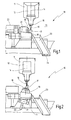
- Fig. 1 10 denotes a machine tool, at whose Travel stand 11 a spindle head is mounted vertically adjustable.
- the spindle head 12 can in this way in a working space 13th be moved in all three spatial directions.
- the spindle head 12 carries a rotatable about a spindle axis 14 driven work spindle 15, in the usual way different Machining tools 16 can be clamped to edit workpiece sections 17, which in a clamping device 18 are clamped.
- the tensioning device 18 is connected to rotary drive 19 to the workpiece sections 17 to rotate about a rotation axis 21, such that the workpiece sections 17 on their four longitudinal sides can be edited. It is also possible to use the workpiece sections 17 with the help of the rotary drive so in rotation put that a turning is possible, in which case in the standing work spindle 15 a turning tool 16 is inserted is. In this way, the machine tool 10 for both Milling as well as for turning workpiece sections 17 can be used.
- the workpiece sections 17 are now of a workpiece bar 22 processed from the rear by the tensioning device 18th is pushed through, so that at its front end at least the workpiece portion 17 projects into the working space 13 and can be edited there.
- the workpiece bar 22 can thereby have any cross-sectional shapes, to which the tensioning device 18 is adjusted accordingly.
- a workpiece portion 17 When a workpiece portion 17 is finished, it becomes by a suitable machining tool 16 or a separately provided chop saw separated from the workpiece bar 22 and removed via a chute 23 from the working space 13.
- a finish machined on the bottom of the slide Workpiece 24 indicated.
- the tensioning device 18 on a in Fig. 2 to Recognized swivel bracket 25 mounted by the axis of rotation 21 can be pivoted so far, until they almost with the Spindle axis 14 is aligned.
- the tensioning device 18 may also the spindle head 12 to be designed to be pivotable, as is now the case in Connection with Fig. 3 will be explained.
- the machine tool 10 of FIG. 3 is also only schematic shown, it again includes the traveling stand 11 and the spindle head 12, which is now about an axis of rotation indicated at 26 can be pivoted in the working space 13 to the Work piece section 17 on its front side 27 to edit can.
- a device 28 is provided, which is in the direction of Rotary axis 21 is displaceable, which is indicated by an arrow 29 becomes.
- the device 28 has a clamping unit 31 into which a Workpiece section 17 or an end piece 37 to be explained can be clamped.
- the workpiece section 17 also on his sixth page 32 for editing accessible by a machining tool 16.
- a schematically indicated tool magazine 33 provided in the various processing tools 34, 35, 36 are stored in the optional Work spindle 15 can be used.
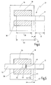
- the end piece 37 is held by two clamping jaws 38, in which it has with its rear section with a minimum span length is held, which is indicated at 39.
- the entire length of the end piece 37 is made up of this minimum span length 39, 41 indicated at the length of the workpiece section 17 and a supernatant 42 together to the the workpiece portion 17 project beyond the clamping jaws 38 must be able to be processed safely in the working space 13.
- the minimum clamping length 39 and the projection 42 determine the Tensioning length 43, by which the end piece 37 is longer than a workpiece portion 17 must be so that the workpiece section 17 still can be edited.
- FIG. 5 a state is shown in a representation like FIG. 4, in which an end piece 37 with the following workpiece bar 22 is connected and only over a residual clamping length 44 in the clamping jaws 38 is held.
- This residual clamping length 44 is chosen so that the tail 37 is still safe between the Clamping jaws 38 is held, so that the workpiece portion 17th can be processed with sufficient accuracy. This is possible because behind the tail 37 between the jaws 38, the next workpiece bar 22 with its front portion 45 sits so that the jaws 38 can not tilt.
- connection 46 Between the end piece 37 and the front portion 45 is a Connection 46 is provided, which are non-positive and by Adhesive, double-sided tape, Velcro or the like can be produced. Only because of this connection 46 is it is possible, the tail 37 so far from the tensioning device 18th push it out, that it only with its residual clamping length 44 is held in the clamping jaws 38.
- the connection 46 prevents Namely, that the end piece 37 when advancing with Help the workpiece bar 22 undefined slips or even falls out of the jig 18.
- connection 46 can be made, for example, by that the workpiece bars 22 before processing start their front sides each with an adhesive layer, a piece Tape or the like are provided. If the next one Workpiece bar 22 then comes into abutment with an end piece 37, stick the two bars together like that.
- the end piece 37 by the of Fig. 3rd known device 28 to remove from the clamping device 18 and advance the workpiece bar 22 so far that they with its front portion 45 of the tensioning device 18th showing.
- the tool 34 used can be, in the present case then a glue gun is.
- the end faces of workpiece bar 22 and end 17 then pressed together and glued together.
- the tail 37 and with him the workpiece rod 22 again so far in the jig 18 pushed in that only the workpiece section 17 sufficiently protrudes beyond the clamping device 18 and can be edited.
- the compound 46 may be used as an adhesive bond as well Spot welded connection can be formed.
- This is the End piece 37 in turn clamped in the device 28, wherein the connection between the workpiece rod 22 and tail 37th now with the help of a in Fig. 3 at 47 indicated welding device takes place, for example, attached to the traveling stand 11 and can be moved by it.
- the welder 47 with its own Provide delivery device, or a corresponding Insert welding tip as a tool in the work spindle 12.
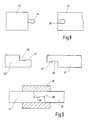
- connection 46th between tail 37 and workpiece bar 22 serves a mold element 48 in the form of a clip thereto, a form-fitting Make connection, which is essentially on train and Pressure is resilient.
- a form-fitting Make connection which is essentially on train and Pressure is resilient.
- the workpiece bars 22 on their respective faces already with corresponding through holes 49 and grooves 51 are provided so that during the Processing the workpiece bars 22 only the mold element 48 must be used. This is done again at the state shown in Fig. 3, where the end piece 37 in the Device 28 is clamped and the workpiece bar 22 via the tensioning device 18 overlooked.
- the front ends become brought into contact with each other and then the mold element 48th used, including a stapler 36 as a kind Machining tool are inserted into the work spindle 12 can.
- the stapler 36th to be provided with its own delivery device.
- FIG. 7 Another example of a positive connection is in Fig. 7, where a snap ring 52 is used to two in the Cross-section each semicircular pin 53 on the tail 37 and the workpiece bar 22 to jam together.
- the tail 37 and the workpiece bar 22nd to connect with each other by means of locking elements, including
- a pin 54 with head may be provided, which in a corresponding recess 55 snaps onto the end piece 37.
- FIG. 9 Another option for a positive connection is shown in Fig. 9, wherein both on the workpiece bar 22 as also at the end piece 37 complementary to each other one Recess 56 and a projection 57 are provided, the on Train are resilient when laterally through the jaws 38th Force is exercised. This workpiece bar 22 and tail 37th when pushing together push each other, can frontally be provided on the projections 37 still chamfers 58.
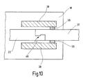
- an additional Holding device 59 is provided, as shown in Fig. 10 is.
- the additional holding device 59 stops when open Jaws 38, the end piece 37 fixed, while from the left the Workpiece rod 22 is advanced, so that it with the tail 37 locks and forms the connection 46 which is shown in FIG Embodiment, the positive connection of FIG. 9 is.
- the Jaws 38 closed so far that a transverse movement of End piece 37 and workpiece bar 22 to each other no longer done can, but still a movement in the longitudinal direction is possible, so the tail 37 is now so far out of the jig 18 can be pushed out until his workpiece section 17th protrudes sufficiently into the working space 13.
Landscapes
- Engineering & Computer Science (AREA)
- Mechanical Engineering (AREA)
- Jigs For Machine Tools (AREA)
Abstract
Description
- Fig. 1
- ein erstes Ausführungsbeispiel einer Werkzeugmaschine, auf der das erfindungsgemäße Verfahren durchgeführt werden kann;
- Fig. 2
- eine Darstellung wie Fig. 1, jedoch mit geschwenkter Spannvorrichtung;
- Fig. 3
- ein weiteres Ausführungsbeispiel einer Werkzeugmaschine, auf der das erfindungsgemäße Verfahren durchgeführt werden kann, in schematischer Seitenansicht;
- Fig. 4
- eine schematische Darstellung der Spannvorrichtung mit eingeklemmter Werkstückstange, wobei Werkstückabschnitt, Spannlänge und Rest-Spannlänge sowie Mindest-Spannlänge erläutert sind;
- Fig. 5
- eine Darstellung wie Fig. 3, jedoch für ein Endstück, das mit der nachfolgenden Werkstückstange verbunden ist;
- Fig. 6
- ein Beispiel für die Verbindung von Endstück und Werkstückstange mit Hilfe eines Formelementes;
- Fig. 7
- eine Darstellung wie Fig. 6, jedoch für ein anderes ausgestaltetes Formelement;
- Fig. 8
- die Verbindung zwischen einem Endstück und einer Werkstückstange durch ein Rastelement;
- Fig. 9
- eine Darstellung wie Fig. 8, jedoch mit einem weiteren Ausführungsbeispiel für die Rastelemente; und
- Fig. 10
- eine schematische Draufsicht auf eine Spannvorrichtung mit einer zusätzlichen Haltevorrichtung, um in der Spannvorrichtung das Endstück und die Werkstückstange miteinander zu verrasten.
Claims (10)
- Verfahren zum Bearbeiten von Werkstückstangen (22) auf einer Werkzeugmaschine (10) mit einer relativ zu einer Spannvorrichtung (18) für die Werkstückstangen (22) verfahrbaren Arbeitsspindel (15), in die Bearbeitungswerkzeuge (16, 34, 35, 36) einspannbar sind, mit den Schritten:dadurch gekennzeichnet, dass im Zusammenhang mit Schritt e) zwischen dem Endstück (37) und der nächsten Werkstückstange (22) eine Verbindung (46) hergestellt wird.a) Einspannen einer Werkstückstange (22) in die Spannvorrichtung (18) derart, dass zumindest ein zu bearbeitender Werkstückabschnitt (17) der Werkstückstange (22) über die Spannvorrichtung (18) übersteht,b) Bearbeiten des Werkstückabschnittes (17) mit zumindest einem Bearbeitungswerkzeug (16),c) Abtrennen des insoweit bearbeiteten Werkstückabschnittes (17) von der restlichen Werkstückstange (22),d) Vorschieben der restlichen Werkstückstange (22), bis zumindest ein neuer Werkstückabschnitt (17) über die Spannvorrichtung (18) übersteht, und erneutes Einspannen der Werkstückstange (22),e) Wiederholen der Schritte b) bis d), bis ein Endstück (37) der in Bearbeitung befindlichen Werkstückstange (22) entsteht, das mit Hilfe der als nächstes zu bearbeitenden Werkstückstange (22) vorgeschoben wird,
- Verfahren nach Anspruch 1, dadurch gekennzeichnet, dass die Verbindung (46) im Wesentlichen auf Zug und Druck belastbar ist.
- Verfahren nach Anspruch 1 oder 2, dadurch gekennzeichnet, dass die Verbindung (46) eine kraftschlüssige Verbindung, vorzugsweise eine Art Klebeverbindung ist.
- Verfahren nach Anspruch 1 oder 2, dadurch gekennzeichnet, dass die Verbindung (46) eine stoffflüssige Verbindung, vorzugsweise eine Punktschweißverbindung ist.
- Verfahren nach Anspruch 1 oder 2, dadurch gekennzeichnet, dass die Verbindung (46) eine formschlüssige Verbindung ist.
- Verfahren nach Anspruch 5, dadurch gekennzeichnet, dass die formschlüssige Verbindung (46) durch ein Formelement (48, 52) hergestellt wird, das mit dem Endstück (37) und der nächsten Werkstückstange (22) in Eingriff gebracht wird.
- Verfahren nach Anspruch 5, dadurch gekennzeichnet, dass die formschlüssige Verbindung (46) durch an dem Endstück (37) und der nächsten Werkstückstange (22) ausgebildete Rastelemente (55, 57; 56, 57) hergestellt wird.
- Verfahren nach Anspruch 7, dadurch gekennzeichnet, dass die Rastelemente (54, 55; 56, 57) im Zusammenhang mit Schritt e) an dem Endstück (37) oder der nächsten Werkstückstange (22) ausgebildet werden.
- Verfahren nach Anspruch 7, dadurch gekennzeichnet, dass die Rastelemente (54, 55; 56, 57) an der Werkstückstange (22) ausgebildet werden, bevor die Bearbeitung der Werkstückabschnitte (17) der Werkstückstange (22) erfolgt.
- Werkzeugmaschine zum Bearbeiten von Werkstückstangen (22), mit einer relativ zu einer Spannvorrichtung (18) für die Werkstückstangen (22) verfahrbaren Arbeitsspindel (15), in die Bearbeitungswerkzeuge (16, 34, 35, 36) einspannbar sind,
dadurch gekennzeichnet, dass sie eine Einrichtung (34, 36, 47, 59) aufweist, die dazu eingerichtet ist, ein Endstück (37) einer in Bearbeitung befindlichen Werkstückstange (22) mit einer als nächstes zu bearbeitenden Werkstückstange (22) zu verbinden.
Priority Applications (1)
| Application Number | Priority Date | Filing Date | Title |
|---|---|---|---|
| PL05012802T PL1607176T3 (pl) | 2004-06-14 | 2005-06-14 | Sposób obróbki półwyrobów prętowych |
Applications Claiming Priority (2)
| Application Number | Priority Date | Filing Date | Title |
|---|---|---|---|
| DE102004029046A DE102004029046B4 (de) | 2004-06-14 | 2004-06-14 | Verfahren und Werkzeugmaschine zum Bearbeiten von Werkstückstangen |
| DE102004029046 | 2004-06-14 |
Publications (2)
| Publication Number | Publication Date |
|---|---|
| EP1607176A1 true EP1607176A1 (de) | 2005-12-21 |
| EP1607176B1 EP1607176B1 (de) | 2008-10-08 |
Family
ID=34937448
Family Applications (1)
| Application Number | Title | Priority Date | Filing Date |
|---|---|---|---|
| EP05012802A Expired - Lifetime EP1607176B1 (de) | 2004-06-14 | 2005-06-14 | Verfahren zum Bearbeiten von Werkstückstangen |
Country Status (4)
| Country | Link |
|---|---|
| EP (1) | EP1607176B1 (de) |
| DE (1) | DE102004029046B4 (de) |
| ES (1) | ES2314518T3 (de) |
| PL (1) | PL1607176T3 (de) |
Cited By (2)
| Publication number | Priority date | Publication date | Assignee | Title |
|---|---|---|---|---|
| EP1834719A1 (de) * | 2006-03-14 | 2007-09-19 | Stama Maschinenfabrik Gmbh | Werkzeugmaschine und Verfahren zur spanabhebenden Bearbeitung von Werkstücken, insbesondere von metallischen Werkstücken |
| ITUB20161232A1 (it) * | 2016-03-02 | 2017-09-02 | Gian Domenico Dimetto | Macchina multifunzione per la lavorazione meccanica di pezzi complessi. |
Families Citing this family (1)
| Publication number | Priority date | Publication date | Assignee | Title |
|---|---|---|---|---|
| CN103878588B (zh) * | 2012-12-19 | 2016-08-03 | 鸿准精密模具(昆山)有限公司 | 金属件加工方法 |
Citations (3)
| Publication number | Priority date | Publication date | Assignee | Title |
|---|---|---|---|---|
| DE1299482B (de) * | 1966-03-02 | 1969-07-17 | Wendler Gmbh Geb | Langdrehautomat |
| DE4228708A1 (de) * | 1992-08-28 | 1994-03-03 | Chiron Werke Gmbh | Werkzeugmaschine |
| WO1998008648A1 (de) * | 1996-08-30 | 1998-03-05 | Stama Maschinenfabrik Gmbh | Bohr- und fräswerk zum verarbeiten von werkstoffstangen |
Family Cites Families (1)
| Publication number | Priority date | Publication date | Assignee | Title |
|---|---|---|---|---|
| DE2834020A1 (de) * | 1978-08-03 | 1980-02-14 | Karlsruhe Augsburg Iweka | Verfahren und vorrichtung zum verarbeiten handelsueblichen stangenmaterials |
-
2004
- 2004-06-14 DE DE102004029046A patent/DE102004029046B4/de not_active Expired - Fee Related
-
2005
- 2005-06-14 ES ES05012802T patent/ES2314518T3/es not_active Expired - Lifetime
- 2005-06-14 EP EP05012802A patent/EP1607176B1/de not_active Expired - Lifetime
- 2005-06-14 PL PL05012802T patent/PL1607176T3/pl unknown
Patent Citations (3)
| Publication number | Priority date | Publication date | Assignee | Title |
|---|---|---|---|---|
| DE1299482B (de) * | 1966-03-02 | 1969-07-17 | Wendler Gmbh Geb | Langdrehautomat |
| DE4228708A1 (de) * | 1992-08-28 | 1994-03-03 | Chiron Werke Gmbh | Werkzeugmaschine |
| WO1998008648A1 (de) * | 1996-08-30 | 1998-03-05 | Stama Maschinenfabrik Gmbh | Bohr- und fräswerk zum verarbeiten von werkstoffstangen |
Cited By (5)
| Publication number | Priority date | Publication date | Assignee | Title |
|---|---|---|---|---|
| EP1834719A1 (de) * | 2006-03-14 | 2007-09-19 | Stama Maschinenfabrik Gmbh | Werkzeugmaschine und Verfahren zur spanabhebenden Bearbeitung von Werkstücken, insbesondere von metallischen Werkstücken |
| US7367929B2 (en) | 2006-03-14 | 2008-05-06 | Stama Maschinenfabrik Gmbh | Machine tool and method for cutting machining of workpieces |
| CN101036969B (zh) * | 2006-03-14 | 2010-11-03 | 斯塔玛机床有限公司 | 用于工件特别是金属工件的切削加工的机床和方法 |
| EP2255907A1 (de) * | 2006-03-14 | 2010-12-01 | STAMA Maschinenfabrik GmbH | Werkzeugmaschine und Verfahren zur spanabhebenden Bearbeitung von Werkstücken, insbesondere von metallischen Werkstücken |
| ITUB20161232A1 (it) * | 2016-03-02 | 2017-09-02 | Gian Domenico Dimetto | Macchina multifunzione per la lavorazione meccanica di pezzi complessi. |
Also Published As
| Publication number | Publication date |
|---|---|
| EP1607176B1 (de) | 2008-10-08 |
| DE102004029046B4 (de) | 2007-08-23 |
| DE102004029046A1 (de) | 2006-01-05 |
| ES2314518T3 (es) | 2009-03-16 |
| PL1607176T3 (pl) | 2009-03-31 |
Similar Documents
| Publication | Publication Date | Title |
|---|---|---|
| DE19635258C1 (de) | Bohr- und Fräswerk zum Verarbeiten von Werkstoffstangen | |
| EP2340147B1 (de) | Bearbeitungsmaschine für sechsseitige bearbeitung | |
| EP1092494B1 (de) | Bohreinrichtung zum Erzeugen von Bohrungen insbesondere in überlappenden Bauteilen und Verfahren hierzu | |
| DE3320940C2 (de) | ||
| DE102009035839A1 (de) | Vorrichtung zum mechanischen Bearbeiten von rohr- oder stangenförmigen Werkstücken | |
| DE2535202A1 (de) | Werkzeugmaschine und verfahren zur bearbeitung von werkstuecken | |
| DE102004027888B4 (de) | Vorschubeinheit für eine Maschine zum Bearbeiten von Werkstücken aus Holz, Kunststoff oder dergleichen sowie Verfahren zum Bearbeiten solcher Werkstücke | |
| DE3209999A1 (de) | Werkzeugkopf und wechseleinrichtung an werkzeugmaschinen | |
| DE3713515A1 (de) | Flexible spanende fertigungszelle bzw. bearbeitungszentrum | |
| EP0204753A1 (de) | Verfahren und vorrichtung zum abtrennen von rohrstücken. | |
| DE2921458A1 (de) | Vorrichtung zum verarbeiten von rundholzabschnitten zu schnittholz | |
| DE102004029046B4 (de) | Verfahren und Werkzeugmaschine zum Bearbeiten von Werkstückstangen | |
| DE3038779C2 (de) | Gewindeschneidemaschine für Rohre | |
| DE2016364B2 (de) | Spiralbohrer | |
| EP2185331B1 (de) | Vorrichtung zur bearbeitung von werkstücken aus holz, kunststoff und dergleichen sowie verfahren zum bearbeiten von solchen werkstücken | |
| EP1332814B1 (de) | Vorrichtung zum Zuführen von Werkstoffstangen zu einer Werkzeugmaschine | |
| DE3514829A1 (de) | Einrichtung zum halten eines werkzeuges an der spindel einer numerisch gesteuerten werkzeugmaschine | |
| DE2632481C3 (de) | Maschine zum Einbringen von Zentrierbohrungen in die Enden von Stangenmaterial | |
| DE102004019936B4 (de) | Drehmaschine, insbesondere Mehrspindeldrehautomat | |
| DE10145674B4 (de) | Werkzeugmaschine zur Bearbeitung eines stangenförmigen Werkstücks | |
| DE1299482B (de) | Langdrehautomat | |
| DE102010007890B4 (de) | Werkzeugmaschine zum Bearbeiten von schlanken Werkstücken | |
| EP0816029B1 (de) | Abbundanlage zur Bearbeitung von stangenförmigen Holzwerkstücken | |
| EP2734327B1 (de) | Innenräummaschine | |
| AT387174B (de) | Schlittenfuehrung |
Legal Events
| Date | Code | Title | Description |
|---|---|---|---|
| PUAI | Public reference made under article 153(3) epc to a published international application that has entered the european phase |
Free format text: ORIGINAL CODE: 0009012 |
|
| AK | Designated contracting states |
Kind code of ref document: A1 Designated state(s): AT BE BG CH CY CZ DE DK EE ES FI FR GB GR HU IE IS IT LI LT LU MC NL PL PT RO SE SI SK TR |
|
| AX | Request for extension of the european patent |
Extension state: AL BA HR LV MK YU |
|
| 17P | Request for examination filed |
Effective date: 20060603 |
|
| AKX | Designation fees paid |
Designated state(s): DE ES IT PL |
|
| 17Q | First examination report despatched |
Effective date: 20061108 |
|
| RBV | Designated contracting states (corrected) |
Designated state(s): DE ES IT |
|
| GRAP | Despatch of communication of intention to grant a patent |
Free format text: ORIGINAL CODE: EPIDOSNIGR1 |
|
| RBV | Designated contracting states (corrected) |
Designated state(s): DE ES IT PL |
|
| RTI1 | Title (correction) |
Free format text: PROCESS FOR PROCESSING BAR STOCK |
|
| GRAS | Grant fee paid |
Free format text: ORIGINAL CODE: EPIDOSNIGR3 |
|
| GRAA | (expected) grant |
Free format text: ORIGINAL CODE: 0009210 |
|
| RBV | Designated contracting states (corrected) |
Designated state(s): ES IT PL |
|
| AK | Designated contracting states |
Kind code of ref document: B1 Designated state(s): ES IT PL |
|
| REG | Reference to a national code |
Ref country code: DE Ref legal event code: 8566 |
|
| REG | Reference to a national code |
Ref country code: ES Ref legal event code: FG2A Ref document number: 2314518 Country of ref document: ES Kind code of ref document: T3 |
|
| REG | Reference to a national code |
Ref country code: PL Ref legal event code: T3 |
|
| PLBE | No opposition filed within time limit |
Free format text: ORIGINAL CODE: 0009261 |
|
| STAA | Information on the status of an ep patent application or granted ep patent |
Free format text: STATUS: NO OPPOSITION FILED WITHIN TIME LIMIT |
|
| PGFP | Annual fee paid to national office [announced via postgrant information from national office to epo] |
Ref country code: PL Payment date: 20090605 Year of fee payment: 5 |
|
| 26N | No opposition filed |
Effective date: 20090709 |
|
| PGFP | Annual fee paid to national office [announced via postgrant information from national office to epo] |
Ref country code: ES Payment date: 20110624 Year of fee payment: 7 |
|
| PGFP | Annual fee paid to national office [announced via postgrant information from national office to epo] |
Ref country code: IT Payment date: 20110622 Year of fee payment: 7 |
|
| REG | Reference to a national code |
Ref country code: PL Ref legal event code: LAPE |
|
| PG25 | Lapsed in a contracting state [announced via postgrant information from national office to epo] |
Ref country code: PL Free format text: LAPSE BECAUSE OF NON-PAYMENT OF DUE FEES Effective date: 20100614 |
|
| PG25 | Lapsed in a contracting state [announced via postgrant information from national office to epo] |
Ref country code: IT Free format text: LAPSE BECAUSE OF NON-PAYMENT OF DUE FEES Effective date: 20120614 |
|
| REG | Reference to a national code |
Ref country code: ES Ref legal event code: FD2A Effective date: 20131021 |
|
| PG25 | Lapsed in a contracting state [announced via postgrant information from national office to epo] |
Ref country code: ES Free format text: LAPSE BECAUSE OF NON-PAYMENT OF DUE FEES Effective date: 20120615 |