EP1607227A2 - Bilderzeugungsgerät und Verfahren - Google Patents
Bilderzeugungsgerät und Verfahren Download PDFInfo
- Publication number
- EP1607227A2 EP1607227A2 EP05250754A EP05250754A EP1607227A2 EP 1607227 A2 EP1607227 A2 EP 1607227A2 EP 05250754 A EP05250754 A EP 05250754A EP 05250754 A EP05250754 A EP 05250754A EP 1607227 A2 EP1607227 A2 EP 1607227A2
- Authority
- EP
- European Patent Office
- Prior art keywords
- image forming
- size
- cutting
- cutting mark
- recording medium
- Prior art date
- Legal status (The legal status is an assumption and is not a legal conclusion. Google has not performed a legal analysis and makes no representation as to the accuracy of the status listed.)
- Withdrawn
Links
- 238000000034 method Methods 0.000 title claims description 17
- 238000007639 printing Methods 0.000 claims abstract description 70
- 238000004590 computer program Methods 0.000 claims 4
- 230000002950 deficient Effects 0.000 abstract description 8
- 238000012545 processing Methods 0.000 description 17
- 238000010586 diagram Methods 0.000 description 9
- 230000008569 process Effects 0.000 description 5
- 230000000694 effects Effects 0.000 description 4
- 238000012937 correction Methods 0.000 description 3
- 238000012546 transfer Methods 0.000 description 3
- 238000004891 communication Methods 0.000 description 2
- 101100172132 Mus musculus Eif3a gene Proteins 0.000 description 1
- 230000015572 biosynthetic process Effects 0.000 description 1
- 230000008859 change Effects 0.000 description 1
- 238000006243 chemical reaction Methods 0.000 description 1
- 230000006835 compression Effects 0.000 description 1
- 238000007906 compression Methods 0.000 description 1
- 238000012790 confirmation Methods 0.000 description 1
- 230000006837 decompression Effects 0.000 description 1
- 238000005516 engineering process Methods 0.000 description 1
- 230000006872 improvement Effects 0.000 description 1
- 239000004973 liquid crystal related substance Substances 0.000 description 1
- 230000009467 reduction Effects 0.000 description 1
- 238000004904 shortening Methods 0.000 description 1
Images


Classifications
-
- B—PERFORMING OPERATIONS; TRANSPORTING
- B41—PRINTING; LINING MACHINES; TYPEWRITERS; STAMPS
- B41J—TYPEWRITERS; SELECTIVE PRINTING MECHANISMS, i.e. MECHANISMS PRINTING OTHERWISE THAN FROM A FORME; CORRECTION OF TYPOGRAPHICAL ERRORS
- B41J11/00—Devices or arrangements of selective printing mechanisms, e.g. ink-jet printers or thermal printers, for supporting or handling copy material in sheet or web form
- B41J11/66—Applications of cutting devices
- B41J11/68—Applications of cutting devices cutting parallel to the direction of paper feed
-
- B—PERFORMING OPERATIONS; TRANSPORTING
- B26—HAND CUTTING TOOLS; CUTTING; SEVERING
- B26D—CUTTING; DETAILS COMMON TO MACHINES FOR PERFORATING, PUNCHING, CUTTING-OUT, STAMPING-OUT OR SEVERING
- B26D5/00—Arrangements for operating and controlling machines or devices for cutting, cutting-out, stamping-out, punching, perforating, or severing by means other than cutting
- B26D5/02—Means for moving the cutting member into its operative position for cutting
-
- B—PERFORMING OPERATIONS; TRANSPORTING
- B26—HAND CUTTING TOOLS; CUTTING; SEVERING
- B26D—CUTTING; DETAILS COMMON TO MACHINES FOR PERFORATING, PUNCHING, CUTTING-OUT, STAMPING-OUT OR SEVERING
- B26D5/00—Arrangements for operating and controlling machines or devices for cutting, cutting-out, stamping-out, punching, perforating, or severing by means other than cutting
- B26D5/20—Arrangements for operating and controlling machines or devices for cutting, cutting-out, stamping-out, punching, perforating, or severing by means other than cutting with interrelated action between the cutting member and work feed
- B26D5/30—Arrangements for operating and controlling machines or devices for cutting, cutting-out, stamping-out, punching, perforating, or severing by means other than cutting with interrelated action between the cutting member and work feed having the cutting member controlled by scanning a record carrier
- B26D5/34—Arrangements for operating and controlling machines or devices for cutting, cutting-out, stamping-out, punching, perforating, or severing by means other than cutting with interrelated action between the cutting member and work feed having the cutting member controlled by scanning a record carrier scanning being effected by a photosensitive device
-
- B—PERFORMING OPERATIONS; TRANSPORTING
- B26—HAND CUTTING TOOLS; CUTTING; SEVERING
- B26D—CUTTING; DETAILS COMMON TO MACHINES FOR PERFORATING, PUNCHING, CUTTING-OUT, STAMPING-OUT OR SEVERING
- B26D7/00—Details of apparatus for cutting, cutting-out, stamping-out, punching, perforating, or severing by means other than cutting
- B26D7/27—Means for performing other operations combined with cutting
-
- B—PERFORMING OPERATIONS; TRANSPORTING
- B41—PRINTING; LINING MACHINES; TYPEWRITERS; STAMPS
- B41J—TYPEWRITERS; SELECTIVE PRINTING MECHANISMS, i.e. MECHANISMS PRINTING OTHERWISE THAN FROM A FORME; CORRECTION OF TYPOGRAPHICAL ERRORS
- B41J11/00—Devices or arrangements of selective printing mechanisms, e.g. ink-jet printers or thermal printers, for supporting or handling copy material in sheet or web form
- B41J11/66—Applications of cutting devices
- B41J11/663—Controlling cutting, cutting resulting in special shapes of the cutting line, e.g. controlling cutting positions, e.g. for cutting in the immediate vicinity of a printed image
-
- B—PERFORMING OPERATIONS; TRANSPORTING
- B41—PRINTING; LINING MACHINES; TYPEWRITERS; STAMPS
- B41J—TYPEWRITERS; SELECTIVE PRINTING MECHANISMS, i.e. MECHANISMS PRINTING OTHERWISE THAN FROM A FORME; CORRECTION OF TYPOGRAPHICAL ERRORS
- B41J11/00—Devices or arrangements of selective printing mechanisms, e.g. ink-jet printers or thermal printers, for supporting or handling copy material in sheet or web form
- B41J11/66—Applications of cutting devices
- B41J11/70—Applications of cutting devices cutting perpendicular to the direction of paper feed
-
- G—PHYSICS
- G03—PHOTOGRAPHY; CINEMATOGRAPHY; ANALOGOUS TECHNIQUES USING WAVES OTHER THAN OPTICAL WAVES; ELECTROGRAPHY; HOLOGRAPHY
- G03G—ELECTROGRAPHY; ELECTROPHOTOGRAPHY; MAGNETOGRAPHY
- G03G15/00—Apparatus for electrographic processes using a charge pattern
- G03G15/65—Apparatus which relate to the handling of copy material
- G03G15/6582—Special processing for irreversibly adding or changing the sheet copy material characteristics or its appearance, e.g. stamping, annotation printing, punching
-
- G—PHYSICS
- G03—PHOTOGRAPHY; CINEMATOGRAPHY; ANALOGOUS TECHNIQUES USING WAVES OTHER THAN OPTICAL WAVES; ELECTROGRAPHY; HOLOGRAPHY
- G03G—ELECTROGRAPHY; ELECTROPHOTOGRAPHY; MAGNETOGRAPHY
- G03G2215/00—Apparatus for electrophotographic processes
- G03G2215/00362—Apparatus for electrophotographic processes relating to the copy medium handling
- G03G2215/00789—Adding properties or qualities to the copy medium
- G03G2215/00814—Cutter
Definitions
- the present invention relates to an image forming apparatus for printing image information where a cutting mark is printed on the recording medium.
- image forming apparatuses may print a cutting mark on a recording medium in addition to image information to be printed.
- the cutting mark identifies a cutting position and makes it easy for the cutting machine to cut the recording medium after printing, thereby improving work efficiency.
- the cutting machine reads the mark for cutting on a recording medium, and cuts the recording medium automatically based on the position of the read cutting mark.
- the cutting machine requires the cutting mark to have a definite form that is peculiar to the cutting machine, and conducts cutting at the position thus read.
- the cutting mark is received by the image forming apparatus from a personal computer or PC, together with the image information, under the condition that the cutting mark is combined in image information.
- One such cutting machine is described for example, in Japanese Non-Examined Patent Publication No. 2002-292831.However, in the aforesaid related art, erroneous cutting is caused when a recording medium is cut by the cutting machine. Namely, erroneous reading is caused when a cutting mark which the cutting machine can read is not compatible with a cutting mark printed on the recording medium.
- the output recording medium may be defective because the cutting position may be different from the targeted position.
- This defective output causes wastefulness of recording media and reduction of printing efficiency.
- Such systems also do not allow an operator to make changes easily, and thus causes improvement of defective output to be time-consuming, because the cutting mark is attached to the image information input to the image forming apparatus.
- the printing area including the image information and the cutting marks will be larger than the original area of the image information.
- the printing area may exceed to the area of recording medium; therefore, there is a possibility that a defective output is produced by the cutting machine because the cutting marks may not be able to be printed on the recording medium.
- an image forming apparatus, method and system that can prevent the cutting machine from generating defective cutting output.
- the invention is one to be achieved to solve the problems in the related art, and its object is to provide an image forming apparatus, method and system that can produce printing outputs that can prevent the cutting machine from generating a defective cutting output.
- an exemplary image forming apparatus consistent with the invention comprises: an inputting device that inputs receives image information; an operation section that selects a cutting mark for reading by a cutting machine; an attaching device that attaches the selected cutting mark to an image of the received image information; and an image forming section that prints on a recording medium the image information and the attached cutting mark; wherein the attaching device attaches the selected cutting mark based on a comparison of a size of the recording medium and a size of the image.
- An exemplary method for forming an image consistent with the invention comprises: receiving image information; selecting a cutting mark for reading by a cutting machine; attaching the selected cutting mark to an image of the received image information; and printing on a recording medium the image information and the attached cutting mark; wherein the attaching operation attaches the selected cutting mark based on a comparison of a size of the recording medium and a size of the image.
- the present invention also includes a recording medium which stores a computer readable program for performing the above method of forming an image.
- Another exemplary method for forming an image consistent with the invention comprises: receiving image information; selecting a cutting mark for reading by a cutting machine; attaching the selected cutting mark to an image of the received image information; and printing on a recording medium the image having the attached cutting mark; wherein the cutting mark is selected such that a size of the image having the selected cutting mark will be less than a size of the recording medium.
- the present invention also includes a recording medium which stores a computer readable program for performing the above method of forming an image.
- the system preferably includes a PC 10, a scanner 20, a printer 30, a LAN 40 and a cutting machine 50.
- the PC 10 is a personal computer which sends image information to the printer 30 through the LAN 40.
- the scanner 20 is an image information reading apparatus which sends image information to the printer 30 through the LAN 40.
- the printer 30 represents an image forming apparatus in which the image information output by the PC 10 or the scanner 20 is printed on a recording medium, such as a transfer sheet or a recording sheet.
- the printer 30 is an electrophotographic printer or an ink jet printer that discharges ink drops.
- the cutting machine 50 cuts the printed recording medium outputted from the printer 30 to a prescribed size.
- the cutting machine 50 may read a position of the cutting mark (which is also referred to herein as a register mark) on the recording medium, and may then cut the recording medium based on this position information.
- the recording medium is cut at cross-shaped register marks printed on four corners of the recording medium.
- a shape of the register mark to be used varies depending on a type of the cutting machine.
- the recording medium outputted from the printer 30 may be subject to batch processing conducted by an operator of the cutting machine 50.
- the LAN 40 is a communication cable through which image information and other data may be transmitted and received among the PC 10, the scanner 20 and the printer 30, by the use, for example, of the CSMA/CD communication protocol.
- Fig. 3 is a functional block diagram showing exemplary functional structure of the printer 30.
- the printer 30 includes image processing section 31, control section 32, image forming section 33 and operation section 34.
- the image processing section 31 includes an operation processor, an image memory and an interface, and it receives image information from the PC 10 or the scanner 20 through the interface. Processing section 31 may then conduct image processing such as ⁇ -correction or bitmap conversion on the image information.
- the operation section 34 has an input device, such as a display portion of an LCD (Liquid Crystal Display), a touch panel or a ten key representing numeric keys.
- the input device may be used for setting various operation parameters for the printing process.
- Section 34 may also set the register mark, which will be explained in greater detail below.
- the control section 32 controls the printer 30 and further includes a central processing unit (or CPU) and a memory. Section 32 may control the printer 30 based on one or more conditions established by the operation section 34. As will be explained in greater detail below, the control section 32 may compose image data of a register mark and the inputted image information by attaching the register mark to the image information.
- the image forming section 33 receives a recording medium from a sheet-feeding tray and prints an image on the recording medium based on printing conditions output by the control section 32. Section 33 may then output the printed recording medium to an output tray.
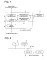
- Fig. 1 is a functional block diagram of an exemplary control section 32 relating to the present embodiment.
- the control section 32 may include an input for receiving image information 60, an input for receiving register mark information 61, an input for receiving size and/or position information 62 regarding the register mark, an attaching section 63 and an image memory 64.
- the image information 60 may be received from the PC 10 or the scanner 20.
- the register mark information 61 preferably includes multiple register mark patterns. Each pattern, for example, may be a version of a base register mark.
- Figs. 4(a) to 4(d) show exemplary register mark patterns that may be stored in the register mark information 61.
- Figs. 4 (a)-4 (d) each illustrate a register mark pattern that may be arranged at the four corners of an image forming a rectangular plane.
- Fig. 4 (a) is an example having two cross-shaped register mark patterns oriented with respect to image information 60.
- the cutting machine may cut the recording medium along cutting lines passing through intersecting points of the crosses formed by the register marks and along the edges of the image information 60.
- Fig. 4 (b) shows an example where two L-shaped register marks are arranged.
- one side of the L-shaped mark is arranged to be along the edge portion of the image.
- the cutting machine may then cut the recording medium along a cutting line passing through the corner portion of the L-shaped register mark and along the edge portion of the image.
- the two register marks show the cutting positions on the cutting directions which substantially cross at right angles at the corner of image information 60.
- Fig. 4 (c) shows an example having an L-shaped register mark pattern and a center-missing L-shaped register mark pattern.
- a corner portion of the image information 60 is located at the center-missing portion of the center-missing L-shaped register mark.
- Cutting may then be conducted so that the cutting line passes through the corner portion of the L-shaped register mark along the edge portion of the image information 60.
- the corner portion of the L-shaped register mark and the corner portion of the cut recording medium coincide with each other.
- Each of the two sides of the L-shaped register mark shown in Fig. 4 (c) correspond to the two cutting directions which substantially cross at right angles at the corner portion of the L-shaped register mark.
- Fig. 4 (d) shows an example having a center-missing L-shaped register mark.
- a corner portion of the image information 60 is located at the center-missing portion of the center-missing L-shaped letter.
- the edge portions of two lines constituting the center-missing L-shaped mark correspond to the cutting position along the edge portion of image information 60.
- the register mark information 61 may have register mark pattern information including cross-shaped, L-shaped, and center-missing L-shaped register marks as illustrated in Figs. 4 (a) - 4 (d).
- the size and/or position information 62 may include information about a size of a register mark and/or of a position of the register mark with respect to the corner portion of the image information.
- Information of a register mark size is shown, for example, by: (1) a distance between a position of an intersection of a cross and a corner portion of the image information 60 in the case of a cross-shaped register mark, (2) a distance between a corner portion of an L-shaped register mark and a corner portion of the image information 60 in the case where one or more L-shaped register marks are arranged and (3) a distance between a center point of two sides constituting a center-missing L letter face each other and a corner portion of the image information 60 in the case of a center-missing L-shaped register mark.
- a register mark may be selected from the register mark information 61, and may be transmitted to the attaching device 63. Further, in the same way, register mark size and/or position information 62 may be generated and transmitted to the attaching device 63 in accordance with instructions from operation section 34.
- the image memory 64 is a memory that stores image information outputted from image forming section 33. Contents of this memory form printing output information which may be printed to agree with the size of a recording medium defined by the operation section 34. Therefore, the size of a printing output range may agree with the size of the memory 64 and the size of the recording medium. When contents of the memory 64 need to be preserved in the control section 32, the contents of the memory 64 may be subject to an image compression, and may then be subject to image decompression for printing.
- Attaching device 63 may attach a register mark on image information 60 based on the image information 60, register mark information 61 and register mark size and/or position information 62. Device 63 may then store the register mark in image memory 64.
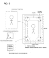
- Fig. 5 is an exemplary diagram showing schematically how the register mark is attached by the attaching device 63.
- the image information 60 is arranged at a prescribed position within the center of the image memory 64 showing a printing output range.
- the register mark may also be associated with a size of the register mark and respective positions from four corners of the image, based on the register mark information 61 instructed by operation section 34 and on the register mark size and/or position information 62.
- the attaching device 63 may then arrange the register marks respectively at four corners existing on the image on the page memory 64 by optimizing a direction, a size and a position of each register mark.
- the attaching device 63 confirms a print range representing a minimum rectangular area surrounding the image information 60 and the register marks to be arranged in the image memory 64.
- the device 63 may then compute a printing range that has a blank region with a prescribed width around the periphery of the print range.
- the attaching device 63 may discontinue writing data to the image memory 64, and transmit a warning signal to operation section 34.
- the operation section 34 may then receive the warning signal and display the warning on the display section.
- the attaching device 63 may have a changing device that may change a width of a blank region based on the register mark size and/or position information 62.
- the changing device may make the blank large, so that cutting may be conducted by cutting machine 50 properly.
- the specific relationship between a size of the register mark and a width of the blank region may be adjusted for the particular application based on routine experimentation.
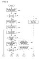
- Fig. 6 and Fig. 7 are flow charts showing exemplary operations of printer 30.
- an operator operates keys of operation section 34 to instruct printing of a register mark (step S601).
- the control section 32 determines whether or not a size of a recording medium inputted from the operation section 34 is greater than or equal to an image size defined by, for example, image property information such as a header of image information 60 (step S602).
- Fig. 8 shows an exemplary displayed image area to be displayed on a display section of the operation section 34.
- a comment showing the state of the control section 32 or actions of a user (e.g., "Image size is too large to print register mark", "Register mark printing is possible", or "Select a type of register mark”).
- On the lower left part there may be provided a "clear” button which instructs removal of the image information 60, and a "register mark printing” button for selecting whether to print the register mark, or a selectable image areas for allowing an operator to select a particular register mark pattern.
- the lower right portion may also display an input for the register mark size and an input for the position information.
- control section 32 may discontinue writing to image memory 64 based on warning signals coming from the attaching device 63, and indicate the impossibility of printing on the display section (step S615) to end the processing.
- the display to the effect that "image size is too large to print register mark" may appear on the comment column on the upper part of the image area, as shown in Fig. 8 (a).
- the register mark printing button at the lower left part of the display section may be made to be in a masked state, which shows that the register mark printing button is unusable.
- the system may display both of the image size and a size of a transfer sheet or recording medium (e.g., that the recording medium is A4 sized paper).
- a size of a recording medium is greater than or equal to the image size ("YES" in step S602)
- the control section 32 indicates "possibility of register mark printing" on the display section of the operation section 34 (step S603).
- Fig. 8 (b) shows an example of the image area of the display section in this case. On the comment column on the upper part of the image area, there appears a display to the effect that "register mark printing is possible.” The register mark printing button on the lower left part is then displayed in a state showing that the register mark printing button is usable. In addition, at the lower right part of the display section, there appears the display to the effect that an image size is A4, and a transfer sheet size is A4W.
- An operator may then select the register mark printing button (step S604), and inputs a register mark pattern showing a shape of a register mark, a size of the selected register mark pattern, and/or a position of the register mark through the operation section 34 (step S605).
- Fig. 8 (c) shows an example of a displayed image area in this case.
- a display for selecting a type of a register mark In the comment column on the upper part of the image area, there is shown a display for selecting a type of a register mark.
- register mark patterns which can be selected, while the lower right part may indicate an input image area showing a line length (representing a size of the register mark) and an image distance (indicating a distance from a corner section of the image to the register mark patterns).
- the line length and an image distance may be inputted by the use of a ten-key pad input terminal, or by any other type of input device known to those of ordinary skill in the art. In this way, a shape and a size of the register mark may be defmed so that they may be read by cutting machine 50.
- attaching device 63 of the control section 32 may determine whether the recording medium size is equal to or greater than a printing range of image information 60 having the attached selected register marks (step S606). In this case (“YES" in step S606), the attaching device 63 may generate the image in image memory 64 (step s607) because all image information can be printed when the recording medium size is equal to or greater than the printing range.
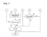
- the control section 32 may then determine, based on key operations conducted by an operator of the operation section 34, whether to confirm the output (step S608). If the output is to be confirmed ("YES” in step S608), the control section 32 confirms the output (step S609 in Fig. 7). In this regard, the operator confirms that the image information (with attached register marks) on the recording medium is as desired for printing (step S610). If so (“YES” in step S610), then the operator may conduct the actual printing (step S611) to end the processing. When the image information is, however, not as desired (“NO” in step S610), the operator may use input key operations of operation section 34 to return the processing to step S605, where a shape and a size of the register mark may be inputted again. These key operations for returning to step S605 may thus serve as a reset device.
- control section 32 moves the processing flow directly to step S611 to print the image and end the processing.
- step S606 when a recording medium size is smaller than a printing range of image information 60 having the attached register marks ("NO" in step S606), the control section 32 displays "impossibility of printing" on a display section (step S612). For example, by using a display image area isuch as that shown in Fig. 8 (a), a display to the effect that the image size with an attached register mark is too large to print the register mark is shown in the comment column on the upper part of the image area.
- the operator may then select whether to require the system to still print the image information 60 having the attached register mark or whether to clear the image information (step S613).
- the processing ends, while, when the clear button is not selected ("NO” in step S614 in Fig. 7), the system will still print the image information and register mark at step S611 to end the processing.
- printer 30 uses attaching device 63 to attach register mark information 61 having a specified shape, size, and position to image information 60 for reading by a cutting machine 50. Further, according to the above exemplary embodiment, when a printing range of the image information 60 with the attached register mark exceeds a printing output range representing a size of image memory 64 or a recording medium size, a warning is given to discontinue printing, which prevents erroneous reading of the register mark by the cutting machine, reduces defective output of a recording medium from the cutting machine and improves printing efficiency.
- the exemplary register marks described above are cross-shaped marks and L-shaped marks, the register marks may also be a point or any peculiar or identifying mark, provided that the register mark may be identified or read by cutting machine 50.
- the attaching device 63 may also be present on the image processing section 31 or on the image forming section 33.
- Fig. 9 is a flow chart illustrating another exemplary embodiment for forming an image consistent with the invention.
- the flow chart of Fig. 9 is similar to the flow charts of Figs. 6 and 7, where like or similar processing steps have been labeled with the same reference numerals.
- processing steps S601 to S604 operate the same as described above with respect to Fig. 6.
- after the operator may select a register mark printing button (S604), and inputs a register pattern that represents a shape of the register mark (S905-a), and at least one of a size (S905-b) and a position (S905-c or S905-d) of the register mark.
- the other parameter may then be treated using an "auto" mode, such that the parameter is automatically calculated by reference to the image size, recording medium size, and the inputted information (steps S905-e or S905-f).
- the system may prompt the operator to select between re-inputting the register mark size or designating the register mark position.
- the system will generate the image in image memory 64 (step S607) and then print the image (step S611) to end the process.
- the attaching device 63 of the control section 32 may determine whether the recording medium size is equal to or greater than a printing range of image information 60 having the attached selected register marks (step S606).
- step S907 the system may display selection keys of "auto layout,” "correction of input,” “forced output,” and/or “clear” to the operator (step S907).
- the system will then conduct an appropriate processes, such as those described above with respect to Figs. 6 to 8, based on the selection by the operator. For instance, when "auto layout” is selected (step S908), priority is given to the register mark positions.
- the auto layout process may automatically attempt to fit the whole image area into the recording medium size by, for example, scaling down the register mark, or shortening the length of the line that over-protrudes with respect to each cross-point of cross shaped or L shaped register marks.
- the register mark positions may also be modified.
- the process may return, for example, to step S604 of Fig. 6 and proceed according to the processing of Fig. 6.
- step S909 the print output may be carried out with cutting top and bottom portions or right and left portions of the resultant image in order that the inputted image information is laid out at the center position of the recording medium (step s910). If "clear" is selected (step S911), the target image formation job may be cancelled.
Landscapes
- Life Sciences & Earth Sciences (AREA)
- Forests & Forestry (AREA)
- Engineering & Computer Science (AREA)
- Mechanical Engineering (AREA)
- Physics & Mathematics (AREA)
- General Physics & Mathematics (AREA)
- Handling Of Sheets (AREA)
Applications Claiming Priority (2)
| Application Number | Priority Date | Filing Date | Title |
|---|---|---|---|
| JP2004179154 | 2004-06-17 | ||
| JP2004179154 | 2004-06-17 |
Publications (2)
| Publication Number | Publication Date |
|---|---|
| EP1607227A2 true EP1607227A2 (de) | 2005-12-21 |
| EP1607227A3 EP1607227A3 (de) | 2008-09-17 |
Family
ID=35124506
Family Applications (1)
| Application Number | Title | Priority Date | Filing Date |
|---|---|---|---|
| EP05250754A Withdrawn EP1607227A3 (de) | 2004-06-17 | 2005-02-09 | Bilderzeugungsgerät und Verfahren |
Country Status (2)
| Country | Link |
|---|---|
| US (1) | US20050281184A1 (de) |
| EP (1) | EP1607227A3 (de) |
Cited By (2)
| Publication number | Priority date | Publication date | Assignee | Title |
|---|---|---|---|---|
| CN103260835A (zh) * | 2010-10-08 | 2013-08-21 | 株式会社御牧工程 | 切割程序、切割系统以及切割方法 |
| WO2015181145A1 (en) * | 2014-05-27 | 2015-12-03 | Oce-Technologies B.V. | Document reproduction and finishing system and method |
Families Citing this family (7)
| Publication number | Priority date | Publication date | Assignee | Title |
|---|---|---|---|---|
| JP5168124B2 (ja) * | 2008-12-18 | 2013-03-21 | 富士通株式会社 | 画像のマーカ付加装置、方法、及びプログラム |
| JP2013144343A (ja) * | 2012-01-16 | 2013-07-25 | Brother Industries Ltd | 切断装置 |
| JP6567398B2 (ja) * | 2015-11-27 | 2019-08-28 | コニカミノルタ株式会社 | 画像形成システム |
| JP6724411B2 (ja) * | 2016-02-24 | 2020-07-15 | 株式会社リコー | 情報処理システム、情報処理装置およびプログラム |
| ITUA20163797A1 (it) * | 2016-05-25 | 2017-11-25 | Fotoba Int S R L | Metodo e dispositivo automatico per il taglio di substrati recanti immagini stampate |
| JP2018126891A (ja) * | 2017-02-07 | 2018-08-16 | コニカミノルタ株式会社 | 画像処理装置、画像形成装置、画像処理装置の制御プログラム、および画像形成装置の制御プログラム |
| JP7332345B2 (ja) * | 2019-05-29 | 2023-08-23 | キヤノン株式会社 | プログラム、制御方法及び画像処理装置 |
Family Cites Families (4)
| Publication number | Priority date | Publication date | Assignee | Title |
|---|---|---|---|---|
| US5271065A (en) * | 1990-09-28 | 1993-12-14 | Xerox Corporation | Electronic printing system for printing signatures |
| JP3008541B2 (ja) * | 1991-04-16 | 2000-02-14 | ブラザー工業株式会社 | プリント方法 |
| US5631747A (en) * | 1995-08-21 | 1997-05-20 | Xerox Corporation | Apparatus and method for applying trim marks to a print media sheet |
| US6112658A (en) * | 1999-02-25 | 2000-09-05 | George Schmitt & Company, Inc. | Integrated and computer controlled printing press, inspection rewinder and die cutter system |
-
2005
- 2005-02-07 US US11/050,751 patent/US20050281184A1/en not_active Abandoned
- 2005-02-09 EP EP05250754A patent/EP1607227A3/de not_active Withdrawn
Cited By (2)
| Publication number | Priority date | Publication date | Assignee | Title |
|---|---|---|---|---|
| CN103260835A (zh) * | 2010-10-08 | 2013-08-21 | 株式会社御牧工程 | 切割程序、切割系统以及切割方法 |
| WO2015181145A1 (en) * | 2014-05-27 | 2015-12-03 | Oce-Technologies B.V. | Document reproduction and finishing system and method |
Also Published As
| Publication number | Publication date |
|---|---|
| EP1607227A3 (de) | 2008-09-17 |
| US20050281184A1 (en) | 2005-12-22 |
Similar Documents
| Publication | Publication Date | Title |
|---|---|---|
| US9992374B2 (en) | Image processing apparatus and image processing method | |
| JP4791710B2 (ja) | 印刷装置、プログラム、印刷システムおよび印刷制御方法 | |
| EP1607227A2 (de) | Bilderzeugungsgerät und Verfahren | |
| CN114193948A (zh) | 印刷装置、印刷物生产方法以及记录有程序的记录介质 | |
| KR101310236B1 (ko) | 호스트 장치의 축소인쇄 제어 방법 및 그를 위한 호스트장치 | |
| EP1973331B1 (de) | Druckvorrichtung, Druckverfahren und Computerprogramm dafür | |
| JP2006027259A (ja) | 画像形成装置、画像形成方法、及び画像形成システム | |
| US7292366B2 (en) | Printing control system, printing control method and program | |
| US8564824B2 (en) | System and printing method to generate printing data of an image to be printed over a plurality of recording pages | |
| JP6206296B2 (ja) | 画像データ処理装置、画像データ処理方法及び画像データ処理プログラム | |
| JP6197487B2 (ja) | 印刷装置 | |
| JP4665806B2 (ja) | 印刷装置、印刷方法、および印刷プログラム | |
| CN101154149B (zh) | 打印系统及打印设备 | |
| JP4712561B2 (ja) | 画像形成装置および画像形成方法 | |
| JP2007295222A (ja) | 連続印刷用画像処理システムおよび連続印刷用画像処理プログラム、並びに連続印刷用画像処理方法 | |
| EP3543024B1 (de) | Drucksystem und verfahren zur steuerung des drucksystems | |
| JP2011242936A (ja) | 検版支援方法、その装置及びそのプログラム | |
| JP4904987B2 (ja) | 印刷方法、印刷装置および印刷プログラム | |
| JP2009214394A (ja) | 画像形成装置、及び印刷制御システム | |
| JP2007293658A (ja) | 連続印刷用画像処理システムおよび連続印刷用画像処理プログラム、並びに連続印刷用画像処理方法 | |
| US11656820B2 (en) | Print instruction apparatus, storage medium, and print system | |
| JP2020197969A (ja) | データ処理装置、及びデータ処理プログラム | |
| JP2005142614A (ja) | スキャナドライバプログラム、情報処理装置、及びコピーシステム | |
| US20250004682A1 (en) | Recording system, data generating method, and medium | |
| JP3070381B2 (ja) | 見当マーク焼付位置演算方法 |
Legal Events
| Date | Code | Title | Description |
|---|---|---|---|
| PUAI | Public reference made under article 153(3) epc to a published international application that has entered the european phase |
Free format text: ORIGINAL CODE: 0009012 |
|
| AK | Designated contracting states |
Kind code of ref document: A2 Designated state(s): AT BE BG CH CY CZ DE DK EE ES FI FR GB GR HU IE IS IT LI LT LU MC NL PL PT RO SE SI SK TR |
|
| AX | Request for extension of the european patent |
Extension state: AL BA HR LV MK YU |
|
| PUAL | Search report despatched |
Free format text: ORIGINAL CODE: 0009013 |
|
| AK | Designated contracting states |
Kind code of ref document: A3 Designated state(s): AT BE BG CH CY CZ DE DK EE ES FI FR GB GR HU IE IS IT LI LT LU MC NL PL PT RO SE SI SK TR |
|
| AX | Request for extension of the european patent |
Extension state: AL BA HR LV MK YU |
|
| RIC1 | Information provided on ipc code assigned before grant |
Ipc: B26D 5/32 20060101ALI20080809BHEP Ipc: H04N 1/387 20060101ALI20080809BHEP Ipc: G03G 15/00 20060101ALI20080809BHEP Ipc: B41J 11/66 20060101AFI20051028BHEP |
|
| 17P | Request for examination filed |
Effective date: 20090316 |
|
| AKX | Designation fees paid |
Designated state(s): DE FR GB |
|
| 17Q | First examination report despatched |
Effective date: 20090427 |
|
| STAA | Information on the status of an ep patent application or granted ep patent |
Free format text: STATUS: THE APPLICATION IS DEEMED TO BE WITHDRAWN |
|
| 18D | Application deemed to be withdrawn |
Effective date: 20090908 |