EP1607290A1 - Corps cylindrique - Google Patents
Corps cylindrique Download PDFInfo
- Publication number
- EP1607290A1 EP1607290A1 EP20050105202 EP05105202A EP1607290A1 EP 1607290 A1 EP1607290 A1 EP 1607290A1 EP 20050105202 EP20050105202 EP 20050105202 EP 05105202 A EP05105202 A EP 05105202A EP 1607290 A1 EP1607290 A1 EP 1607290A1
- Authority
- EP
- European Patent Office
- Prior art keywords
- cylindrical body
- convexities
- narrow portions
- axial direction
- body according
- Prior art date
- Legal status (The legal status is an assumption and is not a legal conclusion. Google has not performed a legal analysis and makes no representation as to the accuracy of the status listed.)
- Granted
Links
Images



Classifications
-
- B—PERFORMING OPERATIONS; TRANSPORTING
- B60—VEHICLES IN GENERAL
- B60R—VEHICLES, VEHICLE FITTINGS, OR VEHICLE PARTS, NOT OTHERWISE PROVIDED FOR
- B60R25/00—Fittings or systems for preventing or indicating unauthorised use or theft of vehicles
- B60R25/01—Fittings or systems for preventing or indicating unauthorised use or theft of vehicles operating on vehicle systems or fittings, e.g. on doors, seats or windscreens
- B60R25/02—Fittings or systems for preventing or indicating unauthorised use or theft of vehicles operating on vehicle systems or fittings, e.g. on doors, seats or windscreens operating on the steering mechanism
- B60R25/021—Fittings or systems for preventing or indicating unauthorised use or theft of vehicles operating on vehicle systems or fittings, e.g. on doors, seats or windscreens operating on the steering mechanism restraining movement of the steering column or steering wheel hub, e.g. restraining means controlled by ignition switch
- B60R25/02105—Arrangement of the steering column thereof
- B60R25/02107—Arrangement of the steering column thereof comprising overload clutching means
-
- F—MECHANICAL ENGINEERING; LIGHTING; HEATING; WEAPONS; BLASTING
- F16—ENGINEERING ELEMENTS AND UNITS; GENERAL MEASURES FOR PRODUCING AND MAINTAINING EFFECTIVE FUNCTIONING OF MACHINES OR INSTALLATIONS; THERMAL INSULATION IN GENERAL
- F16D—COUPLINGS FOR TRANSMITTING ROTATION; CLUTCHES; BRAKES
- F16D7/00—Slip couplings, e.g. slipping on overload, for absorbing shock
- F16D7/02—Slip couplings, e.g. slipping on overload, for absorbing shock of the friction type
- F16D7/021—Slip couplings, e.g. slipping on overload, for absorbing shock of the friction type with radially applied torque-limiting friction surfaces
-
- F—MECHANICAL ENGINEERING; LIGHTING; HEATING; WEAPONS; BLASTING
- F16—ENGINEERING ELEMENTS AND UNITS; GENERAL MEASURES FOR PRODUCING AND MAINTAINING EFFECTIVE FUNCTIONING OF MACHINES OR INSTALLATIONS; THERMAL INSULATION IN GENERAL
- F16D—COUPLINGS FOR TRANSMITTING ROTATION; CLUTCHES; BRAKES
- F16D1/00—Couplings for rigidly connecting two coaxial shafts or other movable machine elements
- F16D1/06—Couplings for rigidly connecting two coaxial shafts or other movable machine elements for attachment of a member on a shaft or on a shaft-end
- F16D1/08—Couplings for rigidly connecting two coaxial shafts or other movable machine elements for attachment of a member on a shaft or on a shaft-end with clamping hub; with hub and longitudinal key
- F16D1/0829—Couplings for rigidly connecting two coaxial shafts or other movable machine elements for attachment of a member on a shaft or on a shaft-end with clamping hub; with hub and longitudinal key with radial loading of both hub and shaft by an intermediate ring or sleeve
- F16D1/0835—Couplings for rigidly connecting two coaxial shafts or other movable machine elements for attachment of a member on a shaft or on a shaft-end with clamping hub; with hub and longitudinal key with radial loading of both hub and shaft by an intermediate ring or sleeve due to the elasticity of the ring or sleeve
Definitions
- the present invention relates to a cylindrical body for generating slip torque between two members.
- a cylindrical body (slip ring) for generating slip torque is used in a shock absorbing mechanism for a steering shaft (for example, Japanese Patent No. 3174266), a disc drive storage device (for example, Japanese Published Patent Publication No. 2003-518592) or the like.
- the slip ring includes a slit provided in an axial direction and convexities provided in parallel with the axial direction at plural circumferential positions.
- the slip ring configured as described above is placed between two members which are engaged with each other so as to allow their relative rotation, and the inner circumferential surface of the slip ring contacts with the outer peripheral surface of one of the members.
- the top surfaces of the convexities contact with the inner circumferential surface of the other member, and these convexities are pressed to cause plastic deformation thereof.
- the reaction force of the convexities caused by pressing the convexities generates slip torque.
- the reaction force of the convexities caused by pressing the convexities is generated at the both longitudinal ends of the top surfaces thereof.
- the slip ring configured as in Japanese Patent No. 3174266 and Japanese Published Patent Publication No. 2003-518592 includes convexities having top surfaces with substantially a constant width between the both ends, and a single convexity generates reaction force only at two positions when being pressed.
- the present invention has been made with the aim of solving the above problem, and it is an object of the present invention to provide a cylindrical body which is capable of generating relatively large slip torque and enables reducing the size thereof.
- a cylindrical body according to a first aspect of the present invention is a cylindrical body disposed between two members which are engaged with each other so as to allow their relative rotation, and comprises a slit provided in an axial direction and convexities provided in parallel with the axial direction at plural circumferential positions, characterized in that the convexities have narrow portions.
- a cylindrical body is disposed between two members which are engaged with each other so as to allow their relative rotation, and the inner circumferential surface of the cylindrical body contacts with the outer peripheral surface of one of the members, and the top surfaces of the convexities of the cylindrical body contact with the inner circumferential surface of the other member. Consequently, these convexities are pressed to cause plastic deformation thereof.
- the reactive force of the convexities caused by pressing the convexities generates slip torque.
- the convexities are provided with narrow portions and a single convexity generates, by being pressed, reactive force, at the both longitudinal ends and at the narrow portions, thereby generating relatively large slip torque.
- the axial length of the cylindrical body can be made relatively small, thus enabling reduction of the size thereof.
- the cylindrical body according to a second aspect of the present invention is characterized in that, in the first aspect, the convexities include recessed portions provided at parts of the both side surfaces thereof, as the narrow portions.
- the second aspect it is possible to generate large reactive force at the narrow portions by pressing, in comparison with a cylindrical body including recessed portions provided at one side surfaces of the convexities, thus enabling further reduction of the size of the cylindrical body.
- relatively large slip torque can be generated, and the axial length of the cylindrical body can be made relatively small, thereby enabling reduction of the size of the entire cylindrical body.
- the reactive force at the narrow portions by pressing can be further increased, and the size of the entire cylindrical body can be further reduced.
- FIG. 1 is a perspective view illustrating the configuration of a cylindrical body according to the present invention.
- FIG. 2 is an enlarged perspective view illustrating the configuration of main parts of the cylindrical body.
- FIG. 3 is a cross sectional view along line III-III in FIG. 2.
- FIG. 4 is a cross sectional view along line IV-IV in FIG. 2.
- FIG. 5 is a cross sectional view along line V-V in FIG. 2.
- a cylindrical body A includes a slit 1 provided in an axial direction, and convexities 2 provided at plural circumferential positions in parallel with the axial direction.
- the cylindrical body A is formed by bending, into substantially a cylindrical shape, a relatively-thin metal plate, such as a spring steel plate, which has the plural convexities 2 formed in parallel with one another, and the slit 1 is provided therein at a single circumferential position. Further, the convexities 2 are provided from the vicinity of one axial end to the vicinity of the other axial end.
- the convexities 2 include top surfaces 2a and circumferential surfaces 2b (side surfaces) continuous with the circumferential edge of the top surface 2a, and the convexities 2 are provided with narrow portions 21 having a width dimension smaller than the width dimension of the convexities 2, at plural positions between both the longitudinal ends of the convexities 2. Further, the narrow portions 21 are constituted by recessed portions provided at parts of the both side surfaces of the convexities 2. The circumferential surfaces of the narrow portions 21 and the non-narrow portions 22 are curved in substantially a waveform.
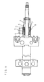
- FIG. 6 is a partially sectional plan view illustrating the configuration of a steering apparatus utilizing the cylindrical body
- FIG. 7 is an enlarged cross sectional view of the key lock unit.
- the steering apparatus B includes a steering shaft 3 which is coupled at its upper portion to a steering wheel for steering and also is coupled and engaged at its lower portion with a steering mechanism through transmitting means such as a universal joint, a housing 4 which houses and supports the steering shaft 3 rotatably, and a vehicle anti-theft key lock unit C mounted to the housing 4 and the steering shaft 3.
- the key lock unit C includes a cylinder 5 mounted to the upper side of the housing 4, a lock pin 6 which is rotatably held within the cylinder 5 and is moved in the radial direction of the housing 4 in conjunction with the rotation of a rotation operating member (not shown) including a key hole for an engine key, a locking cylinder 7 which is loosely fitted around the steering shaft 3 and has a locking hole 7a for locking the end of the lock pin 6, and the cylindrical body A disposed between the locking cylinder 7 and the steering shaft 3, wherein the cylindrical body A secures the locking cylinder 7 around the steering shaft 3 and thus the cylindrical body A generates slip torque.
- the cylindrical body A disposed between the locking cylinder 7 and the steering shaft 3 contacts at its inner circumferential surface with the outer peripheral surface of the steering shaft 3.
- the top surfaces 2a of the convexities 2 contact with the inner circumferential surface of the locking cylinder 7, and the convexities 2 are pressed to cause plastic deformation thereof.
- the reaction force of the convexities 2 caused by pressing the convexities 2 generates slip torque.
- These convexities 2 are provided with narrow portions 21 at plural positions between both the longitudinal ends, and a single convexity 2 generates reactive force at both the longitudinal ends and the plural narrow portions 21. Consequently, relatively large slip torque can be generated and furthermore the axial length of the cylindrical body A can be made relatively small, thus enabling reduction of the size thereof.
- the cylindrical body A according to the present invention may also be disposed between two members which are engaged with each other so as to allow their relative rotation such as in the shock-absorbing mechanism of the steering apparatus B and disk devices, in addition to the key lock unit C of the steering apparatus B.
- the area of utilization thereof is not particularly limited.
Landscapes
- Engineering & Computer Science (AREA)
- General Engineering & Computer Science (AREA)
- Mechanical Engineering (AREA)
- Lock And Its Accessories (AREA)
- Mutual Connection Of Rods And Tubes (AREA)
- Springs (AREA)
- Vibration Dampers (AREA)
Applications Claiming Priority (2)
| Application Number | Priority Date | Filing Date | Title |
|---|---|---|---|
| JP2004175747 | 2004-06-14 | ||
| JP2004175747A JP2005351457A (ja) | 2004-06-14 | 2004-06-14 | 筒体 |
Publications (2)
| Publication Number | Publication Date |
|---|---|
| EP1607290A1 true EP1607290A1 (fr) | 2005-12-21 |
| EP1607290B1 EP1607290B1 (fr) | 2008-10-29 |
Family
ID=34940161
Family Applications (1)
| Application Number | Title | Priority Date | Filing Date |
|---|---|---|---|
| EP20050105202 Expired - Lifetime EP1607290B1 (fr) | 2004-06-14 | 2005-06-14 | Corps cylindrique |
Country Status (3)
| Country | Link |
|---|---|
| EP (1) | EP1607290B1 (fr) |
| JP (1) | JP2005351457A (fr) |
| DE (1) | DE602005010632D1 (fr) |
Cited By (6)
| Publication number | Priority date | Publication date | Assignee | Title |
|---|---|---|---|---|
| DE102006036858A1 (de) * | 2006-08-07 | 2008-06-05 | GM Global Technology Operations, Inc., Detroit | Lenkspindelverriegelung für Fahrzeug |
| FR2929214A1 (fr) * | 2008-03-25 | 2009-10-02 | Renault Sas | Dispositif antivol pour arbre de direction de vehicule automobile |
| EP2054886A4 (fr) * | 2006-08-15 | 2009-12-30 | Intriplex Technologies Inc | Anneau de tolérance présentant une hauteur variable et/ou des bosses disposées de façon asymétrique |
| DE102008040877A1 (de) * | 2008-07-31 | 2010-02-04 | Zf Lenksysteme Gmbh | Vorrichtung zum Verriegeln einer Lenkung und damit ausgestattetes Lenksystem |
| CN104812634A (zh) * | 2012-11-26 | 2015-07-29 | 日本精工株式会社 | 转向装置 |
| US9102292B2 (en) | 2012-11-26 | 2015-08-11 | Nsk Ltd. | Steering apparatus |
Families Citing this family (2)
| Publication number | Priority date | Publication date | Assignee | Title |
|---|---|---|---|---|
| JP6075541B2 (ja) * | 2013-02-18 | 2017-02-08 | アイシン精機株式会社 | 車両のステアリング装置 |
| JP6847554B2 (ja) * | 2018-08-27 | 2021-03-24 | 卓也 澤田 | ホルダー部材 |
Citations (8)
| Publication number | Priority date | Publication date | Assignee | Title |
|---|---|---|---|---|
| DE1855948U (de) * | 1959-12-14 | 1962-08-02 | Martin Hausner | Verdrehsicheres verbindungselement zur befestigung von maschinenteilen auf wellen. |
| FR1337146A (fr) * | 1961-11-02 | 1963-09-06 | Angus George Co Ltd | Bague de tolérance |
| US3838928A (en) * | 1972-03-06 | 1974-10-01 | Star Kugelhalter Gmbh Dt | Spacer ring |
| DE2361218A1 (de) * | 1973-12-08 | 1975-06-12 | Schaeffler Ohg Industriewerk | Toleranzring aus blech |
| DE3435084A1 (de) * | 1984-09-25 | 1986-04-03 | Daimler-Benz Ag, 7000 Stuttgart | Lenkschloss fuer kraftfahrzeuge |
| EP0373239A1 (fr) * | 1987-10-05 | 1990-06-20 | The Ray Engineering Company, Limited | Anneau ondulé et feuille d'entretoise |
| JPH03174266A (ja) | 1989-12-01 | 1991-07-29 | Nishikawa Kasei Kk | 被塗装体の保持装置 |
| WO1994029609A1 (fr) | 1993-06-16 | 1994-12-22 | Lilleshall Plastics And Engineering Ltd. | Manchons deformables |
Family Cites Families (1)
| Publication number | Priority date | Publication date | Assignee | Title |
|---|---|---|---|---|
| DE2018367B1 (de) * | 1970-04-16 | 1971-07-29 | Deutsche Star Kugelhalter Gmbh, 8720 Schweinfurt | Verbindungselement fur eine Kupplung mit Klemmbuchse zum Befestigen einer Nabe auf einer Welle |
-
2004
- 2004-06-14 JP JP2004175747A patent/JP2005351457A/ja active Pending
-
2005
- 2005-06-14 EP EP20050105202 patent/EP1607290B1/fr not_active Expired - Lifetime
- 2005-06-14 DE DE200560010632 patent/DE602005010632D1/de not_active Expired - Lifetime
Patent Citations (8)
| Publication number | Priority date | Publication date | Assignee | Title |
|---|---|---|---|---|
| DE1855948U (de) * | 1959-12-14 | 1962-08-02 | Martin Hausner | Verdrehsicheres verbindungselement zur befestigung von maschinenteilen auf wellen. |
| FR1337146A (fr) * | 1961-11-02 | 1963-09-06 | Angus George Co Ltd | Bague de tolérance |
| US3838928A (en) * | 1972-03-06 | 1974-10-01 | Star Kugelhalter Gmbh Dt | Spacer ring |
| DE2361218A1 (de) * | 1973-12-08 | 1975-06-12 | Schaeffler Ohg Industriewerk | Toleranzring aus blech |
| DE3435084A1 (de) * | 1984-09-25 | 1986-04-03 | Daimler-Benz Ag, 7000 Stuttgart | Lenkschloss fuer kraftfahrzeuge |
| EP0373239A1 (fr) * | 1987-10-05 | 1990-06-20 | The Ray Engineering Company, Limited | Anneau ondulé et feuille d'entretoise |
| JPH03174266A (ja) | 1989-12-01 | 1991-07-29 | Nishikawa Kasei Kk | 被塗装体の保持装置 |
| WO1994029609A1 (fr) | 1993-06-16 | 1994-12-22 | Lilleshall Plastics And Engineering Ltd. | Manchons deformables |
Cited By (8)
| Publication number | Priority date | Publication date | Assignee | Title |
|---|---|---|---|---|
| DE102006036858A1 (de) * | 2006-08-07 | 2008-06-05 | GM Global Technology Operations, Inc., Detroit | Lenkspindelverriegelung für Fahrzeug |
| EP2054886A4 (fr) * | 2006-08-15 | 2009-12-30 | Intriplex Technologies Inc | Anneau de tolérance présentant une hauteur variable et/ou des bosses disposées de façon asymétrique |
| FR2929214A1 (fr) * | 2008-03-25 | 2009-10-02 | Renault Sas | Dispositif antivol pour arbre de direction de vehicule automobile |
| WO2009122111A3 (fr) * | 2008-03-25 | 2009-12-03 | Renault S.A.S | Dispositif antivol pour arbre de direction de vehicule automobile |
| DE102008040877A1 (de) * | 2008-07-31 | 2010-02-04 | Zf Lenksysteme Gmbh | Vorrichtung zum Verriegeln einer Lenkung und damit ausgestattetes Lenksystem |
| CN104812634A (zh) * | 2012-11-26 | 2015-07-29 | 日本精工株式会社 | 转向装置 |
| US9102292B2 (en) | 2012-11-26 | 2015-08-11 | Nsk Ltd. | Steering apparatus |
| US9266502B2 (en) | 2012-11-26 | 2016-02-23 | Nsk Ltd. | Steering apparatus |
Also Published As
| Publication number | Publication date |
|---|---|
| JP2005351457A (ja) | 2005-12-22 |
| DE602005010632D1 (de) | 2008-12-11 |
| EP1607290B1 (fr) | 2008-10-29 |
Similar Documents
| Publication | Publication Date | Title |
|---|---|---|
| CN100419296C (zh) | 动力传递装置 | |
| US8235184B2 (en) | Disc brake device | |
| US11518359B2 (en) | Brake apparatus for vehicle | |
| JP6516756B2 (ja) | 動力伝達装置 | |
| EP3192719B1 (fr) | Dispositif de servodirection à entraînement électrique | |
| US7455574B2 (en) | Locking system for a spindle of a power tool | |
| US20040112690A1 (en) | Electric disc brake | |
| JP2004332921A (ja) | ウォームギヤ機構及びウォームギヤ機構を搭載した電動パワーステアリング装置 | |
| US20090020377A1 (en) | Disk brake for vehicle | |
| EP1607290B1 (fr) | Corps cylindrique | |
| JP4009429B2 (ja) | 逆入力防止クラッチ | |
| EP1655502B1 (fr) | Appareil de transmission de puissance | |
| JP2005351457A5 (fr) | ||
| EP3954921B1 (fr) | Dispositif de frein à disque | |
| EP3306127B1 (fr) | Arbre de transmission de rotation télescopique et son procédé de production | |
| EP0860344A2 (fr) | Mécanisme de pivotement pour un volant | |
| JP4717848B2 (ja) | ディスクブレーキ用摩擦材組立体、及びその組立方法 | |
| JP2008075867A (ja) | 一方向クラッチユニット | |
| EP3014967B1 (fr) | Sarcleur a pousser | |
| JP2015223660A (ja) | マーキングトルクレンチ | |
| KR20140135328A (ko) | 자동차 조향축의 잠금장치 | |
| JP7845930B2 (ja) | クラッチ装置 | |
| JPH09109903A (ja) | ステアリング機構 | |
| JP2021006357A (ja) | 回転工具用ソケット | |
| JP2005162053A (ja) | ステアリングロック機構 |
Legal Events
| Date | Code | Title | Description |
|---|---|---|---|
| PUAI | Public reference made under article 153(3) epc to a published international application that has entered the european phase |
Free format text: ORIGINAL CODE: 0009012 |
|
| AK | Designated contracting states |
Kind code of ref document: A1 Designated state(s): AT BE BG CH CY CZ DE DK EE ES FI FR GB GR HU IE IS IT LI LT LU MC NL PL PT RO SE SI SK TR |
|
| AX | Request for extension of the european patent |
Extension state: AL BA HR LV MK YU |
|
| RAP1 | Party data changed (applicant data changed or rights of an application transferred) |
Owner name: JTEKT CORPORATION |
|
| 17P | Request for examination filed |
Effective date: 20060620 |
|
| AKX | Designation fees paid |
Designated state(s): DE FR GB |
|
| 17Q | First examination report despatched |
Effective date: 20060811 |
|
| GRAP | Despatch of communication of intention to grant a patent |
Free format text: ORIGINAL CODE: EPIDOSNIGR1 |
|
| GRAS | Grant fee paid |
Free format text: ORIGINAL CODE: EPIDOSNIGR3 |
|
| GRAA | (expected) grant |
Free format text: ORIGINAL CODE: 0009210 |
|
| AK | Designated contracting states |
Kind code of ref document: B1 Designated state(s): DE FR GB |
|
| REG | Reference to a national code |
Ref country code: GB Ref legal event code: FG4D |
|
| REF | Corresponds to: |
Ref document number: 602005010632 Country of ref document: DE Date of ref document: 20081211 Kind code of ref document: P |
|
| PLBE | No opposition filed within time limit |
Free format text: ORIGINAL CODE: 0009261 |
|
| STAA | Information on the status of an ep patent application or granted ep patent |
Free format text: STATUS: NO OPPOSITION FILED WITHIN TIME LIMIT |
|
| 26N | No opposition filed |
Effective date: 20090730 |
|
| GBPC | Gb: european patent ceased through non-payment of renewal fee |
Effective date: 20090614 |
|
| PG25 | Lapsed in a contracting state [announced via postgrant information from national office to epo] |
Ref country code: GB Free format text: LAPSE BECAUSE OF NON-PAYMENT OF DUE FEES Effective date: 20090614 |
|
| PGFP | Annual fee paid to national office [announced via postgrant information from national office to epo] |
Ref country code: DE Payment date: 20120607 Year of fee payment: 8 |
|
| PGFP | Annual fee paid to national office [announced via postgrant information from national office to epo] |
Ref country code: FR Payment date: 20120619 Year of fee payment: 8 |
|
| REG | Reference to a national code |
Ref country code: DE Ref legal event code: R119 Ref document number: 602005010632 Country of ref document: DE Effective date: 20140101 |
|
| REG | Reference to a national code |
Ref country code: FR Ref legal event code: ST Effective date: 20140228 |
|
| PG25 | Lapsed in a contracting state [announced via postgrant information from national office to epo] |
Ref country code: DE Free format text: LAPSE BECAUSE OF NON-PAYMENT OF DUE FEES Effective date: 20140101 |
|
| PG25 | Lapsed in a contracting state [announced via postgrant information from national office to epo] |
Ref country code: FR Free format text: LAPSE BECAUSE OF NON-PAYMENT OF DUE FEES Effective date: 20130701 |