EP1607508A2 - Machine à laver avec distributeur de détergent correspondant - Google Patents
Machine à laver avec distributeur de détergent correspondant Download PDFInfo
- Publication number
- EP1607508A2 EP1607508A2 EP05252888A EP05252888A EP1607508A2 EP 1607508 A2 EP1607508 A2 EP 1607508A2 EP 05252888 A EP05252888 A EP 05252888A EP 05252888 A EP05252888 A EP 05252888A EP 1607508 A2 EP1607508 A2 EP 1607508A2
- Authority
- EP
- European Patent Office
- Prior art keywords
- detergent
- input space
- control member
- detergent input
- vertical movement
- Prior art date
- Legal status (The legal status is an assumption and is not a legal conclusion. Google has not performed a legal analysis and makes no representation as to the accuracy of the status listed.)
- Withdrawn
Links
Images


Classifications
-
- D—TEXTILES; PAPER
- D06—TREATMENT OF TEXTILES OR THE LIKE; LAUNDERING; FLEXIBLE MATERIALS NOT OTHERWISE PROVIDED FOR
- D06F—LAUNDERING, DRYING, IRONING, PRESSING OR FOLDING TEXTILE ARTICLES
- D06F39/00—Details of washing machines not specific to a single type of machines covered by groups D06F9/00 - D06F27/00
- D06F39/02—Devices for adding soap or other washing agents
Definitions
- the present invention relates to a washing machine and, more particularly, but not exclusively to a washing machine with a detergent supply unit that is capable of supplying detergent into a washing tub together with wash water.
- a washing machine is a machine that supplies wash water and a detergent into a washing tub, in which the laundry is put, and rotates the washing tub by means of a motor to wash the laundry in the washing tub.
- a detergent supply unit for supplying a detergent into the washing tub together with wash water.
- the detergent supply unit is mounted in the front upper part of a machine body of the drum washing machine.
- the detergent supply unit comprises: a box-shaped housing having an open front part; and a detergent container formed in the shape of a drawer, the detergent container being inserted into or withdrawn from the housing through the open front part of the housing.
- an inlet port to which a wash water supply pipe is connected such that wash water is supplied into the detergent container disposed in the housing from a water supply valve.
- an outlet port to which a connection pipe is connected such that the wash water having passed through the detergent container disposed in the housing is supplied into the washing tub of the washing machine.
- the powdered detergent When a user puts a powdered detergent into a detergent input space of the detergent container of the detergent supply unit, the powdered detergent is stored in the detergent input space, and is carried to the outlet port of the housing by wash water supplied into the detergent supply unit. As a result, the powdered detergent is uniformly mixed in the wash water, and is then supplied into the washing tub.
- the liquid detergent When the user puts a liquid detergent into the detergent input space, however, the liquid detergent immediately flows to the outlet port along the inclined bottom of the detergent input space. As a result, the liquid detergent is not uniformly mixed in wash water supplied into the washing tub, and therefore, it is difficult to selectively put the liquid or powdered detergent into the detergent input space.
- a washing machine with a detergent supply unit that allows a user to selectively put a powdered or liquid detergent into the same detergent input space and is capable of controlling flow of the detergent in the detergent input space to uniformly mix the detergent in wash water.
- the present invention provides a washing machine with a detergent supply unit comprising: a detergent container; at least one detergent input space formed in the detergent container; and a control member disposed in the detergent input space for controlling flow of a detergent in the detergent input space.
- the present invention provides a washing machine with a detergent supply unit comprising: a detergent container; at least one detergent input space formed in the detergent container; and a control member disposed in the detergent input space for increasing or decreasing time for which a detergent stays in the detergent input space.
- the at least one detergent input space has at least two sides an open upper part and an open rear end, the detergent input space being configured such that a powdered or liquid detergent is selectively put into the detergent input space, and the control member is connected to opposite sides of the detergent input space such that the control member is moved downward to increase time for which the liquid detergent stays in the detergent input space when the liquid detergent is put into the detergent input space and such that the control member is moved upward when the powdered detergent is put into the detergent input space.
- the detergent input space is provided at opposite sides thereof with vertical movement guide grooves
- the control member is provided at both ends thereof with vertical movement guide protrusions, the vertical movement guide protrusions of the control member being engaged in the vertical movement guide grooves of the detergent input space, respectively, such that the vertical movement guide protrusions are moved vertically along the vertical movement guide grooves for guiding the vertical movement of the control member.
- the vertical movement guide grooves are vertically formed at the upper part of opposite sides of the detergent input space, respectively, such that each of the vertical movement guide grooves has a predetermined vertical length, and the vertical movement guide protrusions are disposed at the upper parts of both ends of the control member, respectively.
- the vertical movement guide protrusions are tightly fitted in the vertical movement guide grooves, respectively, such that the control member may be held at least at one of the uppermost or lowermost position in the detergent input space.
- the vertical movement guide protrusions are engaged in the vertical movement guide grooves, respectively, such that the control member is not rotated about the vertical movement guide protrusions.
- control member is disposed adjacent to the open rear end of the detergent input space.
- control member is disposed between the front end and the open rear end of the detergent input space.
- the bottom of the detergent input space is inclined downward from the front end to the rear end of the detergent input space.
- control member has a height less than that of the detergent input space.
- the at least one detergent input space comprises a plurality of detergent input spaces, said plurality of detergent input spaces are divided from each other, and the control member is disposed in at least one of the plurality of detergent input spaces.
- the washing machine further comprises: a water tub for receiving wash water; and a water supply unit for supplying wash water into the water tub, wherein the detergent supply unit is disposed on a water supply channel between the water supply unit and the water tub such that the wash water is supplied from the water supply unit to the water tub through the detergent input space, whereby the wash water is introduced into the detergent input space from the open upper part of the detergent input space, and is then discharged out of the detergent input space through the open rear end of the detergent input space such that the detergent put in the detergent input space is mixed in the wash water passing through the detergent input space, and is then supplied into the water tub.
- the washing machine further comprises: separation-preventing members disposed at opposite sides of the detergent input space, respectively, for preventing the control member from being separated from the detergent input space.
- the separation-preventing members are configured to surround both ends of the control member while the control member is movable vertically, the separation-preventing members extending inward from opposite sides of the detergent input space.
- each of the separation-preventing members comprises: an upper rib for supporting the upper end of the control member maximally moved upward to prevent the control member from being separated from the detergent input space; a first side rib disposed in front of or at the rear of the control member for preventing the control member from being separated from the detergent input space; and a second side rib disposed at the rear or in front of the control member for preventing the control member from being separated from the detergent input space.
- the detergent input space is provided at opposite sides thereof with vertical movement guide grooves, the vertical movement guide grooves being disposed inside the separation-preventing members, and the control member is provided at opposite ends thereof with vertical movement guide protrusions, the vertical movement guide protrusions of the control member being engaged in the vertical movement guide grooves of the detergent input space, respectively, such that the vertical movement guide protrusions are moved vertically along the vertical movement guide grooves for guiding the vertical movement of the control member.
- the vertical movement guide grooves are vertically formed at the upper part of both sides of the detergent input space, respectively, such that each of the vertical movement guide grooves has a predetermined vertical length, and the vertical movement guide protrusions are disposed at the upper parts of opposite ends of the control member, respectively.
- each of the vertical movement guide grooves comprises: an upper end groove formed at the upper end thereof for allowing the corresponding vertical movement guide protrusion to be positioned therein when the control member is maximally moved upward; a lower end groove formed at the lower end thereof for allowing the corresponding vertical movement guide protrusion to be positioned therein when the control member is maximally moved downward; and a connection groove connected between the upper end groove and the lower end groove, wherein the upper end groove and the lower end groove are depressed more deeply than the connection groove, and the upper and lower end grooves are provided at the lower and upper end parts thereof with slope parts, respectively, the slope parts being inclined toward the connection groove for smoothly guiding the movement of the vertical movement guide protrusion to the connection groove.
- control member comprises: a vertical-moving plate whose lower end comes into contact with the bottom of the detergent input space when the control member is maximally moved downward; and a push plate having the upper end connected to the vertical-moving plate and the lower part vertically extending while being spaced apart from the vertical-moving plate such that the push plate is elastically supported by the first side ribs, the lower end of the push plate approaching the vertical-moving plate when the push plate is pushed toward the vertical-moving plate.
- the first side ribs are provided with step-shaped parts such that the lower end of the push plate is engaged with the step-shaped parts when the control member is maximally moved upward, and the lower end of the push plate is disengaged from the step-shaped parts when the push plate is pushed toward the vertical-moving plate.
- control member comprises: a vertical-moving plate whose lower end comes into contact with the bottom of the detergent input space when the control member is maximally moved downward; and protrusion-forming plates formed at both ends of the vertical-moving plate while extending along both sides of the detergent input space such that the vertical movement guide protrusions are formed at the protrusion-forming plates, respectively, and the protrusion-forming plates are provided around the vertical movement guide protrusions with cutout parts for maintaining the vertical movement guide protrusions in a flexible state.
- control member further comprises: a holding plate for connecting the upper ends of the protrusion-forming plates.
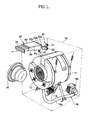
- a drum washing machine comprises: a cylindrical water tub 11 disposed in a machine body 10 for receiving wash water; and a cylindrical washing tub 12 rotatably disposed in the water tub 11, the washing tub 12 being provided at the circumferential part thereof with a plurality of water holes.
- a driving motor 13 for rotating the washing tub 12 disposed in the water tub 11 in alternating directions such that the washing tub 12 performs washing, rinsing, and dewatering operations.
- the water tub 11 and the washing tub 12 are provided at the front parts thereof with openings for allowing the laundry to be put into or removed from the washing tub 12 therethrough in the front of the machine body 10, respectively.
- a door 14 for opening and closing the openings.
- a water supply unit 20 which is connected to the water tub 11 via a water supply channel for supplying wash water into the water tub 11.
- a drainage unit 16 comprising a drain pipe 16a and drain pump 16b, for draining wash water in the water tub 11 out of the machine body 10 when the washing operation is completed.
- a detergent supply unit 30 for mixing a detergent in wash water to be supplied into the water tub 11 and supplying the wash water containing the detergent into the water tub 11.
- the water supply unit 20 comprises: water supply valves 21 and 22 connected to external water supply hoses (not shown) for controlling water supply; a plurality of water supply pipes 23a, 23b, and 23c connected between the water supply valves 21 and 22 and the detergent supply unit 30, the water supply pipes 23a, 23b, and 23c forming the water supply channel together with the external water supply hoses; and a connection pipe 24 for guiding wash water having passed through the detergent supply unit 30 into the water tub 11.
- the detergent supply unit 30 comprises: a box-shaped housing 40 having an opening 41 formed at the front part thereof; and a detergent container 70 separably inserted into the housing 40 through the opening 41 of the housing 40.
- the detergent supply unit 30 is mounted in the front upper part of the machine body 10 such that the detergent container 70 can be inserted into or withdrawn from the housing 40, in the same fashion as a drawer, in the front of the machine body 10.
- the housing 40 comprises: a lower case 50 having a detergent container accommodating space defined therein, the lower case 50 also having open front and upper parts thereof; and an upper case 60 attached to the upper part of the lower case 50 for covering the upper part of the lower case 50.
- the upper case 60 In the upper case 60 are formed a plurality of water supply channels 61 a, 61 b, and 61 c, which are divided from each other. At the rear part of the upper case 60 are formed a plurality of inlet ports 62a, 62b, and 62c, to which the water supply pipes 23a, 23b, and 23c are connected such that wash water is introduced into the water supply channel 61a, 61b, and 61c of the upper case 60. At the bottom of the upper case 60 are formed a plurality of through-holes 63 for distributing wash water introduced into the water supply channel 61a, 61 b, and 61 c over the detergent container 70.
- the lower case 50 is provided with an outlet port 51, which is formed at the rear part of the bottom of the lower case 50.
- the connection pipe 24 is connected to the outlet port 51 of the lower case 50 such that wash water introduced into the housing 40 is supplied into the water tub 11.
- the bottom of the lower case 50 is inclined downward toward the outlet port 51 such that wash water in the housing 40 easily flows to the outlet port 51.
- At the upper parts of both sides of the lower case 50 are disposed guide rails 52 for guiding insertion or withdrawal of the detergent container 70 into or from the lower case 50.
- the detergent container 70 has an open upper part and an open rear end.
- detergent input spaces 72, 73, and 74 which are divided from each other by a dividing wall 71, such that different kinds of detergents are individually put into the detergent input spaces 72, 73, and 74.
- the detergent input spaces 72, 73, and 74 are formed in the longitudinal direction of the detergent container 70 such that the detergent input spaces 72, 73, and 74 correspond to water supply channels 61a, 61b, and 61c, respectively.
- the bottom of the detergent container 70 is inclined downward from the front end to the rear end thereof.
- wash water supplied from the water supply unit 30 passes through the detergent input spaces 72, 73, and 74 before the wash water is introduced into the water tub 11. At this time, detergents, put in the detergent input spaces 72, 73, and 74, are mixed in the wash water passing through the detergent input spaces 72, 73, and 74, and therefore, wash water containing detergents is supplied into the water tub 11.
- wash water supplied into the detergent container 70 through the water supply channels 61 a, 61 b, and 61 c formed at the upper part of the housing 40, is introduced into the detergent input spaces 72, 73, and 74 from above the detergent input spaces 72, 73, and 74, and then flows to the rear parts of the detergent input spaces 72, 73, and 74 along the inclined bottoms of the detergent input spaces 72, 73, and 74.
- the detergents put in the detergent input spaces 72, 73, and 74, are mixed in the wash water.
- the wash water containing the detergents is supplied into the water tub 11 through the open rear ends of the detergent input spaces 72, 73, and 74 and the outlet port 51 of the housing 40.
- At least one of the detergent input spaces 72, 73, and 74 is configured such that a powdered or liquid detergent is selectively put into the detergent input space 74.
- the detergent input space 74 is disposed a control member 80, which is connected to both sides of the detergent input space 74, such that the control member 80 is moved downward to increase time for which the liquid detergent stays in the detergent input space 74 when the liquid detergent is put into the detergent input space 74 and such that the control member 80 is moved upward when the powdered detergent is put into the detergent input space 74.
- the control member 80 has a height less than that of the detergent input space 74.
- vertical movement guide grooves 74a are vertically formed at upper parts of both sides of the detergent input space 74 such that each of the vertical movement guide grooves 74a has a predetermined vertical length, and vertical movement guide protrusions 81 are formed at the upper parts of both ends of the control member 80.
- the vertical movement guide protrusions 81 of the control member 80 are engaged in the vertical movement guide grooves 74a of the detergent input space 74, respectively, such that the vertical movement guide protrusions 81 are moved vertically along the vertical movement guide grooves 74a for guiding the vertical movement of the control member 80.
- the control member 80 serves to control flow of the detergent in the detergent input space 74 to increase or decrease time for which the detergent stays in the detergent input space 74, allow the liquid or powdered detergent to be selectively put into the detergent input space 74, and uniformly mix the detergent put in the detergent input space 74 in wash water passing through the detergent container.
- the bottom of the detergent input space 74 is inclined downward toward the rear end thereof, and the rear end of the detergent input space 74 is open. Consequently, when the liquid detergent is put into the detergent input space 74, the liquid detergent immediately flows to the outlet port 51 of the housing 40. As a result, the liquid detergent is not uniformly mixed in wash water introduced into the detergent input space 74.
- the control member 80 is disposed in the detergent input space 74. Consequently, when the liquid detergent is put into the detergent input space 74, the control member 80 is moved downward for increasing time for which the liquid detergent stays in the detergent input space 74 in front of the control member 80.
- the liquid detergent is mixed in the wash water introduced into the detergent input space 74 in front of the control member 80, and then flows to the outlet port 51 of the housing 40 over the upper end of the control member 80.
- the liquid detergent put in the detergent input space 74 is uniformly mixed in the wash water introduced into the detergent input space 74, and is then supplied into the water tub 11.
- the control member 80 When the powdered detergent is put into the detergent input space 74, on the other hand, the control member 80 is moved upward such that the distance between the lower end of the control member 80 and the bottom of the detergent input space 74 is maximized. In this case, the powdered detergent put in the detergent input space 74 is uniformly mixed in the wash water introduced into the detergent input space 74, and is then smoothly supplied into the water tub 11.
- the vertical movement guide protrusions 81 When the control member 80 is maximally moved upward, the vertical movement guide protrusions 81 are positioned at the upper ends of the vertical movement guide grooves 74a, respectively. When the control member 80 is maximally moved downward, the vertical movement guide protrusions 81 are positioned at the lower ends of the vertical movement guide grooves 74a, respectively. Preferably, but not necessarily, the vertical movement guide protrusions 81 are tightly fitted in the vertical movement guide grooves 74a, respectively, such that the control member 80 is kept at the uppermost or lowermost position.
- the vertical movement guide protrusions 81 are preferably, but not necessarily, engaged in the vertical movement guide grooves 74a, respectively, such that the control member 80 is not rotated about the vertical movement guide protrusions 81 by the liquid detergent or the wash water in the detergent input space 74.
- control member 80 is disposed between the front end and the open rear end of the detergent input space 74, and the lower end of the control member 80 comes into contact with the bottom of the detergent input space 74 when the control member 80 is maximally moved downward such that the liquid detergent in the front of the control member 80 does not flow to the rear part of the detergent input space 74 before the wash water is supplied.
- control member 80 may be disposed adjacent to the open rear end of the detergent input space 74 such that the liquid detergent is fully accommodated in the detergent input space 74.
- control member 80 may be disposed such that the lower end of the control member 80 is spaced somewhat apart from the bottom of the detergent input space 74 when the control member 80 is maximally moved downward as long as it is satisfied for the liquid detergent in front of the control member 80 to stay for a predetermined period of time.
- the vertical movement guide protrusions 81 of the control member 80 are forcibly fitted into the vertical movement guide grooves 74a of the detergent input space 74, respectively, to dispose the control member 80 in the detergent input space 74 such that the control member 80 is movable vertically. Thereafter, the detergent container 70 is inserted into the housing 40.
- the user When a user wants to put a liquid detergent into the detergent container 70, the user withdraws the detergent container 70 from the housing 40, and then pushes the control member 80 disposed in the detergent input space 74 downward such that the control member 80 is moved downward until the lower end of the control member 80 comes into contact with the bottom of the detergent input space 74.
- the vertical movement guide protrusions 81 of the control member 80 are positioned at the lower ends of the vertical movement guide grooves 74a, respectively, which is maintained until the user pulls the control member 80 upward.
- the user After the user puts the liquid detergent into the detergent input space 74 in front of the control member 80, the user inserts the detergent container 70 into the housing 40. At this time, the liquid detergent put in the detergent input space 74 in front of the control member 80 stays in the detergent input space 74 and does not immediately flow to the rear part of the detergent input space 74.
- the wash water supplied through the water supply valves 21 and 22, is introduced into the detergent supply unit 30 through the water supply pipes 23a, 23b, and 23c and the inlet ports 62a, 62b, and 62c of the detergent supply unit 30.
- the wash water introduced into the detergent supply unit 30 is injected into the detergent input space 74 through one of the water supply channels 61a, 61b, and 61c.
- the liquid detergent in the detergent input space 74 is uniformly mixed in the wash water introduced into the detergent input space 74 in front of the control member 80, flows to the rear part of the detergent container 70 over the upper end of the control member 80, and is then supplied into the water tub 11 through the outlet port 51 of the housing 40.
- the user When the user wants to put a powdered detergent into the detergent container 70, the user withdraws the detergent container 70 from the housing 40, and then pulls the control member 80 disposed in the detergent input space 74 upward such that the lower end of the control member 80 is maximally spaced apart from the bottom of the detergent input space 74. At this time, the vertical movement guide protrusions 81 of the control member 80 are positioned at the upper ends of the vertical movement guide grooves 74a, respectively, which is maintained until the user pushes the control member 80 downward.
- the user After the user puts the powdered detergent into the detergent input space 74, the user inserts the detergent container 70 into the housing 40.
- the powdered detergent in the detergent input space 74 is uniformly mixed in the wash water introduced into the detergent input space 74, flows to the rear part of the detergent container 70, and is then supplied into the water tub 11.
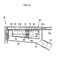
- FIGS. 6 to 11 show a detergent supply unit according to a second exemplary embodiment of the present invention.
- the second exemplary embodiment is identical to the first exemplary embodiment except for a structural change of the control member and modification of the detergent input space according to the structural change of the control member. Accordingly, components of the detergent supply unit according to the second exemplary embodiment, which correspond to those of the detergent supply unit according to the first exemplary embodiment, are indicated by the same reference numerals as those of the detergent supply unit according to the first exemplary embodiment.
- the detergent input space 74 is configured such that a powdered or liquid detergent is selectively put into the detergent input space 74.
- a control member 180 which is connected to both sides of the detergent input space 74, such that the control member 180 is moved downward to increase time for which the liquid detergent stays in the detergent input space 74 when the liquid detergent is put into the detergent input space 74 and such that the control member 180 is moved upward when the powdered detergent is put into the detergent input space 74.
- separation-preventing members 90 are disposed at both sides of the detergent input space 74, for preventing the control member 180 from being separated from the detergent input space 74.
- the separation-preventing members 90 are configured to surround both ends of the control member 180 while the control member 180 is movable vertically.
- the separation-preventing members 90 extend inward from both sides of the detergent input space 74.
- Each of the separation-preventing members 90 comprises: an upper rib 91 for supporting the upper end of the control member 180 maximally moved upward to prevent the control member 180 from being separated from the detergent input space 74; a first side rib 92 disposed in front of or at the rear of the control member 180 for preventing the control member 180 from being separated from the detergent input space 74; and a second side rib 93 disposed at the rear or in front of the control member 180 for preventing the control member 180 from being separated from the detergent input space 74.
- the first side rib 92 is disposed in front of the control member 180
- the second side rib 93 is disposed at the rear of the control member 180.
- each of the vertical movement guide grooves 75 has a predetermined vertical length.
- the control member 180 is provided at the upper parts of both ends thereof with vertical movement guide protrusions 182a, which are engaged in the vertical movement guide grooves 75 such that the vertical movement guide protrusions 182a are guided vertically along the vertical movement guide grooves 75 when the control member 180 is moved vertically.
- the liquid detergent When the liquid detergent is put into the detergent input space 74, which is formed such that the bottom of the detergent input space 74 is inclined downward to the rear part of the detergent input space 74, and the rear end of the detergent input space 74 is open, the liquid detergent immediately flows to the outlet port 51 of the housing 40. As a result, the liquid detergent is not uniformly mixed in wash water introduced into the detergent input space 74.
- the control member 180 is moved downward, when the liquid detergent is put into the detergent input space 74, such that the liquid detergent stays in the detergent input space 74 in front of the control member 180.
- the liquid detergent is mixed in the wash water introduced into the detergent input space 74 in front of the control member 180, and then flows to the outlet port 51 of the housing 40 over the upper end of the control member 180. In this way, the liquid detergent put in the detergent input space 74 is uniformly mixed in the wash water introduced into the detergent input space 74, and is then supplied into the water tub 11.
- the control member 180 When the powdered detergent is put into the detergent input space 74, on the other hand, the control member 180 is moved upward such that the distance between the lower end of the control member 180 and the bottom of the detergent input space 74 is maximized. In this case, the powdered detergent put in the detergent input space 74 is uniformly mixed in the wash water introduced into the detergent input space 74, and is then smoothly supplied into the water tub 11.
- the control member 180 comprises a vertical-moving plate 181, having both ends supported by both sides of the detergent input space 74, for preventing the liquid detergent from flowing toward the outlet port 51 of the housing 40.
- the vertical-moving plate 181 comes into contact with the bottom of the detergent input space 74 for preventing the liquid detergent from flowing toward the outlet port 51 of the housing 40.
- a gap-forming part 181 a for forming a predetermined gap between the vertical-moving plate 181 and the bottom of the detergent input space 74 while the vertical-moving plate 181 is in contact with the bottom of the detergent input space 74.
- the gap is formed such that, after most of the liquid detergent is supplied into the water tub 11 while being mixed in the wash water, the rest of the liquid detergent, which is left on the bottom of the detergent input space 74 in front of the control member 180 can be discharged out of the detergent input space 74. If the gap is too large, a large portion of the liquid detergent may flow out of the detergent input space 74 before the wash water is supplied. Consequently, the gap-forming part 181a is preferably, but not necessarily, configured such that the liquid detergent stays in the detergent input space 74 in front of the control member 180 for more than a predetermined period of time.
- Each of the vertical movement guide grooves 75 comprises: an upper end groove 75a formed at the upper end thereof for allowing the corresponding vertical movement guide protrusion 182a to be positioned therein when the control member 180 is maximally moved upward; a lower end groove 75c formed at the lower end thereof for allowing the corresponding vertical movement guide protrusion 182a to be positioned therein when the control member 180 is maximally moved downward; and a connection groove 75b connected between the upper end groove 75a and the lower end groove 75c.
- the upper end groove 75a and the lower end groove 75c are depressed more deeply than the connection groove 75b such that the vertical movement guide protrusion 182a is kept positioned in the upper end groove 75a or the lower end groove 75c when the control member 180 is maximally moved upward or downward.
- slope parts 75d are formed at the lower end part of the upper end groove 75a and the upper end part of the lower end groove 75c, respectively, which are inclined toward the connection groove 75b for smoothly guiding the movement of the vertical movement guide protrusion 182a to the connection groove 75b.
- protrusion-forming plates 182 are formed at both sides of the upper rear surface of the vertical-moving plate 181 at both sides of the detergent input space 74 such that the vertical movement guide protrusions 182a are formed at the protrusion-forming plates 182, respectively.
- cutout parts 182b are formed at the protrusion-forming plates 182b for maintaining the vertical movement guide protrusions 182a in a flexible state.
- the vertical movement guide protrusions 182a When the control member 180 is maximally moved upward or downward, the vertical movement guide protrusions 182a are positioned in the upper end groove 75a and the lower end groove 75c, which are depressed more deeply than the connection groove 75b. Consequently, the control member 180 is maintained in a fixed state until the user forcibly moves the control member 180 in the opposite direction.
- the vertical movement guide protrusions 182a When the user moves the control member 180, which is maximally moved upward or downward, in the opposite direction, the vertical movement guide protrusions 182a are smoothly moved to the connection groove 75b from the upper end groove 75a and the lower end groove 75c along the slope parts 75d while being pushed toward the insides of the protrusion-forming plates 182 by the cutout parts 182b. In this way, the control member 180 is easily moved in the opposite direction.
- the control member 180 further comprises: a push plate 183 having the upper end connected to the upper end of the vertical-moving plate 181 and the lower part vertically extending while being spaced apart from the vertical-moving plate 181 such that the push plate 183 is elastically supported by the first side ribs 92.
- a push plate 183 having the upper end connected to the upper end of the vertical-moving plate 181 and the lower part vertically extending while being spaced apart from the vertical-moving plate 181 such that the push plate 183 is elastically supported by the first side ribs 92.
- the control member 180 is placed in the uppermost position when the control member 180 is disposed in the separation-preventing members 90 through the engagement of the push plate 183 with the step-shaped parts 92a.
- the push plate 183 is pushed toward the vertical-moving plate 181 to disengage the push plate 183 from the step-shaped parts 92a in this state, it is possible to move the control member 180 downward such that the control member 180 is placed in the lowermost position.
- a holding plate 184 for connecting the upper ends of the protrusion-forming plates 182.
- control member 180 is disposed between the front end and the open rear end of the detergent input space 74.
- control member 180 may be disposed adjacent to the open rear end of the detergent input space 74 such that the liquid detergent is fully accommodated in the detergent input space 74.
- the lower parts of the protrusion-forming plates 182, which are below the vertical movement guide protrusions 182a, are positioned under the upper ribs 91 of the separation-preventing members 90, respectively, and the vertical movement guide protrusions 182a are supported by the upper ends of the upper ribs 91, respectively.
- the control member 180 is pushed downward in this state, both ends of the control member 180 enter the separation-preventing members 90, respectively.
- the control member 180 is securely disposed in the detergent input space 74.
- the push plate 183 is supported by the step-shaped parts 92a, and the vertical movement guide protrusions 182a are inserted into the upper end grooves 75a of the vertical movement guide grooves 75.
- the control member 180 is placed in the uppermost position such that a powdered detergent is put into the detergent input space 74.
- the user When the user wants to put a liquid detergent into the detergent input space 74, the user withdraws the detergent container 70 from the housing 40, and then pushes the push plate 183 toward the vertical-moving plate 181 such that the lower end of the push plate 183 is disengaged from the step-shaped parts 92a of the first side ribs 92. After that, the user pushes the control member 180 downward. At this time, the vertical movement guide protrusions 182a, positioned in the upper end grooves 75a of the vertical movement guide grooves 75, are smoothly moved to the lower end grooves 75c along the slope parts 75d and the connection grooves 75b while being pushed toward the insides of the protrusion-forming plates 182.
- the lower end of the vertical-moving plate 181 comes into contact with the bottom of the detergent input space 74.
- the vertical movement guide protrusions 182a pushed toward the insides of the protrusion-forming plates 182, are returned to their original positions, and therefore, the vertical movement guide protrusions 182a are inserted into the lower end grooves 75c of the vertical movement guide grooves 75.
- the control member 180 is placed in the lowermost position where the liquid detergent is put into the detergent input space 74, as shown in FIGS. 8 and 9.
- the user After the user puts the liquid detergent into the detergent input space 74 in front of the control member 180, the user inserts the detergent container 70 into the housing 40. At this time, the liquid detergent put in the detergent input space 74 in front of the control member 180 stays in the detergent input space 74 and does not immediately flow to the rear part of the detergent input space 74.
- the wash water supplied through the water supply valves 21 and 22, is introduced into the detergent supply unit 30 through the water supply pipes 23a, 23b, and 23c and the inlet ports 62a, 62b, and 62c of the detergent supply unit 30.
- the wash water introduced into the detergent supply unit 30 is injected into the detergent input space 74 through one of the water supply channels 61 a, 61 b, and 61c.
- the liquid detergent in the detergent input space 74 is uniformly mixed in the wash water introduced into the detergent input space 74 in front of the control member 180, flows to the rear part of the detergent container 70 over the upper end of the control member 180, and is then supplied into the water tub 11 through the outlet port 51 of the housing 40.
- the rest of the liquid detergent is left on the bottom of the detergent input space 74 in front of the control member 180.
- the rest of the liquid detergent is discharged out of the detergent input space 74 through the gap defined between the gap-forming part 181a formed at the middle part of the lower end of the vertical-moving plate 181 and the bottom of the detergent input space 74.
- the user When the user wants to put a powdered detergent into the detergent input space 74, the user withdraws the detergent container 70 from the housing 40, and then pulls the control member 180 upward. At this time, the vertical movement guide protrusions 182a, positioned in the lower end grooves 75a of the vertical movement guide grooves 75, are smoothly moved to the upper end grooves 75a along the slope parts 75d and the connection grooves 75b while being pushed toward the insides of the protrusion-forming plates 182. As a result, the lower end of the push plate 183 is supported by the step-shaped parts 92a of the first side ribs 92.
- the vertical movement guide protrusions 182a pushed toward the insides of the protrusion-forming plates 182, are returned to their original positions, and therefore, the vertical movement guide protrusions 182a are inserted into the upper end grooves 75a of the vertical movement guide grooves 75.
- the control member 180 is placed in the uppermost position where the powdered detergent is put into the detergent input space 74, as shown in FIGS. 10 and 11.
- the user After the user puts the powdered detergent into the detergent input space 74, the user inserts the detergent container 70 into the housing 40.
- the powdered detergent in the detergent input space 74 is uniformly mixed in the wash water introduced into the detergent input space 74, flows to the rear part of the detergent container 70, and is then supplied into the water tub 11.
- embodiments of the present invention provide a washing machine with a detergent supply unit, which has a control member that is movable downward to increase time for which a liquid detergent stays in a detergent input space when the liquid detergent is put into the detergent input space and is movable upward when a powdered detergent is put into the detergent input space. Consequently, embodiments of the present invention have the effect of selectively putting the powdered or liquid detergent into the same detergent input space and uniformly mixing the powdered or liquid detergent in wash water introduced into the detergent input space.
Landscapes
- Engineering & Computer Science (AREA)
- Textile Engineering (AREA)
- Detail Structures Of Washing Machines And Dryers (AREA)
Applications Claiming Priority (6)
| Application Number | Priority Date | Filing Date | Title |
|---|---|---|---|
| KR2004043784 | 2004-06-14 | ||
| KR1020040043784A KR100753440B1 (ko) | 2004-06-14 | 2004-06-14 | 세제공급장치를 갖춘 세탁기 |
| KR20040044041 | 2004-06-15 | ||
| KR2004044041 | 2004-06-15 | ||
| KR2004091029 | 2004-11-09 | ||
| KR1020040091029A KR101139247B1 (ko) | 2004-06-15 | 2004-11-09 | 세제공급장치를 갖춘 세탁기 |
Publications (2)
| Publication Number | Publication Date |
|---|---|
| EP1607508A2 true EP1607508A2 (fr) | 2005-12-21 |
| EP1607508A3 EP1607508A3 (fr) | 2007-06-27 |
Family
ID=34941241
Family Applications (1)
| Application Number | Title | Priority Date | Filing Date |
|---|---|---|---|
| EP05252888A Withdrawn EP1607508A3 (fr) | 2004-06-14 | 2005-05-11 | Machine à laver avec distributeur de détergent correspondant |
Country Status (3)
| Country | Link |
|---|---|
| US (1) | US20050274155A1 (fr) |
| EP (1) | EP1607508A3 (fr) |
| JP (1) | JP4137916B2 (fr) |
Cited By (5)
| Publication number | Priority date | Publication date | Assignee | Title |
|---|---|---|---|---|
| WO2011023808A1 (fr) * | 2009-08-31 | 2011-03-03 | Arcelik Anonim Sirketi | Machine à laver à distributeur d'agent de nettoyage |
| ITRN20100078A1 (it) * | 2010-12-21 | 2012-06-22 | Indesit Co Spa | Elettrodomestico |
| EP2374926A4 (fr) * | 2008-11-17 | 2013-11-20 | Lg Electronics Inc | Lave-linge |
| EP3158123A4 (fr) * | 2014-06-23 | 2017-11-22 | LG Electronics Inc. | Dispositif d'alimentation en détergent pour machine à laver |
| US10648119B2 (en) | 2016-05-30 | 2020-05-12 | Lg Electronics Inc. | Laundry treatment apparatus |
Families Citing this family (12)
| Publication number | Priority date | Publication date | Assignee | Title |
|---|---|---|---|---|
| DE102006029953A1 (de) * | 2006-06-29 | 2008-01-03 | BSH Bosch und Siemens Hausgeräte GmbH | Waschmaschine mit einem steuerbaren Frischwasserzulauf und Verfahren zum Betreiben einer solchen Waschmaschine |
| US20090095029A1 (en) * | 2007-10-10 | 2009-04-16 | Serge Gelinas | Laundry washing machine with automatic laundry products dispensing |
| KR101037156B1 (ko) * | 2008-11-17 | 2011-05-26 | 엘지전자 주식회사 | 세탁물 처리기기 |
| US20100161143A1 (en) * | 2008-12-18 | 2010-06-24 | Christopher Lawrence Smith | Dispensing system |
| JP6039377B2 (ja) * | 2012-11-20 | 2016-12-07 | シャープ株式会社 | イオン溶出装置、イオンカートリッジ、それらを備える洗濯機 |
| JP6156771B2 (ja) * | 2014-03-31 | 2017-07-05 | パナソニックIpマネジメント株式会社 | 洗濯機 |
| US10648121B2 (en) * | 2016-11-17 | 2020-05-12 | Whirlpool Corporation | Laundry treating appliance and dispenser |
| EP3617379B1 (fr) | 2018-08-30 | 2021-08-04 | Electrolux Appliances Aktiebolag | Appareil de traitement du linge comprenant un tiroir amélioré |
| US12043942B2 (en) | 2020-01-24 | 2024-07-23 | Midea Group Co., Ltd. | Dispenser for a laundry washing machine with overflow configuration |
| US11421368B2 (en) | 2020-01-24 | 2022-08-23 | Midea Group Co., Ltd. | Dispenser for a laundry washing machine |
| CN113818214B (zh) * | 2020-06-19 | 2024-07-16 | 青岛海尔洗衣机有限公司 | 一种洗涤剂溶解装置及洗衣机 |
| CN113818212B (zh) * | 2020-06-19 | 2024-08-27 | 青岛海尔洗衣机有限公司 | 一种洗涤剂盒组件及洗衣机 |
Family Cites Families (7)
| Publication number | Priority date | Publication date | Assignee | Title |
|---|---|---|---|---|
| DE3608620A1 (de) * | 1986-03-14 | 1987-09-24 | Bosch Siemens Hausgeraete | Waschmaschine mit einer waschmittel-einspuelschale |
| DE3608619A1 (de) * | 1986-03-14 | 1987-09-17 | Bosch Siemens Hausgeraete | Waschmaschine mit einer waschmittel-einspuelschale |
| DE4325821A1 (de) * | 1993-07-31 | 1995-02-02 | Foron Waschgeraete Gmbh | Einrichtung zum Einspülen von Wasch- und/oder Pflegemitteln in Wasch- oder Geschirrspülmaschinen |
| DE19505734A1 (de) * | 1995-02-20 | 1996-08-22 | Bosch Siemens Hausgeraete | Waschmittel-Einspüleinrichtung für eine Haushaltwaschmaschine |
| TW366015U (en) * | 1997-08-16 | 1999-08-01 | Samsung Electronics Co Ltd | Filter for a washing machine |
| ES2280288T3 (es) * | 2001-09-14 | 2007-09-16 | Whirlpool Corporation | Lavadora o lavavajillas automaticos con distribuidor de agua. |
| DE20208189U1 (de) * | 2002-05-25 | 2002-08-08 | Whirlpool Corp., Benton Harbor, Mich. | Waschmittel-Einspülschale für eine Waschmaschine |
-
2005
- 2005-05-11 EP EP05252888A patent/EP1607508A3/fr not_active Withdrawn
- 2005-05-12 US US11/127,194 patent/US20050274155A1/en not_active Abandoned
- 2005-06-07 JP JP2005167515A patent/JP4137916B2/ja not_active Expired - Fee Related
Cited By (11)
| Publication number | Priority date | Publication date | Assignee | Title |
|---|---|---|---|---|
| EP2374926A4 (fr) * | 2008-11-17 | 2013-11-20 | Lg Electronics Inc | Lave-linge |
| US9297106B2 (en) | 2008-11-17 | 2016-03-29 | Lg Electronics Inc. | Washing machine having a detergent box with a partitioning member |
| WO2011023808A1 (fr) * | 2009-08-31 | 2011-03-03 | Arcelik Anonim Sirketi | Machine à laver à distributeur d'agent de nettoyage |
| ITRN20100078A1 (it) * | 2010-12-21 | 2012-06-22 | Indesit Co Spa | Elettrodomestico |
| WO2012085827A3 (fr) * | 2010-12-21 | 2013-11-14 | Indesit Company S.P.A. | Appareil ménager électrique |
| RU2606704C2 (ru) * | 2010-12-21 | 2017-01-10 | Индезит Компани С.П.А. | Бытовой электроприбор |
| EP3158123A4 (fr) * | 2014-06-23 | 2017-11-22 | LG Electronics Inc. | Dispositif d'alimentation en détergent pour machine à laver |
| US10508381B2 (en) | 2014-06-23 | 2019-12-17 | Lg Electronics Inc. | Detergent feeding device for washer |
| US10648119B2 (en) | 2016-05-30 | 2020-05-12 | Lg Electronics Inc. | Laundry treatment apparatus |
| US11208754B2 (en) | 2016-05-30 | 2021-12-28 | Lg Electronics Inc. | Laundry treatment apparatus |
| EP3252205B1 (fr) * | 2016-05-30 | 2022-07-06 | LG Electronics Inc. | Appareil de traitement de linge |
Also Published As
| Publication number | Publication date |
|---|---|
| US20050274155A1 (en) | 2005-12-15 |
| EP1607508A3 (fr) | 2007-06-27 |
| JP2006000627A (ja) | 2006-01-05 |
| JP4137916B2 (ja) | 2008-08-20 |
Similar Documents
| Publication | Publication Date | Title |
|---|---|---|
| EP1607508A2 (fr) | Machine à laver avec distributeur de détergent correspondant | |
| EP1463854B1 (fr) | Dispositif d'alimentation en detergent pour lave-linge | |
| KR101082563B1 (ko) | 드럼 세탁기의 세제박스 | |
| JP3927542B2 (ja) | 洗濯機の洗剤投入装置 | |
| JP4137919B2 (ja) | 洗剤供給装置を備えた洗濯機 | |
| US20140091112A1 (en) | Detergent supply apparatus and washing machine having the same | |
| EP1795643A1 (fr) | Distributeur de détergent pour une machine à laver | |
| AU2023222923B2 (en) | Laundry treating apparatus | |
| US8733133B2 (en) | Washing machine and drawer assembly thereof | |
| KR20140027849A (ko) | 세제공급장치를 가지는 세탁기 | |
| KR100753440B1 (ko) | 세제공급장치를 갖춘 세탁기 | |
| KR101013374B1 (ko) | 세제공급장치를 갖춘 세탁기 | |
| KR20200091244A (ko) | 의류처리장치 | |
| KR100830487B1 (ko) | 드럼세탁기의 세제 공급장치 | |
| JP7704381B2 (ja) | 分配器ボックス、洗剤投入装置、洗濯機器、洗濯機器セット | |
| KR101022224B1 (ko) | 세제공급장치를 갖춘 세탁기 | |
| KR20150063263A (ko) | 세탁기 | |
| CN100585053C (zh) | 洗衣机的洗涤剂供应装置 | |
| KR101544760B1 (ko) | 세제공급장치 및 이를 포함하는 세탁기 | |
| KR101579095B1 (ko) | 세탁물 처리기기 | |
| KR101034194B1 (ko) | 세제공급장치를 갖춘 세탁기 | |
| RU2293151C1 (ru) | Узел для подачи моющего средства стиральной машины | |
| KR101028082B1 (ko) | 드럼 세탁기의 세제박스 록킹구조 | |
| KR20070059426A (ko) | 세탁기의 세제공급기구 | |
| KR102892372B1 (ko) | 세탁기 및 세탁기용 필터 장치 |
Legal Events
| Date | Code | Title | Description |
|---|---|---|---|
| PUAI | Public reference made under article 153(3) epc to a published international application that has entered the european phase |
Free format text: ORIGINAL CODE: 0009012 |
|
| AK | Designated contracting states |
Kind code of ref document: A2 Designated state(s): AT BE BG CH CY CZ DE DK EE ES FI FR GB GR HU IE IS IT LI LT LU MC NL PL PT RO SE SI SK TR |
|
| AX | Request for extension of the european patent |
Extension state: AL BA HR LV MK YU |
|
| PUAL | Search report despatched |
Free format text: ORIGINAL CODE: 0009013 |
|
| AK | Designated contracting states |
Kind code of ref document: A3 Designated state(s): AT BE BG CH CY CZ DE DK EE ES FI FR GB GR HU IE IS IT LI LT LU MC NL PL PT RO SE SI SK TR |
|
| AX | Request for extension of the european patent |
Extension state: AL BA HR LV MK YU |
|
| 17P | Request for examination filed |
Effective date: 20071105 |
|
| AKX | Designation fees paid |
Designated state(s): DE FR GB IT NL |
|
| STAA | Information on the status of an ep patent application or granted ep patent |
Free format text: STATUS: THE APPLICATION HAS BEEN WITHDRAWN |
|
| 18W | Application withdrawn |
Effective date: 20090213 |