EP1607604A1 - Procédé informatique de calcul du taux de dégagement de chaleur (HRR) dans un moteur à combustion interne avec un système d'injection à rampe commune - Google Patents
Procédé informatique de calcul du taux de dégagement de chaleur (HRR) dans un moteur à combustion interne avec un système d'injection à rampe commune Download PDFInfo
- Publication number
- EP1607604A1 EP1607604A1 EP04425398A EP04425398A EP1607604A1 EP 1607604 A1 EP1607604 A1 EP 1607604A1 EP 04425398 A EP04425398 A EP 04425398A EP 04425398 A EP04425398 A EP 04425398A EP 1607604 A1 EP1607604 A1 EP 1607604A1
- Authority
- EP
- European Patent Office
- Prior art keywords
- hrr
- engine
- heat
- combustion
- establishing
- Prior art date
- Legal status (The legal status is an assumption and is not a legal conclusion. Google has not performed a legal analysis and makes no representation as to the accuracy of the status listed.)
- Granted
Links
- 238000004364 calculation method Methods 0.000 title claims abstract description 5
- 230000017525 heat dissipation Effects 0.000 title description 6
- 238000012360 testing method Methods 0.000 claims abstract description 27
- 238000013528 artificial neural network Methods 0.000 claims abstract description 22
- 238000004422 calculation algorithm Methods 0.000 claims abstract description 21
- 238000000034 method Methods 0.000 claims abstract description 19
- 238000004458 analytical method Methods 0.000 claims abstract description 7
- 238000002347 injection Methods 0.000 claims description 58
- 239000007924 injection Substances 0.000 claims description 58
- 238000002485 combustion reaction Methods 0.000 claims description 44
- 239000000446 fuel Substances 0.000 claims description 22
- 235000000334 grey box Nutrition 0.000 claims description 9
- 244000085685 grey box Species 0.000 claims description 9
- 238000013461 design Methods 0.000 abstract description 3
- 230000008569 process Effects 0.000 description 8
- 239000012530 fluid Substances 0.000 description 7
- 238000004088 simulation Methods 0.000 description 6
- 230000003068 static effect Effects 0.000 description 6
- 238000012549 training Methods 0.000 description 6
- 238000013459 approach Methods 0.000 description 4
- 239000000203 mixture Substances 0.000 description 4
- 239000000243 solution Substances 0.000 description 3
- NYTOUQBROMCLBJ-UHFFFAOYSA-N Tetranitromethane Chemical compound [O-][N+](=O)C([N+]([O-])=O)([N+]([O-])=O)[N+]([O-])=O NYTOUQBROMCLBJ-UHFFFAOYSA-N 0.000 description 2
- 230000015572 biosynthetic process Effects 0.000 description 2
- 238000006243 chemical reaction Methods 0.000 description 2
- 230000006835 compression Effects 0.000 description 2
- 238000007906 compression Methods 0.000 description 2
- 238000011217 control strategy Methods 0.000 description 2
- 239000011159 matrix material Substances 0.000 description 2
- 230000001404 mediated effect Effects 0.000 description 2
- 238000012545 processing Methods 0.000 description 2
- 238000011160 research Methods 0.000 description 2
- 238000000889 atomisation Methods 0.000 description 1
- 230000033228 biological regulation Effects 0.000 description 1
- 230000003197 catalytic effect Effects 0.000 description 1
- 238000012512 characterization method Methods 0.000 description 1
- 238000000354 decomposition reaction Methods 0.000 description 1
- 238000011161 development Methods 0.000 description 1
- 238000010586 diagram Methods 0.000 description 1
- 239000003344 environmental pollutant Substances 0.000 description 1
- 238000001704 evaporation Methods 0.000 description 1
- 230000008020 evaporation Effects 0.000 description 1
- 238000000605 extraction Methods 0.000 description 1
- 230000003993 interaction Effects 0.000 description 1
- 239000007788 liquid Substances 0.000 description 1
- 238000002156 mixing Methods 0.000 description 1
- 210000002569 neuron Anatomy 0.000 description 1
- 238000007254 oxidation reaction Methods 0.000 description 1
- 239000002245 particle Substances 0.000 description 1
- 231100000719 pollutant Toxicity 0.000 description 1
- 238000004321 preservation Methods 0.000 description 1
- 230000009467 reduction Effects 0.000 description 1
- 230000003019 stabilising effect Effects 0.000 description 1
- 239000000126 substance Substances 0.000 description 1
- 238000003786 synthesis reaction Methods 0.000 description 1
- 238000009834 vaporization Methods 0.000 description 1
- 239000002699 waste material Substances 0.000 description 1
Images






Classifications
-
- F—MECHANICAL ENGINEERING; LIGHTING; HEATING; WEAPONS; BLASTING
- F02—COMBUSTION ENGINES; HOT-GAS OR COMBUSTION-PRODUCT ENGINE PLANTS
- F02D—CONTROLLING COMBUSTION ENGINES
- F02D41/00—Electrical control of supply of combustible mixture or its constituents
- F02D41/30—Controlling fuel injection
- F02D41/38—Controlling fuel injection of the high pressure type
- F02D41/3809—Common rail control systems
-
- F—MECHANICAL ENGINEERING; LIGHTING; HEATING; WEAPONS; BLASTING
- F02—COMBUSTION ENGINES; HOT-GAS OR COMBUSTION-PRODUCT ENGINE PLANTS
- F02D—CONTROLLING COMBUSTION ENGINES
- F02D35/00—Controlling engines, dependent on conditions exterior or interior to engines, not otherwise provided for
- F02D35/02—Controlling engines, dependent on conditions exterior or interior to engines, not otherwise provided for on interior conditions
- F02D35/023—Controlling engines, dependent on conditions exterior or interior to engines, not otherwise provided for on interior conditions by determining the cylinder pressure
-
- F—MECHANICAL ENGINEERING; LIGHTING; HEATING; WEAPONS; BLASTING
- F02—COMBUSTION ENGINES; HOT-GAS OR COMBUSTION-PRODUCT ENGINE PLANTS
- F02D—CONTROLLING COMBUSTION ENGINES
- F02D41/00—Electrical control of supply of combustible mixture or its constituents
- F02D41/02—Circuit arrangements for generating control signals
- F02D41/14—Introducing closed-loop corrections
- F02D41/1401—Introducing closed-loop corrections characterised by the control or regulation method
- F02D41/1405—Neural network control
-
- F—MECHANICAL ENGINEERING; LIGHTING; HEATING; WEAPONS; BLASTING
- F02—COMBUSTION ENGINES; HOT-GAS OR COMBUSTION-PRODUCT ENGINE PLANTS
- F02D—CONTROLLING COMBUSTION ENGINES
- F02D2200/00—Input parameters for engine control
- F02D2200/02—Input parameters for engine control the parameters being related to the engine
- F02D2200/06—Fuel or fuel supply system parameters
- F02D2200/0625—Fuel consumption, e.g. measured in fuel liters per 100 kms or miles per gallon
-
- F—MECHANICAL ENGINEERING; LIGHTING; HEATING; WEAPONS; BLASTING
- F02—COMBUSTION ENGINES; HOT-GAS OR COMBUSTION-PRODUCT ENGINE PLANTS
- F02D—CONTROLLING COMBUSTION ENGINES
- F02D41/00—Electrical control of supply of combustible mixture or its constituents
- F02D41/30—Controlling fuel injection
- F02D41/38—Controlling fuel injection of the high pressure type
- F02D41/40—Controlling fuel injection of the high pressure type with means for controlling injection timing or duration
- F02D41/402—Multiple injections
- F02D41/403—Multiple injections with pilot injections
Definitions
- the present invention relates to a soft-computing method for establishing the heat dissipation law in a diesel Common Rail engine, in particular for establishing the heat dissipation mean speed (HRR).
- HRR heat dissipation mean speed
- the invention relates to a system for realising a grey box model, able to anticipate the trend of the combustion process in a Diesel Common Rail engine, when the rotation speed and the parameters characterising the fuel injection strategy vary.
- Map control systems are known for associating a fuel injection strategy with the load demand of a driver which represents the best compromise between the following contrasting aims: maximisation of the torque, minimization of the consumption, reduction of the noise, cut down of the NOx and of the carbonaceous particulate.
- the characteristic of this control is that of associating a set of parameters (param 1 ,..., param n ) to the driver demand which describe the best fuel injection strategy according to the rotation speed of the driving shaft and of other sizes.
- the domain of the function in (1) is the size space ⁇ 2 since the rotation speed and the driver demand can take infinite values in the continuous.
- the discretization of the speed and driverDemand variables allows to transform the function in (1) (param 1 ,..., param n ) into a set of n matrixes, called control maps.
- the procedure for constructing the control maps initially consists in establishing maps sizes, i.e. the number of rows and columns of the matrixes.
- the optimal injection strategy is determined, on the basis of experimental tests.
- Figure 2 shows a simple map injection control scheme relating to the engine at issue.
- the real-time choice of the injection strategy occurs through a linear interpolation among the parameter values (param 1 ,..., param n ) contained in the maps.
- the map injection control is a static, open control system.
- the system is static since the control maps are off-line determined through a non sophisticated processing of the data gathered during the experimental tests; the control maps do not provide an on-line update of the contained values.
- the system moreover, is open since the injection law, obtained by the interpolation of the matrix values among which the driver demand shows up, is not monitored, i.e. it is not verified that the NOx and carbonaceous particulate emissions, corresponding to the current injection law, do not exceed the safety levels and that the corresponding torque is close or not to the driver demand.
- the explanatory example of figure 3 represents a typical map, static and open, injection control.
- a dynamic, closed map control is obtained by adding to the static, open system: a model providing some operation parameters of the engine when the considered injection strategy varies, a threshold set relative to the operation parameters and finally a set of rules (possibly fuzzy rules) for updating the current injection law and/or the values contained in the control maps of the system.
- Figure 4 describes the block scheme of a traditional dynamic, closed, map control.
- a model of the combustion process in a Diesel engine requires a simulation meeting a series of complex processes: the air motion in the cylinder, the atomisation and vaporisation of the fuel, the mixture of the two fluids, the reaction kinetics which regulates the premixed and diffusive steps of the combustion.
- the multidimensional models try to provide all the fluid dynamic details of the phenomena intervening in the cylinder of a Diesel, such as: motion equations of the air inside the cylinder, the evolution of the fuel and the interaction thereof with the air, the evaporation of the liquid particles and the development of the chemical reactions responsible for the pollutants formation.
- thermodynamic models make use of the first principle of the thermodynamics and of correlations of the empirical type for a physical but synthetic description of different processes implied in the combustion, for this reason they are also called phenomenological.
- the fluid can be considered of spatially uniform composition, temperature and pressure, i.e. variable only with time (i.e. functions only of the crank angle).
- the model is referred to as "single area” model, whereas the "multi-area” ones take into account the space uneveness typical of the combustion of a Diesel engine.
- the starting base for modelling the combustion process in an engine is the first principle of the thermodynamics applied to the gaseous system contained in the combustion chamber.
- the operation fluid can be considered homogeneous in composition, temperature and pressure, suitably choosing the relevant mean values of the sizes.
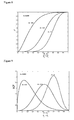
- the combustible mass fraction x b ( ⁇ ) has an S-like form being approximable with sufficient precision by an exponential function (Wiebe function) of the type: with a suitable choice of the parameters a and m.
- the parameter a called efficiency parameter, measures the completeness of the combustion process.
- the simplest way to simulate the combustion process in a Diesel engine consists in supposing the law the burnt fuel fraction varies with is known.
- the x b can be determined either with points, on the basis of the processing of experimental surveys, or by the analytical via through a Wiebe function.
- the analytical approach has several limits. First of all, it is necessary to determine the parameters describing the Wiebe function for different operation conditions of the engine.
- ⁇ represents the fuel fraction which bums in the premixed step in relation with the burnt total
- f2( ⁇ , a2, m2) and f1( ⁇ , k1, k2) are functions corresponding to the diffusive and premixed step of the combustion.
- f2( ⁇ , a2, m2) is the typical Wiebe function characterised by the form parameters a2 and m2
- the form Watson has find to be more reasonable for f1( ⁇ , k1, k2) is the following:
- the second one develops between about -5 and 60 crank angle and it relates to the combustion part primed by the "Main".
- the second one of these two steps it is possible to single out different under-steps difficult to be traced to the classic scheme of the pre-mixed and diffusive step of the combustion process associated with a single fuel injection.
- the model must reconstruct the mean HRR, relating to a given engine point and to a given multiple injection strategy, with a low margin of error. In so doing, the model could be used for making the map injection control system close and dynamic.
- the technical problem underlying the present invention is that of realising a virtual combustion sensor for a real time feedback in an injection management system of a closed loop type for an engine (closed loop EMS).
- the solution idea underlying the present invention is that of developing a "grey box" model able to establish the combustion process in a diesel common rail engine taking into account the speed of the engine and of the parameters which control the multiple injection steps.
- the invention relates to a model based on neural networks, which, by training on an heterogeneous sample of data relating to the operation under stationary conditions of an engine, succeed inestablishing, with a low error margin, the trend of some operation parameters thereof.
- Figure 14 is the scheme of a neural network MLP (Multi Layer Perceptrons) with a single hidden layer used by the research centre of Ford Motor Co. (in a research project in common with Lucas Diesel Systems and Johnson Matthey Catalytic Systems) for establishing the emissions in the experimental engine Ford 1.8DI TCi Diesel.
- MLP Multi Layer Perceptrons
- neural networks are used in the engine management.
- neural networks RBF Random Basis Function
- RBF Random Basis Function
- neural networks are employed for the simulation of the cylinder pressure in an inner combustion engine.
- MLP model constructed for the simulation of x b neural networks MLP have an active role.
- the realisation of the model, according to the invention for establishing the mean HRR essentially comprises the following steps:
- the number of Wiebe functions is chosen whereon the HRR signal is to be decomposed.
- the "optimal" coefficient strings are determined, taking the principles of the theory of the Tikhonov regularisation of non "well posed” problems as reference.
- the last steps of the design are dedicated to the designing, to the training and to the testing of a neural network MLP which has, as inputs, the system inputs (speed, param 1 , ..., param n ) and as outputs the corresponding coefficient strings selected in the preceding passages.
- the final result is a "grey-box" model able to reconstruct, in a satisfactory way, the mean HRR associated with a given injection strategy and with a given engine point.
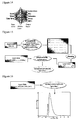
- the transform ⁇ present in the block scheme of figure 15, is obtained by throwing an evolutive algorithm which minimises an error function, relating to the fitting of the experimental HRR on the considered Wiebe function set.
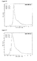
- Figure 17 indicates the set of two Wiebe functions used for the fitting of the mean HRR relating to our test case. The first of the two functions approximates the "Pilot” step of the HRR whereas the second one approximates the "Main” step.
- the number s of coefficients (c k 1 , ..., c k 2 , c k s ) is equal to 10; i.e. for each Wiebe function the parameters that the evolutive algorithm must determine are 5: a efficiency parameter of the combustion, m chamber form factor, ⁇ i and ⁇ f start and end angles of the combustion and finally m c combustible mass. These parameters relate only to the combustion process part which is approximated by the examined Wiebe function.
- Wn indicates the number of the chosen Wiebe functions whereon the HRR signal is to be decomposed.
- An evolutive algorithm e.g. the ES - (1 + 1), converges when all the P strings, constituting the population individuals, for a certain number of iterations t min do not remarkably improve the fitness thereof, i.e. when I ⁇ f t,t +1 j / f t j
- ⁇ Er conv j 1, 2, ..P
- the aim is that of singling out "optimal" coefficient strings(c kopt1 , ..., c kopts ), in correspondence wherewith similar variations occur between the input data and the output data (output data mean the coefficient strings).
- the "grey-box" model effective to simulate the trend of the mean HRR for a diesel engine, is, in practice, a neural network MLP.
- This network trains on a set of previously taken experimental input data and of corresponding output data (c kopt1 ,..., c koptS ), in order to effectively establish the coefficient string (c k 1 , ..., c k s ) associated with any input datum.
- the points at issue are the pairs of input data and output data whereon the network is trained.
- the cited reconstruction problem is generally a non well-posed problem.
- the presence of noise and/or imprecision in the acquirement of the experimental data increases the probability that one of the three conditions characterising a well-posed problem is not satisfied.
- ⁇ x (..,..) indicates the distance between the two arguments thereof in the reference vectorial space (this latter is singled out by the subscript of the function ⁇ x ). If only one of the three conditions is not satisfied then the problem is called non well-posed; this means that, of all the sample of available data for the training of the neural network, only a few are effectively used in the reconstruction of the map f.
- the last step of the set-up process of the model coincides with the training of a neural network MLP on the set of Ntot input data and of the corresponding target data. These latter are the coefficient strings ( C k / opt 1,..., C k / opts ) selected in the previous clustering step.
- the topology of the used MLP network has not been chosen in an "empirical" way.
- the final result is a network able to establish, from a given fuel multiple injection strategy and a given engine point, the coefficient string which, in the Wiebe functional set, reconstructs the mean HRR signal.
- the calibration procedure of the characteristic parameters of the Wiebe functions which describe the trend of the heat dissipation speed (HRR) in combustion processes in diesel engines with common rail injection system, consists in comprising the dynamics of the inner cylinder processes for a predetermined geometry of the combustion chamber.
- Each diesel engine differs from another not only for the main geometric characteristics, i.e. run, bore and compression ratio, but also for the intake and exhaust conduit geometry and for the bowl geometry.
- control parameters of the above described common rail injection system are: the injection pressure and the control strategy of the injectors (SOI, duration and rest between the control currents of the injectors).
- SOI injection pressure
- duration and rest between the control currents of the injectors A first typology of experimental tests is aimed at measuring the amount of fuel injected by each injection at a predetermined pressure inside the rail and for a combination of the duration and of the rest between the injections.
- the second typology of the tests relates to the dynamics of the combustion processes. These are realised in an engine testing room, through measures of the pressure in the cylinder under predetermined operation conditions.
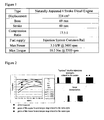
- the engine being the subject of this study is installed on an engine testing bank and it is connected with a dynamometric brake, i.e. with a device able to absorb the power generated by the propeller and to measure the torque delivered therefrom.
- Measures of the pressure in chamber effective to characterise the combustion processes when the control parameters and the speed vary are carried out inside the operation field of the engine.
- the characterisation of the processes starting from the measure of the pressure in chamber first consists in the analysis and in the treatment of the acquired data and then in the calculation of the HRR through the formula 8, 9, 10.
- the number of data to acquire in the testing room depends on the desired accuracy for the model in the establishment of the combustion process and thus of the pressure in chamber of the engine.
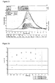
- Figures 23, 24 and 25 report an example of the pressure in the cylinder for a rotation speed of 2200rpm and for different control strategies of the two injection injector which differ for the shift of the first injection SOI and for the interval between the two ("dwell time").
- a summarising diagram has also been reported of the measured driving shaft torques, see figure 26.
Landscapes
- Engineering & Computer Science (AREA)
- Chemical & Material Sciences (AREA)
- Combustion & Propulsion (AREA)
- Mechanical Engineering (AREA)
- General Engineering & Computer Science (AREA)
- Artificial Intelligence (AREA)
- Evolutionary Computation (AREA)
- Electrical Control Of Air Or Fuel Supplied To Internal-Combustion Engine (AREA)
- Combined Controls Of Internal Combustion Engines (AREA)
Priority Applications (4)
| Application Number | Priority Date | Filing Date | Title |
|---|---|---|---|
| DE602004015088T DE602004015088D1 (de) | 2004-05-31 | 2004-05-31 | Verfahren zum Berechnen der Hitzefreigabe (HRR) in einer Diesel Brennkraftmaschine mit Common-Rail |
| EP04425398A EP1607604B1 (fr) | 2004-05-31 | 2004-05-31 | Procédé informatique de calcul du taux de dégagement de chaleur (HRR) dans un moteur à combustion interne avec un système d'injection à rampe commune |
| US11/142,914 US7120533B2 (en) | 2004-05-31 | 2005-05-31 | Soft-computing method for establishing the heat dissipation law in a diesel common rail engine |
| US11/527,012 US7369935B2 (en) | 2004-05-31 | 2006-09-25 | Soft-computing method for establishing the heat dissipation law in a diesel common rail engine |
Applications Claiming Priority (1)
| Application Number | Priority Date | Filing Date | Title |
|---|---|---|---|
| EP04425398A EP1607604B1 (fr) | 2004-05-31 | 2004-05-31 | Procédé informatique de calcul du taux de dégagement de chaleur (HRR) dans un moteur à combustion interne avec un système d'injection à rampe commune |
Publications (2)
| Publication Number | Publication Date |
|---|---|
| EP1607604A1 true EP1607604A1 (fr) | 2005-12-21 |
| EP1607604B1 EP1607604B1 (fr) | 2008-07-16 |
Family
ID=34932530
Family Applications (1)
| Application Number | Title | Priority Date | Filing Date |
|---|---|---|---|
| EP04425398A Expired - Lifetime EP1607604B1 (fr) | 2004-05-31 | 2004-05-31 | Procédé informatique de calcul du taux de dégagement de chaleur (HRR) dans un moteur à combustion interne avec un système d'injection à rampe commune |
Country Status (3)
| Country | Link |
|---|---|
| US (2) | US7120533B2 (fr) |
| EP (1) | EP1607604B1 (fr) |
| DE (1) | DE602004015088D1 (fr) |
Cited By (3)
| Publication number | Priority date | Publication date | Assignee | Title |
|---|---|---|---|---|
| DE102006001271A1 (de) * | 2006-01-10 | 2007-07-12 | Siemens Ag | System zur Bestimmung des Verbrennungsbeginns bei einer Brennkraftmaschine |
| CN101761407B (zh) * | 2010-01-29 | 2013-01-16 | 山东申普交通科技有限公司 | 基于灰色系统预测理论的内燃机喷油量的主动控制方法 |
| DE102007021592B4 (de) * | 2006-05-09 | 2014-07-10 | GM Global Technology Operations LLC (n. d. Ges. d. Staates Delaware) | Verfahren für die erstellung eines maschinenkennfelds und -modells während eines entwicklungsprozesses einer brennkraftmaschine |
Families Citing this family (12)
| Publication number | Priority date | Publication date | Assignee | Title |
|---|---|---|---|---|
| EP1607604B1 (fr) * | 2004-05-31 | 2008-07-16 | STMicroelectronics S.r.l. | Procédé informatique de calcul du taux de dégagement de chaleur (HRR) dans un moteur à combustion interne avec un système d'injection à rampe commune |
| US7953279B2 (en) | 2007-06-28 | 2011-05-31 | Microsoft Corporation | Combining online and offline recognizers in a handwriting recognition system |
| US8301356B2 (en) * | 2008-10-06 | 2012-10-30 | GM Global Technology Operations LLC | Engine out NOx virtual sensor using cylinder pressure sensor |
| US8538659B2 (en) * | 2009-10-08 | 2013-09-17 | GM Global Technology Operations LLC | Method and apparatus for operating an engine using an equivalence ratio compensation factor |
| DE102011002678A1 (de) * | 2011-01-14 | 2012-07-19 | Robert Bosch Gmbh | Verfahren und Vorrichtung zur automatischen Erzeugung von Kennfeld-Kennlinien-Strukturen für eine Regelung und/oder Steuerung eines Systems, insbesondere eines Verbrennungsmotors |
| US9279406B2 (en) | 2012-06-22 | 2016-03-08 | Illinois Tool Works, Inc. | System and method for analyzing carbon build up in an engine |
| JP6540424B2 (ja) | 2015-09-24 | 2019-07-10 | 富士通株式会社 | 推定装置、推定方法、推定プログラム、エンジンおよび移動装置 |
| JP6540824B2 (ja) * | 2015-11-24 | 2019-07-10 | 富士通株式会社 | Wiebe関数パラメータ同定方法及びWiebe関数パラメータ同定装置 |
| US10196997B2 (en) * | 2016-12-22 | 2019-02-05 | GM Global Technology Operations LLC | Engine control system including feed-forward neural network controller |
| CN109214609A (zh) * | 2018-11-15 | 2019-01-15 | 辽宁大学 | 一种基于分数阶离散灰色模型的年用电量预测方法 |
| CN112784507B (zh) * | 2021-02-02 | 2024-04-09 | 一汽解放汽车有限公司 | 模拟高压共轨泵内燃油流动的全三维耦合模型建立方法 |
| CN118797354B (zh) * | 2024-09-12 | 2025-02-11 | 青岛科技大学 | 一种油酸甲酯环氧化反应效率提高的参数确定方法 |
Citations (1)
| Publication number | Priority date | Publication date | Assignee | Title |
|---|---|---|---|---|
| EP1363005A2 (fr) * | 2002-05-15 | 2003-11-19 | Caterpillar Inc. | Dispositif de commande d'un moteur utilisant un réseau de neurone en cascade |
Family Cites Families (8)
| Publication number | Priority date | Publication date | Assignee | Title |
|---|---|---|---|---|
| US6089077A (en) * | 1997-06-26 | 2000-07-18 | Cooper Automotive Products, Inc. | Mass fraction burned and pressure estimation through spark plug ion sensing |
| JPH11343916A (ja) * | 1998-06-02 | 1999-12-14 | Yamaha Motor Co Ltd | エンジン制御におけるデータ推定方法 |
| JP2000321176A (ja) * | 1999-05-17 | 2000-11-24 | Mitsui Eng & Shipbuild Co Ltd | 異常検知方法および装置 |
| JP3503694B2 (ja) * | 2000-03-28 | 2004-03-08 | 日本電気株式会社 | 目標識別装置および目標識別方法 |
| EP1477651A1 (fr) * | 2003-05-12 | 2004-11-17 | STMicroelectronics S.r.l. | Méthode et procédé pour déterminer la pression à l'intérieur de la chambre de combustion d'un moteur à explosion, en particulier d'un moteur à allumage spontané, et pour commander l'injection de carburant dans le moteur |
| MY144690A (en) * | 2003-06-20 | 2011-10-31 | Scuderi Group Llc | Split-cycle four-stroke engine |
| US7031828B1 (en) * | 2003-08-28 | 2006-04-18 | John M. Thompson | Engine misfire detection system |
| EP1607604B1 (fr) * | 2004-05-31 | 2008-07-16 | STMicroelectronics S.r.l. | Procédé informatique de calcul du taux de dégagement de chaleur (HRR) dans un moteur à combustion interne avec un système d'injection à rampe commune |
-
2004
- 2004-05-31 EP EP04425398A patent/EP1607604B1/fr not_active Expired - Lifetime
- 2004-05-31 DE DE602004015088T patent/DE602004015088D1/de not_active Expired - Lifetime
-
2005
- 2005-05-31 US US11/142,914 patent/US7120533B2/en not_active Expired - Lifetime
-
2006
- 2006-09-25 US US11/527,012 patent/US7369935B2/en not_active Expired - Lifetime
Patent Citations (1)
| Publication number | Priority date | Publication date | Assignee | Title |
|---|---|---|---|---|
| EP1363005A2 (fr) * | 2002-05-15 | 2003-11-19 | Caterpillar Inc. | Dispositif de commande d'un moteur utilisant un réseau de neurone en cascade |
Non-Patent Citations (3)
| Title |
|---|
| ARSIE I ET AL: "A SINGLE-ZONE MODEL FOR COMBUSTION AND NOX SIMULATION IN COMMON-RAIL MULTI-JET DIESEL ENGINES", SAE TECHNICAL PAPER SERIES, SOCIETY OF AUTOMOTIVE ENGINEERS, WARRENDALE, PA, US, 2003, pages 8, XP001155468, ISSN: 0148-7191 * |
| HARVEY P S ET AL: "AN ANALYSIS OF THE INFLUENCE OF SWIRL ON COMBUSTION IN DL DIESEL ENGINES BY COMPUTER SIMULATION", SAE TECHNICAL PAPER SERIES, SOCIETY OF AUTOMOTIVE ENGINEERS, WARRENDALE, PA, US, 1 January 1982 (1982-01-01), pages 247 - 258, XP008018022, ISSN: 0148-7191 * |
| HITOSHI SHIRAISHI ET AL: "CMAC NEURAL NETWORK CONTROLLER FOR FUEL-INJECTION SYSTEMS", IEEE TRANSACTIONS ON CONTROL SYSTEMS TECHNOLOGY, IEEE INC. NEW YORK, US, vol. 3, no. 1, 1 March 1995 (1995-03-01), pages 32 - 38, XP000508608, ISSN: 1063-6536 * |
Cited By (5)
| Publication number | Priority date | Publication date | Assignee | Title |
|---|---|---|---|---|
| DE102006001271A1 (de) * | 2006-01-10 | 2007-07-12 | Siemens Ag | System zur Bestimmung des Verbrennungsbeginns bei einer Brennkraftmaschine |
| DE102006001271B4 (de) * | 2006-01-10 | 2007-12-27 | Siemens Ag | System zur Bestimmung des Verbrennungsbeginns bei einer Brennkraftmaschine |
| US7438049B2 (en) | 2006-01-10 | 2008-10-21 | Siemens Aktiengesellschaft | System for determining the start of combustion in an internal combustion engine |
| DE102007021592B4 (de) * | 2006-05-09 | 2014-07-10 | GM Global Technology Operations LLC (n. d. Ges. d. Staates Delaware) | Verfahren für die erstellung eines maschinenkennfelds und -modells während eines entwicklungsprozesses einer brennkraftmaschine |
| CN101761407B (zh) * | 2010-01-29 | 2013-01-16 | 山东申普交通科技有限公司 | 基于灰色系统预测理论的内燃机喷油量的主动控制方法 |
Also Published As
| Publication number | Publication date |
|---|---|
| US20070021902A1 (en) | 2007-01-25 |
| US7120533B2 (en) | 2006-10-10 |
| DE602004015088D1 (de) | 2008-08-28 |
| EP1607604B1 (fr) | 2008-07-16 |
| US20050273244A1 (en) | 2005-12-08 |
| US7369935B2 (en) | 2008-05-06 |
Similar Documents
| Publication | Publication Date | Title |
|---|---|---|
| EP1607604B1 (fr) | Procédé informatique de calcul du taux de dégagement de chaleur (HRR) dans un moteur à combustion interne avec un système d'injection à rampe commune | |
| Fu et al. | Application of artificial neural network to forecast engine performance and emissions of a spark ignition engine | |
| Parlak et al. | Application of artificial neural network to predict specific fuel consumption and exhaust temperature for a diesel engine | |
| Atkinson et al. | Dynamic model-based calibration optimization: An introduction and application to diesel engines | |
| CN101713321B (zh) | 使用气缸压力传感器的发动机排出nox的虚拟传感器 | |
| Shiao et al. | Cylinder pressure and combustion heat release estimation for SI engine diagnostics using nonlinear sliding observers | |
| US11078857B2 (en) | Calculation of exhaust emissions of a motor vehicle | |
| Sun et al. | Design and control of automotive propulsion systems | |
| Isermann et al. | Design of computer controlled combustion engines | |
| Martínez-Morales et al. | Modeling and multi-objective optimization of a gasoline engine using neural networks and evolutionary algorithms | |
| Mozaffari et al. | A nonlinear model predictive controller with multiagent online optimizer for automotive cold-start hydrocarbon emission reduction | |
| Yum et al. | An experimental investigation of the effects of cyclic transient loads on a turbocharged diesel engine | |
| He et al. | Modeling of a turbocharged di diesel engine using artificial neural networks | |
| Fischer | Transient NOx estimation using artificial neural networks | |
| Malikopoulos et al. | Optimal engine calibration for individual driving styles | |
| Thiel et al. | Experimental optimization of a heavy-duty diesel engine using automated genetic algorithms | |
| Martínez-Morales et al. | Modeling of internal combustion engine emissions by LOLIMOT algorithm | |
| Brace | Prediction of diesel engine exhaust emissions using artificial neural networks | |
| Omran et al. | Neural networks for real‐time nonlinear control of a variable geometry turbocharged diesel engine | |
| Shin et al. | Application of physical model test-based long short-term memory algorithm as a virtual sensor for nitrogen oxide prediction in diesel engines | |
| Bruce et al. | Prediction of emissions from a turbocharged passenger car diesel engine using a neural network | |
| Balawender et al. | Modeling of unburned hydrocarbon emission in a DI diesel engine using neural networks | |
| Saad et al. | Combustion modeling of a direct injection diesel engine using double Wiebe functions: application to HiL real-time simulations | |
| Dimitrakopoulos | Real-time Virtual Sensor for NOx emisions and stoichiometric air-fuel ratio λ of a Marine Diesel Engine Using Neural Networks | |
| Zeng et al. | The development of a computer-based teaching tool for internal combustion engine courses |
Legal Events
| Date | Code | Title | Description |
|---|---|---|---|
| PUAI | Public reference made under article 153(3) epc to a published international application that has entered the european phase |
Free format text: ORIGINAL CODE: 0009012 |
|
| AK | Designated contracting states |
Kind code of ref document: A1 Designated state(s): AT BE BG CH CY CZ DE DK EE ES FI FR GB GR HU IE IT LI LU MC NL PL PT RO SE SI SK TR |
|
| AX | Request for extension of the european patent |
Extension state: AL HR LT LV MK |
|
| 17P | Request for examination filed |
Effective date: 20060621 |
|
| AKX | Designation fees paid |
Designated state(s): DE FR GB IT |
|
| 17Q | First examination report despatched |
Effective date: 20061024 |
|
| 17Q | First examination report despatched |
Effective date: 20061024 |
|
| GRAP | Despatch of communication of intention to grant a patent |
Free format text: ORIGINAL CODE: EPIDOSNIGR1 |
|
| GRAS | Grant fee paid |
Free format text: ORIGINAL CODE: EPIDOSNIGR3 |
|
| GRAA | (expected) grant |
Free format text: ORIGINAL CODE: 0009210 |
|
| AK | Designated contracting states |
Kind code of ref document: B1 Designated state(s): DE FR GB IT |
|
| REG | Reference to a national code |
Ref country code: GB Ref legal event code: FG4D |
|
| REF | Corresponds to: |
Ref document number: 602004015088 Country of ref document: DE Date of ref document: 20080828 Kind code of ref document: P |
|
| PLBE | No opposition filed within time limit |
Free format text: ORIGINAL CODE: 0009261 |
|
| STAA | Information on the status of an ep patent application or granted ep patent |
Free format text: STATUS: NO OPPOSITION FILED WITHIN TIME LIMIT |
|
| 26N | No opposition filed |
Effective date: 20090417 |
|
| PG25 | Lapsed in a contracting state [announced via postgrant information from national office to epo] |
Ref country code: IT Free format text: LAPSE BECAUSE OF FAILURE TO SUBMIT A TRANSLATION OF THE DESCRIPTION OR TO PAY THE FEE WITHIN THE PRESCRIBED TIME-LIMIT Effective date: 20080716 |
|
| GBPC | Gb: european patent ceased through non-payment of renewal fee |
Effective date: 20090531 |
|
| REG | Reference to a national code |
Ref country code: FR Ref legal event code: ST Effective date: 20100129 |
|
| PG25 | Lapsed in a contracting state [announced via postgrant information from national office to epo] |
Ref country code: FR Free format text: LAPSE BECAUSE OF NON-PAYMENT OF DUE FEES Effective date: 20090602 |
|
| PG25 | Lapsed in a contracting state [announced via postgrant information from national office to epo] |
Ref country code: GB Free format text: LAPSE BECAUSE OF NON-PAYMENT OF DUE FEES Effective date: 20090531 |
|
| PGFP | Annual fee paid to national office [announced via postgrant information from national office to epo] |
Ref country code: DE Payment date: 20150422 Year of fee payment: 12 |
|
| REG | Reference to a national code |
Ref country code: DE Ref legal event code: R119 Ref document number: 602004015088 Country of ref document: DE |
|
| PG25 | Lapsed in a contracting state [announced via postgrant information from national office to epo] |
Ref country code: DE Free format text: LAPSE BECAUSE OF NON-PAYMENT OF DUE FEES Effective date: 20161201 |