EP1607655B1 - Dispositif pour absorber l'énergie d'un choc - Google Patents
Dispositif pour absorber l'énergie d'un choc Download PDFInfo
- Publication number
- EP1607655B1 EP1607655B1 EP05076706A EP05076706A EP1607655B1 EP 1607655 B1 EP1607655 B1 EP 1607655B1 EP 05076706 A EP05076706 A EP 05076706A EP 05076706 A EP05076706 A EP 05076706A EP 1607655 B1 EP1607655 B1 EP 1607655B1
- Authority
- EP
- European Patent Office
- Prior art keywords
- composite material
- fiber reinforced
- reinforced composite
- hollow tubes
- energy absorber
- Prior art date
- Legal status (The legal status is an assumption and is not a legal conclusion. Google has not performed a legal analysis and makes no representation as to the accuracy of the status listed.)
- Expired - Lifetime
Links
Images







Classifications
-
- F—MECHANICAL ENGINEERING; LIGHTING; HEATING; WEAPONS; BLASTING
- F16—ENGINEERING ELEMENTS AND UNITS; GENERAL MEASURES FOR PRODUCING AND MAINTAINING EFFECTIVE FUNCTIONING OF MACHINES OR INSTALLATIONS; THERMAL INSULATION IN GENERAL
- F16F—SPRINGS; SHOCK-ABSORBERS; MEANS FOR DAMPING VIBRATION
- F16F7/00—Vibration-dampers; Shock-absorbers
- F16F7/12—Vibration-dampers; Shock-absorbers using plastic deformation of members
- F16F7/124—Vibration-dampers; Shock-absorbers using plastic deformation of members characterised by their special construction from fibre-reinforced plastics
-
- B—PERFORMING OPERATIONS; TRANSPORTING
- B64—AIRCRAFT; AVIATION; COSMONAUTICS
- B64C—AEROPLANES; HELICOPTERS
- B64C1/00—Fuselages; Constructional features common to fuselages, wings, stabilising surfaces or the like
- B64C1/06—Frames; Stringers; Longerons ; Fuselage sections
- B64C1/061—Frames
- B64C1/062—Frames specially adapted to absorb crash loads
-
- F—MECHANICAL ENGINEERING; LIGHTING; HEATING; WEAPONS; BLASTING
- F16—ENGINEERING ELEMENTS AND UNITS; GENERAL MEASURES FOR PRODUCING AND MAINTAINING EFFECTIVE FUNCTIONING OF MACHINES OR INSTALLATIONS; THERMAL INSULATION IN GENERAL
- F16F—SPRINGS; SHOCK-ABSORBERS; MEANS FOR DAMPING VIBRATION
- F16F7/00—Vibration-dampers; Shock-absorbers
- F16F7/12—Vibration-dampers; Shock-absorbers using plastic deformation of members
- F16F7/121—Vibration-dampers; Shock-absorbers using plastic deformation of members the members having a cellular, e.g. honeycomb, structure
-
- B—PERFORMING OPERATIONS; TRANSPORTING
- B64—AIRCRAFT; AVIATION; COSMONAUTICS
- B64C—AEROPLANES; HELICOPTERS
- B64C27/00—Rotorcraft; Rotors peculiar thereto
- B64C27/04—Helicopters
-
- F—MECHANICAL ENGINEERING; LIGHTING; HEATING; WEAPONS; BLASTING
- F16—ENGINEERING ELEMENTS AND UNITS; GENERAL MEASURES FOR PRODUCING AND MAINTAINING EFFECTIVE FUNCTIONING OF MACHINES OR INSTALLATIONS; THERMAL INSULATION IN GENERAL
- F16F—SPRINGS; SHOCK-ABSORBERS; MEANS FOR DAMPING VIBRATION
- F16F2224/00—Materials; Material properties
- F16F2224/02—Materials; Material properties solids
- F16F2224/0241—Fibre-reinforced plastics [FRP]
Definitions
- the present invention relates to an energy absorber used for an impact resistant structure for a helicopter.
- a helicopter is often operated in visual flight rule, or between mountains, or at a low altitude, because of its operating characteristics. Then, there is always a risk of accident due to contact with an obstacle. Therefore, an impact resistance is strongly required in a helicopter in order to keep survivability of crew members in the crash situations.
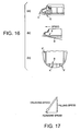
- the basic principle for the impact resistant structure of a helicopter is to adopt a continuous strong keel K for a nose H easily crushed and a bottom G easily crushed which are shown in Fig. 16(a) to prevent a floor D from structural failure on crash landing as shown in Fig. 16(b), to adopt a strong outer skin P as shown in Fig. 16(c), to adopt a strong beam B on the keel K, and to adopt a continuous strong frame F.
- an impact resistant fuselage structure having impact absorption capacity is required for the typical crush environment shown in Fig. 17 in a shape fitting to the actual helicopter fuselage structure.
- the floor structure of a helicopter is designed according to a normal operational flight load and a landing load on the ground.
- general impact absorption to an unexpected crash impact like crushing shown in Fig. 17 is not taken into account.
- Examples of impact resistance absorption members used in the impact resistant structure of a helicopter and the impact resistant structure for general industrial purpose are disclosed in Japanese Patent Laid-Open Publications No.2002-286066 , No.2002-36413 , No.2002-153169 , No.2002-192432 , and USP No.5746537 , such as an example using axial compression energy absorption of a light weight fiber reinforced composite material tube, and an example that a foaming material is filled up in all sections for energy absorption improvement.
- the aspect ratio (energy absorber height/section width) of whole the energy absorber becomes long and slim, and the energy absorber becomes weak for bending and eccentric compression, so a desired axial compression energy absorption property cannot be achieved.
- the section of the tube is made compact, and is made into a bundling shape, when the number of tubes is optionally adjusted, the number of intersections between stiff walls increases as the number of tubes increases, so that as shown in Fig. 21, the initial load peak level harmful for the impact absorption property increases.
- US-A- 4593870 discloses an energy absorbing composite aircraft structure.
- the energy absorber includes a thin panel formed of composite materials for reacting compression forces in the plane of the panel between two opposed edges thereof.
- the panel is constructed to resist overall bending failure when force is applied to the opposite edges.
- the energy absorber further includes force receiving structure for receiving forces directly to one of the edges and for receiving forces to the opposite edge of the panel to initiate local folding parallel to the other edge for progressing crushing and local folding of the panel.
- an object of the present invention is to provide an energy absorber to be used in an impact resistant structure of a helicopter, i.e., for a helicopter of which landing gear such as retracted one may not be effectively functioned in crash situation, to provide a fuselage structure having impact absorption capacity against the actual crash environment while providing in a shape fitting to the actual helicopter fuselage structure.
- the object of the present invention is to provide a light weight energy high performance absorber in which the harmful initial load peak level is reduced, and in which the energy absorption property due to axial compression failure is improved, also which is able to apply not only to the impact resistant structure of a helicopter but also to the impact resistant structure for general industrial purpose, and which have a desired impact absorption capacity in a shape fitting to the actual helicopter fuselage structure, furthermore in which the effective stroke is increased.
- an energy absorber comprising:
- the hollow tubes of fiber reinforced composite material and the outer layer of fiber reinforced composite material are arranged such that the number of intersecting walls of the hollow tubes or the outer layer is less than four surfaces.
- the hollow tubes of fiber reinforced composite material and the outer layer of fiber reinforced composite material for bundling the hollow tubes are integrally formed.
- a foaming material is inserted into a properly selected space from between the hollow tubes of fiber reinforced composite material, between the hollow tubes of fiber reinforced composite material and the outer layer of fiber reinforced composite material, and insides of the hollow tubes of fiber reinforced composite material.
- the hollow tubes of fiber reinforced composite material are provided with a sectional space for storing destroyed small pieces sequentially generated by progressive crushing.
- a sectional shape of each of the hollow tubes of fiber reinforced composite material is circular, elliptic, square, triangular, hexagonal, or octagonal.
- the hollow tubes of fiber reinforced composite material are arranged in a row or in plural rows and are bundled circularly, elliptically, rectangularly, or squarely by the outer layer of fiber reinforced composite material.
- the hollow tubes of fiber reinforced composite material, the foaming material, and the outer layer of fiber reinforced composite material are integrally formed.
- the gray parts shown in Fig. 1 are energy absorbers 1 in bundled-tubes state.
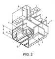
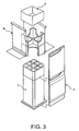
- the energy absorbers 1 are arranged under the floor in accordance with the ground reaction force distribution at the time of crash situation on the general ground surface shown in Fig. 17 and are directly connected to a frame 2 as shown in Figs. 2 and 3.
- the energy absorbers 1 in the bundled-tubes state may be directly connected to the frame 2 almost directly under the side wall of the frame 2 where the impact load is concentrated at the time of crash situation shown in Fig. 17.
- numeral 3 indicates an under-floor outer skin or web and on the under-floor outer skin or web 3, many curved panels 4 are arranged integrally and in parallel with each other almost in the longitudinal direction of the helicopter.
- the curved panels 4 operate as a keel beam during the normal operational use as shown in Figs. 2 and 3, receive the horizontal load due to the forward speed at the time of crash situation shown in Fig. 17, and are crushed in a pantograph shape by the vertical load.
- a truss frame 5 is installed in an almost X shape as shown in Fig. 2.
- the truss frame 5 holds the curved panels during the normal operational use.
- the truss frame 5 does not prevent the curved panels 4 from deformation at the time of crushing.
- a floor beam 6 is arranged on the curved panels 4.
- the floor beam 6 is connected to the frame 2, to which the energy absorbers 1 are directly connected, as shown in Fig. 2, thereby, a frame-floor beam structure 7 is formed.
- the energy absorbers 1 in the bundled-tubes state are arranged under the floor in accordance with the ground reaction force distribution at the time of crash situation on the general ground surface and are directly connected to the frame 2. Thereby, even if the under-floor crush load is concentrated on the outer wall, the energy of crash is absorbed stably by the energy absorbers 1 in the bundled-tubes state which is excellent in energy absorption per unit weight.
- the truss frame 5 is installed between the curved panels 4, so that the truss frame 5, during the normal operational use, functions as a frame member for holding the curved panels 4, and at the time of crash situation, the curved panels 4 are surely crushed in a pantograph shape without preventing deformation, and the crash impact absorption capacity of sub-floor is improved.
- a gate-shape cabin structure 8 connected to the frame 2 at both side ends as shown in Fig. 4 can be formed above the frame-floor beam structure 7.
- the cabin structure 8 is supported by the frame-floor beam structure 7, and at the time of crash situation, the frame-floor beam structure 7 is prevented from destruction because the impact is absorbed by the energy absorbers 1 in the bundled-tubes state and the curved panels 4.
- the cabin structure 8 is also prevented from destruction, and a crew member's survivable volume 9 inside the cabin structure 8 is maintained, and the survivability of crew members is improved.
- the cabin structure 8 is a crew member's protective shell structure for preventing heavy equipments, e.g., a transmission, engine, etc., on the ceiling from falling or intrusion into the cabin at the time of crash situation and thereby the crew member's survivable volume is reserved.
- the energy absorbers 1 of the present embodiment used in the aforementioned impact resistant structure of a helicopter will be explained by referring to the drawings.
- the energy absorbers 1 it is desirable to bundle a plurality of hollow tubes of fiber reinforced composite material, reduce the number of intersecting walls of the hollow tubes of fiber reinforced composite material, and integrally form them.
- one unlimited example of the energy absorbers 1 is that as shown in Fig. 5, a plurality of independent hollow tubes of fiber reinforced composite material 10 having a small opening section are bundled by an outer layer made of fiber reinforced composite material 11, thus the walls of the hollow tubes of fiber reinforced composite material 10 which are light weight and excellent in energy absorption are stabilized from local buckling.
- the hollow tubes of fiber reinforced composite material 10 and the outer layer made of fiber reinforced composite material 11 for bundling them are arranged such that a number of intersecting walls of the hollow tubes or outer layer is less than four surfaces. Thereby, the harmful initial load peak for crew member's survivability is suppressed more.
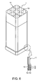
- the outer layer made of fiber reinforced composite material 11 as shown in Fig. 6, being formed in a plurality of layers in the thickness direction and between end portions 12 of the outer layer 11, a film-shaped layer material of low strength namely delamination films 13 are inserted, the harmful initial load peak for crew member's survivability is suppressed more.
- the energy absorbers 1 when the hollow tubes of fiber reinforced composite material 10 and the outer layer made of fiber reinforced composite material 11 for bundling them are integrally formed, energy of crush is preferably absorbed stably.
- Another example of the energy absorber 1 of the present embodiment is that as shown in Fig. 7, in the space between the hollow tubes of fiber reinforced composite material 10 and in the space between the hollow tubes of fiber reinforced composite material 10 and the outer layer made of fiber reinforced composite material 11 for bundling the tubes, a foaming material 14 is inserted. Thereby, the walls of the hollow tubes of fiber reinforced composite material 10 are more stabilized from local buckling.
- the foaming material 14 is inserted not only into the space between the hollow tubes of fiber reinforced composite material 10 and into the space between the hollow tubes of fiber reinforced composite material 10 and the outer layer made of fiber reinforced composite material 11 but also properly selected insides of the hollow tubes of fiber reinforced composite material 10.
- the hollow tubes of fiber reinforced composite material 10 are provided with a sectional space 15 for storing destroyed small pieces sequentially generated by progressive crushing, so that whole energy absorber is prevented from stiffening due to compacting of the destroyed small pieces.
- the energy absorbers 1 shown in Fig. 7 when the hollow tubes of fiber reinforced composite material 10, the foaming material 14, and the outer layer made of fiber reinforced composite material 11 for bundling the tubes are integrally formed, the strength for bending and eccentric compression can be obtained and energy of crash can be absorbed stably.
- each of the hollow tubes of fiber reinforced composite material 10 shown in the drawing is octagonal.
- it may be circular, elliptic, square, triangular, or hexagonal.
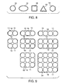
- the hollow tubes of fiber reinforced composite material 10 having, for example, an octagonal section may be arranged in a row, two rows, or three rows and bundled by the outer layer made of fiber reinforced composite material 11 rectangularly, squarely, circularly, or elliptically.
- the hollow tubes of fiber reinforced composite material 10 and the foaming material 14 may have the same sectional shape of circle, square, or octagon and may be bundled and arranged by the outer layer made of fiber reinforced composite material 11.
- the foaming material is inserted into the hollow tubes of fiber reinforced composite material 10 and has the same sectional shape as that of the hollow tubes of fiber reinforced composite material 10.
- the hollow tubes of fiber reinforced composite material 10 are composed of fibers and hollow tubes of fiber reinforced composite material of resin, and as fibers, fibers of glass, carbon, alamide, metal, or boron and conjugate fibers are selectively used, and as resin, thermoset resin and thermoplastics are selectively used.
- various materials such as polyethylene series, polyurethane series, polystyrene series, epoxy resin series, phenolic resin series, and polymethacrylic imide series are selectively used.
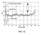
- the load-displacement characteristic test is carried out on an energy absorber of the conventional example and energy absorbers of Embodiments 1 and 2.
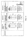
- the configuration of the energy absorbers of the conventional example and the configurations of the energy absorbers of Embodiments 1 and 2 are shown in Fig. 11 and the results of the load-displacement characteristic test of the energy absorbers are shown in the graphs in Fig. 12.
- the initial load peak harmful for the impact absorption property is extremely large, while in the energy absorber of Embodiment 1, the initial load peak is extremely suppressed and in the energy absorber of Embodiment 2, the initial load peak is eliminated.
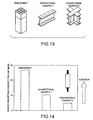
- the energy absorption property per unit mass of the energy absorber of the embodiment shown in Fig. 13 and the energy absorber of Conventional Examples 1 and 2 is measured.
- the graph in Fig. 14 shows that the energy absorber of the embodiment has an extremely high impact energy absorption property compared with the energy absorbers of Conventional Examples 1 and 2.
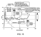
- the graphs in Fig. 15 show that in the energy absorber of the conventional example, the effective stroke is not used effectively due to unstable destruction, thus energy cannot be absorbed.
- the energy absorber of Embodiment 1 destroyed small pieces are cut into the foaming material, thus the member as a whole is prevented from stiffening due to compacting of the destroyed small pieces, and the effective stroke is sufficiently used.
- destroyed small pieces are stored in the sectional space, thus the member as a whole is prevented from stiffening due to compacting of the destroyed small pieces, and the effective stroke is sufficiently used.
- the impact resistant structure of a helicopter e.g. , a helicopter of which landing gear such as retracted one may not be effectively functioned, can produce an excellent effect that the fuselage structure can be provided with impact absorption capacity against the actual crash environment in a shape fitting to the actual helicopter fuselage structure.
- the energy absorber of the present invention can suppress the harmful initial load peak for crew member's survivability, improve the absorption property of compression crush energy, and increase the effective stroke, so that they can be applied not only to the impact resistant structure of a helicopter but also to the impact resistant structure for general industrial purpose and can provide a desired impact absorption capacity in a shape fitting to the actual helicopter fuselage structure.
Landscapes
- Engineering & Computer Science (AREA)
- General Engineering & Computer Science (AREA)
- Mechanical Engineering (AREA)
- Aviation & Aerospace Engineering (AREA)
- Vibration Dampers (AREA)
Claims (9)
- Dispositif absorbeur d'énergie comprenant :une pluralité de tubes creux indépendants (10) d'un matériau composite renforcé de fibres formé de manière solidaire en groupant lesdits tubes creux de matériau composite renforcé de fibres, dans lequel lesdits tubes creux de matériau composite renforcé de fibres sont agencés avec le nombre minimal de parois en intersection desdits tubes creux de matériau composite renforcé de fibres, dans lequel chacun desdits tubes creux (10) de matériau composite renforcé de fibres est formé en une pluralité de couches, et caractérisé par un film de déstratification (13) présentant une résistance mécanique inférieure à celle du matériau composite renforcé de fibres, inséré entre ladite pluralité de couches dudit matériau composite renforcé de fibres au niveau des portions d'extrémité des tubes.
- Dispositif absorbeur d'énergie selon la revendication 1, dans lequel lesdits tubes creux de matériau composite renforcé de fibres sont groupés par une couche externe (11) de matériau composite renforcé de fibres,
dans lequel lesdits tubes creux (10) de matériau composite renforcé de fibres et ladite couche externe de matériau composite renforcé de fibres sont agencés avec le nombre minimal de parois en intersection, et
dans lequel ladite couche externe de matériau composite renforcé de fibres est formée en une pluralité de couches, un film de déstratification (13) ayant une résistance mécanique inférieure à celle dudit matériau composite renforcé de fibres inséré entre lesdites couches de ladite couche externe au niveau de ses portions d'extrémité. - Dispositif absorbeur d'énergie selon la revendication 2, dans lequel lesdits tubes creux (10) de matériau composite renforcé de fibres et ladite couche externe (11) de matériau composite renforcé de fibres sont agencés de sorte que le nombre d'intersection desdites parois desdits tubes creux et/ou de ladite couche externe soit inférieur à quatre.
- Dispositif absorbeur d'énergie selon la revendication 1, 2 ou 3, dans lequel lesdits tubes creux (10) de matériau composite renforcé de fibres et de ladite couche externe (11) de matériau composite renforcé de fibres destinée à grouper lesdits tubes creux ont une forme globale solidaire.
- Dispositif absorbeur d'énergie selon l'une quelconque des revendications 1 à 4, dans lequel un matériau moussant (14) est inséré dans un espace entre lesdits tubes creux (10) de matériau composite renforcé de fibres, et/ou un espace entre lesdits tubes creux (10) de matériau composite renforcé de fibres et ladite couche externe (11) de matériau composite renforcé de fibres, et/ou un espace à l'intérieur desdits tubes creux de matériau composite renforcé de fibres.
- Dispositif absorbeur d'énergie selon l'une quelconque des revendications 1 à 5, dans lequel lesdits tubes creux (10) de matériau composite renforcé de fibres sont pourvus d'un espace interne destiné à stocker de petites pièces générées par un écrasement progressif dans le cas d'un choc.
- Dispositif absorbeur d'énergie selon l'une quelconque des revendications 1 à 6, dans lequel la forme en coupe transversale de chacun desdits tubes creux (10) de matériau composite renforcé de fibres est circulaire, elliptique, carrée, triangulaire, hexagonale ou octogonale.
- Dispositif absorbeur d'énergie selon la revendication 2, dans lequel lesdits tubes creux (10) de matériau composite renforcé de fibres sont agencés en une rangée ou en plusieurs rangées et sont groupés de manière circulaire, elliptique, rectangulaire ou carrée par ladite couche externe de matériau composite renforcé de fibres.
- Dispositif absorbeur d'énergie selon la revendication 5, dans lequel lesdits tubes creux (10) de matériau composite renforcé de fibres, ledit matériau moussant (14) et ladite couche externe (11) de matériau composite renforcé de fibres ont une forme globale solidaire.
Applications Claiming Priority (3)
| Application Number | Priority Date | Filing Date | Title |
|---|---|---|---|
| JP2002353075A JP3888630B2 (ja) | 2002-12-04 | 2002-12-04 | エネルギー吸収部材及びそれを用いるヘリコプタの耐衝撃構造 |
| JP2002353075 | 2002-12-04 | ||
| EP03257598A EP1426289B1 (fr) | 2002-12-04 | 2003-12-03 | Structure d'hélicoptère résistant à l'impact et absorbeur d'énergie utilisé à cette fin |
Related Parent Applications (1)
| Application Number | Title | Priority Date | Filing Date |
|---|---|---|---|
| EP03257598A Division EP1426289B1 (fr) | 2002-12-04 | 2003-12-03 | Structure d'hélicoptère résistant à l'impact et absorbeur d'énergie utilisé à cette fin |
Publications (2)
| Publication Number | Publication Date |
|---|---|
| EP1607655A1 EP1607655A1 (fr) | 2005-12-21 |
| EP1607655B1 true EP1607655B1 (fr) | 2007-10-24 |
Family
ID=32310731
Family Applications (2)
| Application Number | Title | Priority Date | Filing Date |
|---|---|---|---|
| EP05076706A Expired - Lifetime EP1607655B1 (fr) | 2002-12-04 | 2003-12-03 | Dispositif pour absorber l'énergie d'un choc |
| EP03257598A Expired - Lifetime EP1426289B1 (fr) | 2002-12-04 | 2003-12-03 | Structure d'hélicoptère résistant à l'impact et absorbeur d'énergie utilisé à cette fin |
Family Applications After (1)
| Application Number | Title | Priority Date | Filing Date |
|---|---|---|---|
| EP03257598A Expired - Lifetime EP1426289B1 (fr) | 2002-12-04 | 2003-12-03 | Structure d'hélicoptère résistant à l'impact et absorbeur d'énergie utilisé à cette fin |
Country Status (4)
| Country | Link |
|---|---|
| US (1) | US6959894B2 (fr) |
| EP (2) | EP1607655B1 (fr) |
| JP (1) | JP3888630B2 (fr) |
| DE (2) | DE60317110T2 (fr) |
Families Citing this family (63)
| Publication number | Priority date | Publication date | Assignee | Title |
|---|---|---|---|---|
| CN100398379C (zh) * | 2002-03-15 | 2008-07-02 | 本田技研工业株式会社 | 制造固结颗粒物的方法 |
| EP1593872A1 (fr) * | 2004-05-06 | 2005-11-09 | Grupo Antolin-Ingenieria, S.A. | Amortisseur de choc et son procédé de fabrication |
| JP4304122B2 (ja) * | 2004-05-25 | 2009-07-29 | 三菱電機株式会社 | 電気車制御装置 |
| EP1607272B1 (fr) * | 2004-06-16 | 2008-08-13 | Jacob Composite GmbH | Pièce de construction pour absorbtion d'énergie en cas de collision |
| JP4723942B2 (ja) * | 2004-09-28 | 2011-07-13 | アイシン精機株式会社 | 車両の衝撃吸収具及び車両の衝撃吸収構造 |
| FR2884801B1 (fr) | 2005-04-22 | 2008-11-14 | Eurocopter France | Atterrisseur auxillaire de nez, structure porteuse et aeronef a voilure tournante |
| JP4520367B2 (ja) * | 2005-06-07 | 2010-08-04 | 川崎重工業株式会社 | 航空機の耐衝撃構造 |
| WO2007029362A1 (fr) * | 2005-09-09 | 2007-03-15 | Toyoda Iron Works Co., Ltd | Organe d’absorption d’impact pour véhicule |
| EP1777155B1 (fr) * | 2005-10-21 | 2008-12-10 | Agusta S.p.A. | Sous-structure déformable pour le plancher d'un hélicoptère |
| FR2896770B1 (fr) * | 2006-01-27 | 2008-04-11 | Eurocopter France | Structure composite anti-crash a maintien lateral pour aeronef. |
| FR2896768B1 (fr) * | 2006-01-27 | 2009-10-09 | Eurocopter France | Structure composite anti-crash a flambage controle pour aeronef. |
| US8709584B2 (en) * | 2006-01-31 | 2014-04-29 | Sikorsky Aircraft Corporation | Composite aircraft floor system |
| US8869673B2 (en) | 2006-01-31 | 2014-10-28 | Sikorsky Aircraft Corporation | Structural panel with ballistic protection |
| US9097496B2 (en) | 2006-04-20 | 2015-08-04 | Sikorsky Aircraft Corporation | Lightweight projectile resistant armor system with surface enhancement |
| US7735779B2 (en) * | 2006-11-02 | 2010-06-15 | The Boeing Company | Optimized fuselage structure |
| US8376275B2 (en) * | 2006-12-08 | 2013-02-19 | The Boeing Company | Energy absorbing structure for aircraft |
| US8043458B2 (en) * | 2007-06-21 | 2011-10-25 | Sikorsky Aircraft Corporation | Method of forming panels using an in-situ tape placement process and panels formed therefrom |
| US7828246B2 (en) * | 2007-09-14 | 2010-11-09 | Spectrum Aeronautical, Llc | Wing with sectioned tubular members |
| US7867928B2 (en) * | 2007-12-14 | 2011-01-11 | Sikorsky Aircraft Corporation | Fluid resistant composite sandwich panel |
| US8336807B2 (en) * | 2008-01-09 | 2012-12-25 | Bernard Hanafin | Combined helicopter landing pad and clamshell enclosure |
| WO2009098971A1 (fr) * | 2008-02-04 | 2009-08-13 | Toyoda Gosei Co., Ltd. | Dispositif déformable |
| FR2932556B1 (fr) | 2008-06-12 | 2014-09-12 | Nexter Systems | Dispositif de protection de plancher pour une cabine de vehicule |
| US8539737B2 (en) | 2008-09-19 | 2013-09-24 | Ford Global Technologies, Llc | Twelve-cornered strengthening member |
| US8181422B2 (en) * | 2008-12-23 | 2012-05-22 | Spirit Aerosystems, Inc. | Energy-absorbing structural composite element |
| DE102009012472A1 (de) * | 2009-03-12 | 2010-09-16 | Comat Composite Materials Gmbh | Zug-Druckstange mit definiertem Lastversagen |
| US9163369B2 (en) | 2009-04-07 | 2015-10-20 | Valmount Highway Technology Limited | Energy absorption device |
| JP4918567B2 (ja) * | 2009-04-20 | 2012-04-18 | 三菱重工業株式会社 | 衝撃吸収構造体およびその製造方法 |
| JP5297288B2 (ja) | 2009-07-17 | 2013-09-25 | 三菱重工業株式会社 | 衝撃吸収構造体 |
| JP5407773B2 (ja) * | 2009-11-06 | 2014-02-05 | トヨタ自動車株式会社 | エネルギー吸収構造 |
| JP5129827B2 (ja) * | 2010-02-12 | 2013-01-30 | 三菱重工業株式会社 | 衝撃吸収構造体及び衝撃吸収構造体の製造方法、並びに、移動体 |
| DE102010003497B4 (de) | 2010-03-31 | 2018-04-05 | Benteler Sgl Gmbh & Co. Kg | Verfahren zur Herstellung eines Aufprallschutzelementes |
| DE102010014638B4 (de) * | 2010-04-12 | 2019-08-01 | Airbus Defence and Space GmbH | Luftfahrzeug mit einer integrierten energieaufnehmenden Verformungsstruktur und Luftfahrzeug mit einem derartigen Rumpf |
| JPWO2011132292A1 (ja) * | 2010-04-22 | 2013-07-18 | トヨタ自動車株式会社 | エネルギー吸収構造体 |
| FR2959479B1 (fr) * | 2010-04-30 | 2012-06-15 | Eads Europ Aeronautic Defence | Structure de fuselage d'aeronef comportant un dispositif absorbeur d'energie |
| US20120104793A1 (en) * | 2010-10-29 | 2012-05-03 | Aptera Motors, Inc. | Automotive vehicle composite body structure |
| JP5765612B2 (ja) * | 2011-02-16 | 2015-08-19 | いすゞ自動車株式会社 | 衝撃エネルギー吸収体の複合構造及び衝撃エネルギー吸収体 |
| EP2505490A1 (fr) * | 2011-03-28 | 2012-10-03 | Airbus Opérations SAS | Amortisseur de chocs |
| DE102012013881A1 (de) | 2012-07-12 | 2013-01-24 | Daimler Ag | Strukturbauteil für eine Kraftfahrzeug-Karosserie und Verfahren zu dessen Herstellung |
| EP2876042B1 (fr) * | 2013-11-20 | 2018-01-03 | AIRBUS HELICOPTERS DEUTSCHLAND GmbH | Cellule d'hélicoptère |
| EP2889212B1 (fr) | 2013-12-30 | 2016-01-06 | AIRBUS HELICOPTERS DEUTSCHLAND GmbH | Structure de sous-plancher avec une coque intégral pour un aéronef à voilure tournante |
| PL2905228T3 (pl) | 2014-02-06 | 2018-05-30 | Airbus Helicopters Deutschland GmbH | Płatowiec kadłubowy i zbiornik |
| US9637212B2 (en) * | 2014-04-10 | 2017-05-02 | The Boeing Company | Aircraft body mounted energy absorbing rub strip |
| EP3023669B1 (fr) * | 2014-11-20 | 2020-12-30 | Airbus (Sas) | Dispositif d'absorption d'énergie cinétique et aéronef comportant un tel dispositif |
| CN104890604B (zh) * | 2015-06-23 | 2017-07-04 | 湖南大学 | 一种多胞汽车缓冲吸能装置 |
| US10315698B2 (en) | 2015-06-24 | 2019-06-11 | Ford Global Technologies, Llc | Sixteen-cornered strengthening member for vehicles |
| US10393315B2 (en) | 2016-04-26 | 2019-08-27 | Ford Global Technologies, Llc | Cellular structures with twelve-cornered cells |
| US10704638B2 (en) | 2016-04-26 | 2020-07-07 | Ford Global Technologies, Llc | Cellular structures with twelve-cornered cells |
| US10422401B2 (en) * | 2016-07-06 | 2019-09-24 | Toyota Motor Engineering & Manufacturing North America, Inc. | Energy-absorbing structure for vehicle |
| US10473177B2 (en) | 2016-08-23 | 2019-11-12 | Ford Global Technologies, Llc | Cellular structures with sixteen-cornered cells |
| US10220881B2 (en) | 2016-08-26 | 2019-03-05 | Ford Global Technologies, Llc | Cellular structures with fourteen-cornered cells |
| US10300947B2 (en) * | 2016-08-30 | 2019-05-28 | Ford Global Technologies, Llc | Twenty-eight-cornered strengthening member for vehicles |
| US10279842B2 (en) | 2016-08-30 | 2019-05-07 | Ford Global Technologies, Llc | Twenty-eight-cornered strengthening member for vehicles |
| US10429006B2 (en) | 2016-10-12 | 2019-10-01 | Ford Global Technologies, Llc | Cellular structures with twelve-cornered cells |
| US11034315B2 (en) * | 2018-04-17 | 2021-06-15 | Tesla, Inc. | Advanced thin-walled structures for enhanced crash performance |
| US11292522B2 (en) | 2019-12-04 | 2022-04-05 | Ford Global Technologies, Llc | Splayed front horns for vehicle frames |
| US11873111B2 (en) * | 2021-01-07 | 2024-01-16 | Textron Innovations Inc. | Fuel cell protection system |
| CN113044198A (zh) * | 2021-03-09 | 2021-06-29 | 上海交通大学 | 一种飞机地板下可固接-铰接转换的碰撞吸能斜支柱 |
| CN114412959B (zh) * | 2022-03-04 | 2025-02-11 | 西南石油大学 | 一种空间全方位自锁的串联薄壁管吸能系统 |
| KR20240096158A (ko) * | 2022-12-19 | 2024-06-26 | 현대자동차주식회사 | 충돌 하중 분산구조 |
| FR3156751A1 (fr) | 2023-12-14 | 2025-06-20 | Airbus Operations (S.A.S.) | Dispositif d’absorption d’énergie par compression, aéronef comprenant au moins un tel dispositif |
| FR3156752A1 (fr) * | 2023-12-14 | 2025-06-20 | Airbus Operations (S.A.S.) | Aéronef comprenant au moins un dispositif démontable d’absorption d’énergie par compression |
| FR3159588B1 (fr) * | 2024-02-23 | 2026-04-17 | Airbus Operations Sas | Dispositif d’absorption d’énergie par compression comprenant des tubes d’absorption de forme étoilée, aéronef comportant au moins un tel dispositif |
| CN120171583B (zh) * | 2025-05-21 | 2025-08-19 | 太原理工大学 | 一种拉伸变形吸能防冲击缓冲装置 |
Family Cites Families (31)
| Publication number | Priority date | Publication date | Assignee | Title |
|---|---|---|---|---|
| US3552525A (en) * | 1969-02-12 | 1971-01-05 | Hexcel Corp | Energy absorber |
| US3682463A (en) * | 1969-08-16 | 1972-08-08 | Dornier System Gmbh | Progressively-acting shock absorber element |
| US3664463A (en) * | 1970-11-10 | 1972-05-23 | Martin Marietta Corp | Deployable shock absorber |
| FR2288648A1 (fr) * | 1974-03-05 | 1976-05-21 | Peugeot & Renault | Pare-chocs composite absorbeur d'energie |
| GB1531460A (en) * | 1975-04-17 | 1978-11-08 | Imp Metal Ind Kynoch Ltd | Energy absorber |
| US3997133A (en) * | 1975-07-30 | 1976-12-14 | Textron, Inc. | Crash attenuation landing gear |
| US4227593A (en) * | 1976-10-04 | 1980-10-14 | H. H. Robertson Company | Kinetic energy absorbing pad |
| US4084029A (en) * | 1977-07-25 | 1978-04-11 | The Boeing Company | Sine wave beam web and method of manufacture |
| US4336868A (en) * | 1978-05-10 | 1982-06-29 | Textron, Inc. | Composite fibrous tube energy absorber |
| US4352484A (en) * | 1980-09-05 | 1982-10-05 | Energy Absorption Systems, Inc. | Shear action and compression energy absorber |
| DE3049425C2 (de) * | 1980-12-30 | 1991-09-05 | Messerschmitt-Bölkow-Blohm GmbH, 8000 München | Aufprall-Schutz-Bauteil |
| DE3401189A1 (de) * | 1983-01-25 | 1984-07-26 | Westland PLC, Yeovil, Somerset | Verbund-hubschrauberrumpf |
| US4593870A (en) * | 1983-09-09 | 1986-06-10 | Bell Helicopter Textron Inc. | Energy absorbing composite aircraft structure |
| FR2632604B1 (fr) * | 1988-06-08 | 1991-07-12 | Aerospatiale | Cadre en materiau composite notamment pour fuselage d'aeronef, et son procede de fabrication |
| US5069318A (en) * | 1989-12-26 | 1991-12-03 | Mcdonnell Douglas Corporation | Self-stabilized stepped crashworthy stiffeners |
| JP2858181B2 (ja) | 1991-01-21 | 1999-02-17 | 横浜ゴム株式会社 | エネルギー吸収構造体 |
| DE4313592C2 (de) * | 1993-04-26 | 2000-02-17 | Daimler Chrysler Aerospace | Großraumflugzeug |
| US5451015A (en) * | 1993-05-18 | 1995-09-19 | Bell Helicopter Textron Inc. | Crashworthy composite aircraft structure with integral fuel tank |
| US5366181A (en) * | 1993-12-01 | 1994-11-22 | The United States Of America As Represented By The Administrator Of The National Aeronautics And Space Administration | Landing gear energy absorption system |
| DE4425829C1 (de) | 1994-07-21 | 1995-10-12 | Daimler Benz Aerospace Ag | Strukturelement im Sandwich-Form |
| US5547148A (en) * | 1994-11-18 | 1996-08-20 | United Technologies Corporation | Crashworthy landing gear |
| US5746537A (en) * | 1996-03-20 | 1998-05-05 | The United States Of America As Represented By The Administrator Of The National Aeronautics And Space Administration | Crash-energy absorbing composite structure and method of fabrication |
| US5746419A (en) * | 1996-10-16 | 1998-05-05 | General Motors Corporation | Energy absorbing device |
| US6082926A (en) * | 1998-07-28 | 2000-07-04 | Texas A&M University System | Energy absorbant module |
| JP2000192432A (ja) | 1998-12-25 | 2000-07-11 | Mitsubishi Chemicals Corp | 乗物用衝突緩衝体 |
| US6472043B1 (en) | 1999-01-18 | 2002-10-29 | The Yokohama Rubber Co., Ltd. | Shock absorber |
| DE19922295C1 (de) * | 1999-05-14 | 2000-07-27 | Eurocopter Deutschland | Unterbodenstruktur einer Rumpfzelle eines Luftfahrzeuges |
| JP2001153169A (ja) | 1999-11-26 | 2001-06-08 | Japan Automobile Research Inst Inc | ハイブリッド型衝撃吸収用部材 |
| JP2002036413A (ja) | 2000-07-28 | 2002-02-05 | Sunstar Eng Inc | 中空充填補強構造体及び構造体補強方法 |
| IT1319048B1 (it) * | 2000-10-18 | 2003-09-23 | Adlev Srl | Sistema per l'assorbimento dell'energia d'urto per veicoli |
| JP2002286066A (ja) | 2001-03-27 | 2002-10-03 | Kawasaki Heavy Ind Ltd | 衝突エネルギー吸収部材及びこれを用いた衝突エネルギー吸収構造 |
-
2002
- 2002-12-04 JP JP2002353075A patent/JP3888630B2/ja not_active Expired - Lifetime
-
2003
- 2003-12-01 US US10/724,186 patent/US6959894B2/en not_active Expired - Lifetime
- 2003-12-03 EP EP05076706A patent/EP1607655B1/fr not_active Expired - Lifetime
- 2003-12-03 DE DE60317110T patent/DE60317110T2/de not_active Expired - Lifetime
- 2003-12-03 DE DE60307208T patent/DE60307208T2/de not_active Expired - Lifetime
- 2003-12-03 EP EP03257598A patent/EP1426289B1/fr not_active Expired - Lifetime
Also Published As
| Publication number | Publication date |
|---|---|
| DE60307208T2 (de) | 2007-07-26 |
| US20050001093A1 (en) | 2005-01-06 |
| US6959894B2 (en) | 2005-11-01 |
| DE60307208D1 (de) | 2006-09-14 |
| EP1607655A1 (fr) | 2005-12-21 |
| DE60317110D1 (de) | 2007-12-06 |
| DE60317110T2 (de) | 2008-08-07 |
| JP3888630B2 (ja) | 2007-03-07 |
| EP1426289A1 (fr) | 2004-06-09 |
| EP1426289B1 (fr) | 2006-08-02 |
| JP2004182136A (ja) | 2004-07-02 |
Similar Documents
| Publication | Publication Date | Title |
|---|---|---|
| EP1426289B1 (fr) | Structure d'hélicoptère résistant à l'impact et absorbeur d'énergie utilisé à cette fin | |
| US11117344B2 (en) | Deformable auxetic structure and manufacturing process | |
| US4593870A (en) | Energy absorbing composite aircraft structure | |
| US20180057062A1 (en) | Motor Vehicle | |
| US6427945B1 (en) | Subfloor structure of an aircraft airframe | |
| US5069318A (en) | Self-stabilized stepped crashworthy stiffeners | |
| CN100595106C (zh) | 一种用于飞行器的具有侧面保持物的复合防撞结构 | |
| US8828513B2 (en) | Energy absorbing stitch ripping composite tubes containing collapsible cells | |
| CA2042063C (fr) | Materiaux composites utiles pour la protection des structures d'aeronef | |
| EP4610172A1 (fr) | Aéronef électrique | |
| GB2228548A (en) | Energy absorbing device | |
| GB2415237A (en) | Impact-absorbing component | |
| EP1777155B1 (fr) | Sous-structure déformable pour le plancher d'un hélicoptère | |
| EP2455285B1 (fr) | Structure d'absorption de choc | |
| Kindervater | Energy absorption of composites as an aspect of aircraft structural crash-resistance | |
| EP1120340B1 (fr) | Méthode pour améliorer la résistance à l'écrasement d'un aéronef | |
| JP3486839B2 (ja) | 耐衝撃構造材 | |
| EP2505490A1 (fr) | Amortisseur de chocs | |
| JP4520367B2 (ja) | 航空機の耐衝撃構造 | |
| Winter et al. | Crash simulation of composite and aluminum helicopter fuselages using a finite element program | |
| US20100200346A1 (en) | Shock-absorbing structure | |
| EP4656525A1 (fr) | Ensemble fuselage pour l'intégration et l'absorption d'énergie d'impact dans un réservoir et aéronef | |
| CN115230940A (zh) | 一种用于飞机货舱地板下部的吸能立柱结构 | |
| Small | The structure related properties of a cellular composite | |
| Jin et al. | Structures for Energy Dissipation in Safety Protection Systems |
Legal Events
| Date | Code | Title | Description |
|---|---|---|---|
| PUAI | Public reference made under article 153(3) epc to a published international application that has entered the european phase |
Free format text: ORIGINAL CODE: 0009012 |
|
| AC | Divisional application: reference to earlier application |
Ref document number: 1426289 Country of ref document: EP Kind code of ref document: P |
|
| AK | Designated contracting states |
Kind code of ref document: A1 Designated state(s): DE FR GB IT |
|
| AX | Request for extension of the european patent |
Extension state: AL LT LV MK |
|
| 17P | Request for examination filed |
Effective date: 20060308 |
|
| AKX | Designation fees paid |
Designated state(s): DE FR GB IT |
|
| GRAP | Despatch of communication of intention to grant a patent |
Free format text: ORIGINAL CODE: EPIDOSNIGR1 |
|
| GRAS | Grant fee paid |
Free format text: ORIGINAL CODE: EPIDOSNIGR3 |
|
| GRAA | (expected) grant |
Free format text: ORIGINAL CODE: 0009210 |
|
| AC | Divisional application: reference to earlier application |
Ref document number: 1426289 Country of ref document: EP Kind code of ref document: P |
|
| AK | Designated contracting states |
Kind code of ref document: B1 Designated state(s): DE FR GB IT |
|
| REG | Reference to a national code |
Ref country code: GB Ref legal event code: FG4D |
|
| REF | Corresponds to: |
Ref document number: 60317110 Country of ref document: DE Date of ref document: 20071206 Kind code of ref document: P |
|
| ET | Fr: translation filed | ||
| PLBE | No opposition filed within time limit |
Free format text: ORIGINAL CODE: 0009261 |
|
| STAA | Information on the status of an ep patent application or granted ep patent |
Free format text: STATUS: NO OPPOSITION FILED WITHIN TIME LIMIT |
|
| 26N | No opposition filed |
Effective date: 20080725 |
|
| REG | Reference to a national code |
Ref country code: FR Ref legal event code: PLFP Year of fee payment: 13 |
|
| REG | Reference to a national code |
Ref country code: FR Ref legal event code: PLFP Year of fee payment: 14 |
|
| REG | Reference to a national code |
Ref country code: FR Ref legal event code: PLFP Year of fee payment: 15 |
|
| PGFP | Annual fee paid to national office [announced via postgrant information from national office to epo] |
Ref country code: DE Payment date: 20211102 Year of fee payment: 19 Ref country code: FR Payment date: 20211109 Year of fee payment: 19 Ref country code: GB Payment date: 20211028 Year of fee payment: 19 |
|
| PGFP | Annual fee paid to national office [announced via postgrant information from national office to epo] |
Ref country code: IT Payment date: 20211110 Year of fee payment: 19 |
|
| REG | Reference to a national code |
Ref country code: DE Ref legal event code: R119 Ref document number: 60317110 Country of ref document: DE |
|
| GBPC | Gb: european patent ceased through non-payment of renewal fee |
Effective date: 20221203 |
|
| PG25 | Lapsed in a contracting state [announced via postgrant information from national office to epo] |
Ref country code: GB Free format text: LAPSE BECAUSE OF NON-PAYMENT OF DUE FEES Effective date: 20221203 Ref country code: DE Free format text: LAPSE BECAUSE OF NON-PAYMENT OF DUE FEES Effective date: 20230701 |
|
| PG25 | Lapsed in a contracting state [announced via postgrant information from national office to epo] |
Ref country code: FR Free format text: LAPSE BECAUSE OF NON-PAYMENT OF DUE FEES Effective date: 20221231 |
|
| PG25 | Lapsed in a contracting state [announced via postgrant information from national office to epo] |
Ref country code: IT Free format text: LAPSE BECAUSE OF NON-PAYMENT OF DUE FEES Effective date: 20221203 |