EP1607664B1 - Ventilsteuerungseinrichtung - Google Patents
Ventilsteuerungseinrichtung Download PDFInfo
- Publication number
- EP1607664B1 EP1607664B1 EP05009681A EP05009681A EP1607664B1 EP 1607664 B1 EP1607664 B1 EP 1607664B1 EP 05009681 A EP05009681 A EP 05009681A EP 05009681 A EP05009681 A EP 05009681A EP 1607664 B1 EP1607664 B1 EP 1607664B1
- Authority
- EP
- European Patent Office
- Prior art keywords
- actuating
- valve
- cam
- rotating
- plate
- Prior art date
- Legal status (The legal status is an assumption and is not a legal conclusion. Google has not performed a legal analysis and makes no representation as to the accuracy of the status listed.)
- Expired - Lifetime
Links
- XLYOFNOQVPJJNP-UHFFFAOYSA-N water Substances O XLYOFNOQVPJJNP-UHFFFAOYSA-N 0.000 claims description 14
- 230000008878 coupling Effects 0.000 claims description 13
- 238000010168 coupling process Methods 0.000 claims description 13
- 238000005859 coupling reaction Methods 0.000 claims description 13
- 238000005192 partition Methods 0.000 claims description 8
- 230000001154 acute effect Effects 0.000 claims description 5
- CURLTUGMZLYLDI-UHFFFAOYSA-N Carbon dioxide Chemical compound O=C=O CURLTUGMZLYLDI-UHFFFAOYSA-N 0.000 description 70
- 229910002092 carbon dioxide Inorganic materials 0.000 description 67
- 239000001569 carbon dioxide Substances 0.000 description 67
- 239000007789 gas Substances 0.000 description 56
- 230000004048 modification Effects 0.000 description 7
- 238000012986 modification Methods 0.000 description 7
- 239000003651 drinking water Substances 0.000 description 3
- 235000020188 drinking water Nutrition 0.000 description 3
- 238000007789 sealing Methods 0.000 description 3
- 235000013361 beverage Nutrition 0.000 description 1
- 230000000903 blocking effect Effects 0.000 description 1
- 230000000694 effects Effects 0.000 description 1
- 239000012530 fluid Substances 0.000 description 1
Images




Classifications
-
- F—MECHANICAL ENGINEERING; LIGHTING; HEATING; WEAPONS; BLASTING
- F17—STORING OR DISTRIBUTING GASES OR LIQUIDS
- F17C—VESSELS FOR CONTAINING OR STORING COMPRESSED, LIQUEFIED OR SOLIDIFIED GASES; FIXED-CAPACITY GAS-HOLDERS; FILLING VESSELS WITH, OR DISCHARGING FROM VESSELS, COMPRESSED, LIQUEFIED, OR SOLIDIFIED GASES
- F17C13/00—Details of vessels or of the filling or discharging of vessels
- F17C13/04—Arrangement or mounting of valves
-
- F—MECHANICAL ENGINEERING; LIGHTING; HEATING; WEAPONS; BLASTING
- F16—ENGINEERING ELEMENTS AND UNITS; GENERAL MEASURES FOR PRODUCING AND MAINTAINING EFFECTIVE FUNCTIONING OF MACHINES OR INSTALLATIONS; THERMAL INSULATION IN GENERAL
- F16K—VALVES; TAPS; COCKS; ACTUATING-FLOATS; DEVICES FOR VENTING OR AERATING
- F16K31/00—Actuating devices; Operating means; Releasing devices
- F16K31/44—Mechanical actuating means
- F16K31/52—Mechanical actuating means with crank, eccentric, or cam
- F16K31/524—Mechanical actuating means with crank, eccentric, or cam with a cam
-
- B—PERFORMING OPERATIONS; TRANSPORTING
- B67—OPENING, CLOSING OR CLEANING BOTTLES, JARS OR SIMILAR CONTAINERS; LIQUID HANDLING
- B67D—DISPENSING, DELIVERING OR TRANSFERRING LIQUIDS, NOT OTHERWISE PROVIDED FOR
- B67D1/00—Apparatus or devices for dispensing beverages on draught
- B67D1/08—Details
- B67D1/12—Flow or pressure control devices or systems, e.g. valves, gas pressure control, level control in storage containers
- B67D1/1252—Gas pressure control means, e.g. for maintaining proper carbonation
-
- B—PERFORMING OPERATIONS; TRANSPORTING
- B67—OPENING, CLOSING OR CLEANING BOTTLES, JARS OR SIMILAR CONTAINERS; LIQUID HANDLING
- B67D—DISPENSING, DELIVERING OR TRANSFERRING LIQUIDS, NOT OTHERWISE PROVIDED FOR
- B67D1/00—Apparatus or devices for dispensing beverages on draught
- B67D1/08—Details
- B67D1/12—Flow or pressure control devices or systems, e.g. valves, gas pressure control, level control in storage containers
- B67D1/14—Reducing valves or control taps
-
- F—MECHANICAL ENGINEERING; LIGHTING; HEATING; WEAPONS; BLASTING
- F17—STORING OR DISTRIBUTING GASES OR LIQUIDS
- F17C—VESSELS FOR CONTAINING OR STORING COMPRESSED, LIQUEFIED OR SOLIDIFIED GASES; FIXED-CAPACITY GAS-HOLDERS; FILLING VESSELS WITH, OR DISCHARGING FROM VESSELS, COMPRESSED, LIQUEFIED, OR SOLIDIFIED GASES
- F17C13/00—Details of vessels or of the filling or discharging of vessels
Definitions
- the present invention relates to a valve actuating apparatus for use in a high-pressure gas cylinder of a carbonating apparatus installed in, for example, a refrigerator and a drinking water dispenser; and, more particularly, to a valve actuating apparatus capable of allowing a high-pressure carbon dioxide (CO 2 ) gas to be safely supplied into a carbonator of a carbonating apparatus from a high-pressure cylinder without imposing a high pressure on the carbonator.
- CO 2 carbon dioxide
- a carbonating apparatus for supplying carbonated water is used independently or built in a refrigerator, a drinking water dispenser, or the like.
- refrigerators equipped with the carbonating apparatus are now gaining popularity widely.
- a carbonating apparatus in general, includes a carbonator made of a hermetic container, for producing carbonated water; a water tank for supplying water to the carbonator; a CO 2 storage cylinder for supplying CO 2 gas to the carbonator; and a dispenser for providing a user with the carbonated water produced in the carbonator.
- EP 1 005 897 A2 discloses an apparatus for carbonating beverages contained in bottles, comprising a CO 2 storage connectable to a manual dosing valve, a nozzle tube connected to the dosing valve, and a connection device having a sealing element with a gasket which can be pressed on the mouth of a bottle, wherein the nozzle tube is passed through the sealing element into the interior of the bottle.
- the nozzle tube is inserted slidably in the sealing element, and the connection device has a manual pressing device with a lever which, if it is operated, presses the gasket against the bottle mouth and holds it there.
- EP 0 947 474 A2 shows an apparatus for dosing CO 2 supplied to water, wherein a predetermined amount of CO 2 is dosed over a variable time period.
- the CO 2 dosing is controlled by impulses of a water clock which cause a magnet valve to open.
- the addition of the CO 2 to the water takes place in a vertically mounted container.
- US 2003/0034468 A1 provides an on/off valve particularly for high-pressure working fluids that operates between an open and a closed position.
- a (manually operated) actuator effects a rotation of a cam disk.
- the cam disk is arranged in a manner that its rotational movement (together with the resilient force of a spring) causes a linear movement of an actuating pin between two positions.
- the actuating pin is slidably mounted with respect to the valve body and pushes a valve poppet from the open position to the closed position.
- a spring is used to reset the valve poppet from the closed position to the open position.
- the carbonating apparatus is a device capable of automatically opening or closing the valve of the CO 2 storage cylinder to thereby allow the predetermined amount of CO 2 gas to be supplied into the carbonator from the CO 2 storage cylinder without imposing a high pressure on the carbonator.
- an object of the present invention to provide a valve actuating apparatus for use in a high-pressure gas cylinder capable of allowing a gas, such as a carbon dioxide (CO 2 ) gas, contained in the high-pressure gas cylinder to be supplied into a container such as a carbonator of a carbonating apparatus without imposing a high pressure thereon, while opening or closing a valve of the high-pressure gas cylinder at desired time.
- a gas such as a carbon dioxide (CO 2 ) gas
- the invention provides a valve actuating apparatus for use in a high-pressure gas cylinder including: a casing for being fixedly connected to the high-pressure gas cylinder and housing a valve of the high-pressure gas cylinder; an actuating cam installed inside the casing such that it is linearly movable to press the valve of the high-pressure gas cylinder; a rotating cam rotatably installed inside the casing; and a driving unit connected to the casing, for providing the rotating cam with a rotational force, wherein the rotating cam includes a rotating plate and a protrusion formed on a front surface of the rotating plate; the actuating cam includes an actuating plate and a protrusion formed on a front surface of the actuating plate; and the rotating cam and the actuating cam contact each other.
- valve actuating apparatus for use in a high-pressure gas cylinder of a carbonating apparatus for producing carbonated water.
- valve actuating apparatus for use in a high-pressure gas cylinder according to the invention, the valve actuating apparatus including a unit for performing a pressing and a pressing release of a valve of the high-pressure gas cylinder repeatedly.
- FIG. 1 a schematic front view of a refrigerator 50 equipped with a carbonating apparatus including a valve actuating apparatus for use in a high-pressure gas cylinder in accordance with a preferred embodiment of the present invention.
- the carbonating apparatus includes a carbonator 3 installed in a door 1 of a freezer compartment of the refrigerator 50, for producing carbonated water; a dispenser 2 for supplying the carbonated water produced in the carbonator 3 to a user; a carbon dioxide (CO 2 ) storage cylinder 4 for supplying a CO 2 gas to the carbonator 3; and a water tank 6 for supplying water to the carbonator 3.
- a valve actuating apparatus 5 disposed at an outlet side of the CO 2 storage cylinder 4 is a valve actuating apparatus 5 for opening or closing a push button valve 11 (see Fig. 2) installed at an outlet of the CO 2 storage cylinder 4 by way of pressing it repeatedly.
- Fig. 2 sets forth a schematic plan view of the valve actuating apparatus 5 for use in the high-pressure gas cylinder in accordance with the preferred embodiment of the present invention, wherein an upper connection casing is removed therefrom to illustrate the inside configuration of the valve actuating apparatus 5.
- the push button valve 11 installed at the outlet of the CO 2 storage cylinder 4 includes a valve body 11d having a valve inlet (not shown) connected to the outlet of the CO 2 storage cylinder 4 and a valve outlet (not shown) for allowing CO 2 gas to be released therethrough; a stem 11c installed in valve body 11d in such a manner that it is connected to a spool (not shown) for allowing or blocking a flow of the gas from the valve inlet to the valve outlet and extended outside the valve body 11d; a button 11b fixed at an end of the stem 11c protruded outside the valve body 11d; and a spring 11a disposed between the button 11b and the valve body 11d, for maintaining the push button valve 11 closed in a normal state.
- the push button valve 11 allows a discharge of the CO 2 gas from the CO 2 storage cylinder 4 through the valve outlet, whereas it blocks the discharge of the CO 2 gas if the pressed state of the button 11b is released.
- a CO 2 gas supply conduit 9 for conveying the CO 2 gas discharged from the CO 2 storage cylinder 4 into the carbonator 3 is connected to the valve outlet of the valve body 11d.
- the push button valve 11 is employed in the preferred embodiment of the present invention, any valve can be employed instead as long as it is capable of controlling the discharge of the CO 2 gas from the CO 2 storage cylinder 4 by means of a pressing and pressing-release mechanism.
- the valve actuating apparatus 5 in accordance with the preferred embodiment of the present invention includes a connection casing fixedly connected to the outlet side of the CO 2 storage cylinder 4.
- the connection casing has an upper casing (not shown) and a lower casing 40 that are similar to each other in configuration and combined to each other by, for example, bolts and nuts (Fig. 2 illustrates only the lower casing 40).
- the inner space of the lower casing 40 are divided into a first and a second space by a partition 40a, and the valve 11 is placed in the first space which is closer to the CO 2 storage cylinder 4.
- a semicircular groove 40b and a guide groove 40c are formed in a central portion of the partition 40a (see Fig. 4).
- a gear motor 16 fixedly connected to the other end portion of the lower casing 40 opposite to its one end where the CO 2 storage cylinder 4 is installed is a gear motor 16, and an output shaft 16a of the gear motor 16 is protruded into the second space of the lower casing 40. Further, interposed between the tip of the output shaft 16a and the valve 11 is a cam assembly 15 for converting a rotational movement of the output shaft 16a into a linear movement and transferring it to the valve 11.
- FIG. 3 there is provided a top view of the cam assembly 15 of the valve actuating apparatus 5 for use in the high-pressure gas cylinder in accordance with the preferred embodiment of the present invention.
- the cam assembly 15 includes a rotating cam 121 rigidly connected to the output shaft 16a of the gear motor 16 such that it rotates along with the output shaft 16a; and an actuating cam 123 interposed between the rotating cam 121 and the button 11b of the valve 11 such that it moves linearly in the semicircular groove 40b and the guide groove 40c of the partition 40a.
- the rotating cam 121 includes a circular rotating plate 21; a pair of protrusions 20 protruded from a front surface of the rotating plate 21; a connection member 21c formed on a rear surface of the rotating plate 21 and fixedly connected to the output shaft 16a of the gear motor 16; and a coupling shaft 21a fixed at a central portion of the rotating plate 21's front surface and inserted rotatably and slidably into a coupling hole 22a (see Fig. 6) of the actuating cam 123.
- the actuating cam 123 includes a circular actuating plate 23; a pair of protrusions 20 protruded from a front surface of the actuating plate 23; a pressing member 23a fixed on a rear surface of the actuating plate 23 for pressing the button 11b of the push button valve 11; a pair of sliding members 23b fixed at a side surface of the pressing member 23a in an axial direction to be parallel to each other, each of the sliding members 23b being formed of a thin plate; and the coupling hole 22a for receiving the coupling shaft 21a of the rotating cam 121 inserted therein rotatably and slidably.
- Fig. 4 is a cross sectional view of the pressing member 23a of the actuating cam 123 and the lower casing 40 taken along a line 4-4 of Fig. 2. As shown in the figure, a lower portion of the pressing member 23a of the actuating cam 123 is slidably inserted into the groove 40b formed at the lower casing 40's partition 40a, and lower portions of the sliding members 23b are slidably inserted into guide grooves 40c formed at the lower casing 40's partition 40a.
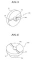
- FIG. 5 there is provided a perspective view of the rotating cam 121 of the cam assembly 15 shown in Fig. 3.
- the cross section of each of the protrusions 20 formed on the front surface of the rotating plate 21 and disposed thereon at about 180° is of an obtuse (or acute) angled triangular shape which increases in size from the center portion of the rotating plate 21 to the outer periphery thereof.
- An upper end of the coupling shaft 21a fixed at the central portion on the front surface of the rotating plate 21 is provided with a linear screw groove 21b.
- the connection member 21c is of a hollow cylindrical shape and has a screw thread formed on the inner surface thereof, whereby it is rigidly coupled to a screw thread formed at one end portion of the gear motor 16's output shaft 16a.
- Fig. 6 illustrates a perspective view of the actuating cam 123 of the cam assembly 15 shown in Fig. 3.
- Each of the protrusions 20 formed on the front surface of the actuating plate 23 and disposed thereon at about 180° is of an obtuse (or acute) angled triangular shape which increases in size from the center portion of the actuating plate 23 to the outer periphery thereof.
- the coupling hole 22a into which the coupling shaft 21a of the rotating cam 121 is to be rotatably and slidably inserted is provided at the central portion of the front surface of the actuating plate 23.
- valve actuating apparatus 5 for use in a high-pressure gas cylinder is fixedly coupled to the outlet side of the CO 2 storage cylinder 4 to house the valve 11 of the CO 2 storage cylinder 4.
- a device for generating a signal demanding a supply of CO 2 gas into the carbonator 3, e.g., a pressure sensor for detecting an internal pressure of the carbonator 3 is installed inside the carbonator 3. If such a signal from the device is transmitted to a controller (not shown) to demand the supply of the CO 2 gas into the carbonator 3, the controller controls the gear motor 16 to rotate the output shaft 16a for a predetermined period of time.
- the rotating cam 121 fixedly coupled to the output shaft 16a is also made to rotate. Then, the _protrusions 20 formed on the front surface of the rotating plate 21 of the rotating cam 121 are made to slide on the front surface of the actuating plate 23 of the actuating camp 123.
- the actuating plate 23 and the pressing member 23a of the actuating cam 123 begin to be pushed backward within the grooves 40b and the guide grooves 40c of the partition 40a of the upper and the lower casing 40, and, when crests of the protrusions 20 on the rotating plate 21 come into contact with crests of the protrusions 20 on the actuating plate 23, the actuating cam 123 is pushed backward at its maximum.
- the button 11b of the valve 11 is completely pressed by the pressing member 23a of the actuating cam 123, whereby the CO 2 gas is allowed to be discharged out of the CO 2 storage cylinder 4. Then, the discharged CO 2 gas is supplied into the carbonator 3 via the CO 2 gas supply conduit 9.
- the actuating cam 123 begins to be returned to its initial position due to an elastic force of the spring 11a disposed between the button 11b of the valve 11 and the valve body 11b or due to the internal pressure of the CO 2 storage cylinder 4, and, when the protrusions 20 on the front surface of the rotating plate 21 completely pass the protrusions 20 on the front surface of the actuating plate 23 and come into contact with the front surface of the actuating plate 23, the actuating cam 123 arrives in its initial position completely. As a result, the valve 11 is closed, and the discharge of the CO 2 gas from the CO 2 gas storage cylinder 4 is stopped.
- the valve 11 is pressed and its pressed state is released repeatedly by the operation of the rotating cam 121 and the actuating cam 123 as described above.
- the supply of the CO 2 gas into the carbonator 3 is carried out intermittently, which makes it possible to supply the CO 2 gas into the carbonator 3 from the CO 2 storage cylinder 4 containing the high-pressure CO 2 gas therein without imposing a high pressure on the carbonator 3.
- the discharged amount of the CO 2 gas from the CO 2 storage cylinder 4 can be controlled precisely.
- the number of the valve 11's button 11b being pressed per unit time can be controlled by adjusting the rotational speed of the output shaft 16a of the gear motor 16.
- Fig. 7 illustrates a first modification of the rotating cam 121 shown in Fig. 5.
- two pairs of protrusions 20 are formed on the front surface of the rotating plate 21 by an angular interval of 90°. Therefore, in case the output shaft 16a of the gear motor 16 is rotated at the same rotational speed as in the case of using the rotating cam 121 shown in Fig. 5, the number of pressing the button 11b of the valve 11 per unit time increases twice, which makes it possible to increase the amount of the CO 2 gas discharged from the CO 2 storage cylinder 4 per unit time twice without increasing the rotational speed of the output shaft 16a of the gear motor 16.
- Fig. 8 illustrates a second modification of the rotating cam 121 shown in Fig. 5.
- a pair of protrusions 20a is formed on the front surface of the rotating plate 21 by an angular interval of 180°.
- the cross section of each protrusion 20a is of an obtuse (or acute) angled triangular shape which increases in size from the center portion of the rotating plate 21 to the outer periphery thereof, as in the preferred embodiment shown in Fig. 5.
- the protrusions 20a in this example are not formed linearly from the center portion to the outer periphery of the rotating plate 21 but are curved.
- protrusions of an actuating plate 23 are also similarly curved.
- Fig. 9 illustrates a third modification of the rotating cam 121 shown in Fig. 5.
- a pair of protrusions 20b is formed on the front surface of a rotating plate by an angular interval of 180°.
- the cross section of each protrusions 20b is of a right-angled triangular shape. Therefore, in a case where the protrusions 20b are formed on the front surfaces of the actuating cam 121c and the rotating cam 123c as shown in Fig. 10, although the rotating cam 121 is capable of rotating in a direction indicated by an arrow A, the rotation of the rotating cam 121c in the reverse direction is limited within a preset degree range.
- valve actuating apparatus for use in the high-pressure gas cylinder
- carbonating apparatus for use in the refrigerator
- various appliances equipped with carbonators for example, a drinking water dispenser.
- valve actuating apparatus for use in the high-pressure gas cylinder to the CO 2 storage cylinder containing the high-pressure CO 2 gas therein, it can also be applied to various high-pressure gas cylinders containing diverse high-pressure gases other than the CO 2 gas.
- the CO 2 gas can be supplied into the carbonator of the carbonating apparatus from the CO 2 storage cylinder intermittently, the imposing of a high pressure on the carbonator can be prevented. Accordingly, the supply of the CO 2 gas into the carbonator from the CO 2 storage cylinder can be carried out safely. Furthermore, by controlling the rotation number or the rotational speed of the gear motor, a required amount of CO 2 gas can be supplied into the carbonator accurately.
Landscapes
- Engineering & Computer Science (AREA)
- General Engineering & Computer Science (AREA)
- Mechanical Engineering (AREA)
- Mechanically-Actuated Valves (AREA)
- Devices For Dispensing Beverages (AREA)
- Filling Or Discharging Of Gas Storage Vessels (AREA)
Claims (8)
- Ventil-Betätigungseinrichtung (5) für die Verwendung in einem Hochdruck-Gaszylinder (4), umfassend:ein Gehäuse (40) für eine feste Verbindung mit dem Hochdruck-Gaszylinder (4), das ein Ventil (11) des Hochdruck-Gaszylinders (4) aufnimmt;ein Betätigungs-Nockenelement (123), das derart im Gehäuse angeordnet ist, dass es zum Ausüben von Druck auf das Ventil (11) des Hochdruck-Gaszylinders (4) linear bewegbar ist;ein rotierbar im Gehäuse (40) angeordnetes rotierendes Nockenelement (121); undeine mit dem Gehäuse (40) verbundene Antriebseinheit (16) zum Beaufschlagen des rotierenden Nockenelements mit einer Drehkraft,dadurch gekennzeichnet, dass das rotierende Nockenelement (121) eine rotierende Scheibe (21) und einen an einer Vorderseite der rotierenden Scheibe (21) ausgebildeten Vorsprung (20) umfasst; das Betätigungs-Nockenelement (123) eine Betätigungsscheibe (23) und einen an einer Vorderseite der Betätigungsscheibe (23) ausgebildeten Vorsprung (20) umfasst; und das rotierende Nockenelement (121) und das Betätigungs-Nockenelement (123) einander kontaktieren.
- Ventil-Betätigungseinrichtung (5) nach Anspruch 1, bei der das Gehäuse (40) eine in seinem Inneren ausgebildete und mit einer Öffnung versehene Abtrennung (40a) vorsieht; das Betätigungs-Nockenelement (123) ein an einer Rückseite der Betätigungsscheibe (23) befestigtes Drückelement (23a) und ein an einer Seitenwand des Drückelements (23a) befestigtes Gleitelement (23b) umfasst; und das Drückelement (23a) und das Gleitelement (23b) gleitend in die in der Abtrennung (40a) vorgesehene Öffnung geführt sind.
- Ventil-Betätigungseinrichtung (5) nach Anspruch 1, bei welcher das rotierende Nockenelement eine an einem mittigen Abschnitt der Vorderseite der rotierenden Scheibe befestigte Koppelstange (21a) umfasst; das Betätigungs-Nockenelement (123) eine an einem mittigen Abschnitt der Betätigungsscheibe (23) ausgebildete Koppelvertiefung (22a) umfasst; und die Koppelstange (21a) in die Koppelvertiefung (22a) eingeführt ist.
- Ventil-Betätigungseinrichtung (5) nach Anspruch 3, bei welcher das rotierende Nockenelement (121) außerdem ein an einer Rückseite der rotierenden Scheibe (21) befestigtes, hohles, zylindrisches Verbindungselement (21c) umfasst; ein Schraubgewinde an der Innenseite des Verbindungselements (21c) ausgebildet ist; und ein Schraubschlitz an einem Ende der Koppelstange (21a) ausgebildet ist.
- Ventil-Betätigungseinrichtung (5) nach Anspruch 1, bei welcher der Vorsprung (20) der rotierenden Scheibe (21) von einem mittigen Abschnitt zu einem äußeren Randbereich der rotierenden Scheibe (21) linear ausgebildet ist und ein Querschnitt des Vorsprungs (20) eine stumpf- oder spitzwinklige Dreiecksform aufweist.
- Ventil-Betätigungseinrichtung (5) nach Anspruch 1, bei welcher der Vorsprung (20) der rotierenden Scheibe (21) von einem mittigen Abschnitt zu einem äußeren Randbereich der Betätigungsscheibe (21) gekrümmt ausgebildet ist und ein Querschnitt des Vorsprungs (20) eine stumpf- oder spitzwinklige Dreiecksform aufweist.
- Ventil-Betätigungseinrichtung (5) nach Anspruch 1, bei welcher der Vorsprung (20) der rotierenden Scheibe (121) von einem mittigen Abschnitt zu einem äußeren Randbereich der rotierenden Scheibe (21) ausgebildet ist und ein Querschnitt des Vorsprungs (20) eine rechtwinklige Dreiecksform aufweist.
- Karbonisierungsapparat zum Erzeugen von karbonisiertem Wasser unter Verwendung der Ventil-Betätigungseinrichtung nach einem der Ansprüche 1 bis 7.
Applications Claiming Priority (2)
| Application Number | Priority Date | Filing Date | Title |
|---|---|---|---|
| KR2004044577 | 2004-06-16 | ||
| KR1020040044577A KR100588842B1 (ko) | 2004-06-16 | 2004-06-16 | 고압가스 공급장치 |
Publications (2)
| Publication Number | Publication Date |
|---|---|
| EP1607664A1 EP1607664A1 (de) | 2005-12-21 |
| EP1607664B1 true EP1607664B1 (de) | 2008-01-23 |
Family
ID=34936083
Family Applications (1)
| Application Number | Title | Priority Date | Filing Date |
|---|---|---|---|
| EP05009681A Expired - Lifetime EP1607664B1 (de) | 2004-06-16 | 2005-05-03 | Ventilsteuerungseinrichtung |
Country Status (3)
| Country | Link |
|---|---|
| EP (1) | EP1607664B1 (de) |
| KR (1) | KR100588842B1 (de) |
| DE (1) | DE602005004445T2 (de) |
Cited By (3)
| Publication number | Priority date | Publication date | Assignee | Title |
|---|---|---|---|---|
| US20130026665A1 (en) * | 2010-04-09 | 2013-01-31 | Electrolux Home Products Corporation N.V. | Fluid mixing apparatus |
| US12005408B1 (en) | 2023-04-14 | 2024-06-11 | Sharkninja Operating Llc | Mixing funnel |
| US12017192B1 (en) | 2023-06-16 | 2024-06-25 | Sharkninja Operating Llc | Carbonation mixing nozzles |
Families Citing this family (2)
| Publication number | Priority date | Publication date | Assignee | Title |
|---|---|---|---|---|
| US10815114B2 (en) | 2016-12-27 | 2020-10-27 | Midnight Madness Distilling, Llc | Effervescent liquid dispenser |
| CN113213410A (zh) | 2017-07-25 | 2021-08-06 | 米德耐特麦德尼斯蒸馏有限责任公司 | 起泡液体分配器 |
Family Cites Families (5)
| Publication number | Priority date | Publication date | Assignee | Title |
|---|---|---|---|---|
| GB197130A (en) * | 1922-03-16 | 1923-05-10 | Vincent Pompa | Improvements in supply taps for soda fountains and the like |
| DE3537787A1 (de) * | 1985-10-24 | 1987-04-30 | Bosch Gmbh Robert | Unterdrucksteuerventil, insbesondere zum steuern eines abgasrueckfuehrventils fuer brennkraftmaschinen |
| EP0947474A3 (de) * | 1998-03-30 | 2000-01-26 | Guldager A/S | Einrichtung zur CO2 Dosierung zum Wasser |
| DE19855170A1 (de) * | 1998-11-30 | 2000-05-31 | Sparkling Kraemer Gmbh | Vorrichtung zur Karbonisierung von Getränken |
| US6588724B2 (en) * | 2001-08-15 | 2003-07-08 | Jetec Company | On-off valves for high pressure fluids |
-
2004
- 2004-06-16 KR KR1020040044577A patent/KR100588842B1/ko not_active Expired - Fee Related
-
2005
- 2005-05-03 EP EP05009681A patent/EP1607664B1/de not_active Expired - Lifetime
- 2005-05-03 DE DE602005004445T patent/DE602005004445T2/de not_active Expired - Lifetime
Cited By (5)
| Publication number | Priority date | Publication date | Assignee | Title |
|---|---|---|---|---|
| US20130026665A1 (en) * | 2010-04-09 | 2013-01-31 | Electrolux Home Products Corporation N.V. | Fluid mixing apparatus |
| US12005408B1 (en) | 2023-04-14 | 2024-06-11 | Sharkninja Operating Llc | Mixing funnel |
| US12616945B2 (en) | 2023-04-14 | 2026-05-05 | Sharkninja Operating Llc | Mixing funnel |
| US12017192B1 (en) | 2023-06-16 | 2024-06-25 | Sharkninja Operating Llc | Carbonation mixing nozzles |
| US12533643B2 (en) | 2023-06-16 | 2026-01-27 | Sharkninja Operating Llc | Carbonation mixing nozzles |
Also Published As
| Publication number | Publication date |
|---|---|
| KR100588842B1 (ko) | 2006-06-14 |
| DE602005004445D1 (de) | 2008-03-13 |
| DE602005004445T2 (de) | 2009-01-15 |
| KR20050119471A (ko) | 2005-12-21 |
| EP1607664A1 (de) | 2005-12-21 |
Similar Documents
| Publication | Publication Date | Title |
|---|---|---|
| US9302229B2 (en) | Method for producing a carbonated beverage | |
| MX2010012548A (es) | Dispositivo dispensador de fluido regulado de construccion modular. | |
| US4715516A (en) | Apparatus for dispensing carbonated beverage from containers | |
| US6386403B2 (en) | Gas-driven liquid dispenser employing separate pressurized-gas source | |
| EP2331895B1 (de) | Kühlschrank mit ausgabevorrichtung | |
| WO2011026013A1 (en) | Elastomeric flow control device for a bar gun manifold | |
| US20090283540A1 (en) | Regulated fluid dispensing device and method of dispensing a carbonated beverage | |
| KR900700017A (ko) | 냉동제품 분배장치 | |
| WO2008048098A1 (en) | Device for dispensing a fluid | |
| CA2343138A1 (en) | Taps and containers for dispensing fluid | |
| MX2013004729A (es) | Instrumento de dosificacion provisto con una cubierta articulada. | |
| CA2372290A1 (en) | Dispensing valve for fluids | |
| JPH0314500A (ja) | 液体を分配する装置 | |
| CN1964901A (zh) | 用于由容器的空腔输出流体的装置 | |
| KR20130108500A (ko) | 유체 혼합 장치 | |
| RU2591088C2 (ru) | Приспособление для разлива жидкости, оснащенное противокапельной клапанной системой | |
| EP1607664A1 (de) | Ventilsteuerungseinrichtung | |
| US20100293986A1 (en) | Water supply device of refrigerator | |
| US6626213B2 (en) | Drink dispenser device for domestic refrigerators | |
| US11473278B2 (en) | Switching technology for faucets | |
| WO2009020256A1 (en) | Fluid dispenser for dispensing fixed amount of fluid | |
| CN223049512U (zh) | 龙头 | |
| WO2006043246A1 (en) | Beverage dispenser | |
| KR200283545Y1 (ko) | 유체 분배기 | |
| KR100262869B1 (ko) | 급유장치 |
Legal Events
| Date | Code | Title | Description |
|---|---|---|---|
| PUAI | Public reference made under article 153(3) epc to a published international application that has entered the european phase |
Free format text: ORIGINAL CODE: 0009012 |
|
| AK | Designated contracting states |
Kind code of ref document: A1 Designated state(s): AT BE BG CH CY CZ DE DK EE ES FI FR GB GR HU IE IS IT LI LT LU MC NL PL PT RO SE SI SK TR |
|
| AX | Request for extension of the european patent |
Extension state: AL BA HR LV MK YU |
|
| 17P | Request for examination filed |
Effective date: 20060601 |
|
| AKX | Designation fees paid |
Designated state(s): DE FR GB IT NL |
|
| 17Q | First examination report despatched |
Effective date: 20061023 |
|
| GRAP | Despatch of communication of intention to grant a patent |
Free format text: ORIGINAL CODE: EPIDOSNIGR1 |
|
| GRAS | Grant fee paid |
Free format text: ORIGINAL CODE: EPIDOSNIGR3 |
|
| GRAA | (expected) grant |
Free format text: ORIGINAL CODE: 0009210 |
|
| AK | Designated contracting states |
Kind code of ref document: B1 Designated state(s): DE FR GB IT NL |
|
| REG | Reference to a national code |
Ref country code: GB Ref legal event code: FG4D |
|
| REF | Corresponds to: |
Ref document number: 602005004445 Country of ref document: DE Date of ref document: 20080313 Kind code of ref document: P |
|
| PLBE | No opposition filed within time limit |
Free format text: ORIGINAL CODE: 0009261 |
|
| STAA | Information on the status of an ep patent application or granted ep patent |
Free format text: STATUS: NO OPPOSITION FILED WITHIN TIME LIMIT |
|
| 26N | No opposition filed |
Effective date: 20081024 |
|
| PGFP | Annual fee paid to national office [announced via postgrant information from national office to epo] |
Ref country code: FR Payment date: 20110513 Year of fee payment: 7 |
|
| PGFP | Annual fee paid to national office [announced via postgrant information from national office to epo] |
Ref country code: NL Payment date: 20110420 Year of fee payment: 7 Ref country code: GB Payment date: 20110418 Year of fee payment: 7 |
|
| PGFP | Annual fee paid to national office [announced via postgrant information from national office to epo] |
Ref country code: IT Payment date: 20110418 Year of fee payment: 7 Ref country code: DE Payment date: 20110414 Year of fee payment: 7 |
|
| REG | Reference to a national code |
Ref country code: NL Ref legal event code: V1 Effective date: 20121201 |
|
| GBPC | Gb: european patent ceased through non-payment of renewal fee |
Effective date: 20120503 |
|
| PG25 | Lapsed in a contracting state [announced via postgrant information from national office to epo] |
Ref country code: IT Free format text: LAPSE BECAUSE OF NON-PAYMENT OF DUE FEES Effective date: 20120503 |
|
| REG | Reference to a national code |
Ref country code: FR Ref legal event code: ST Effective date: 20130131 |
|
| REG | Reference to a national code |
Ref country code: DE Ref legal event code: R119 Ref document number: 602005004445 Country of ref document: DE Effective date: 20121201 |
|
| PG25 | Lapsed in a contracting state [announced via postgrant information from national office to epo] |
Ref country code: NL Free format text: LAPSE BECAUSE OF NON-PAYMENT OF DUE FEES Effective date: 20121201 |
|
| PG25 | Lapsed in a contracting state [announced via postgrant information from national office to epo] |
Ref country code: FR Free format text: LAPSE BECAUSE OF NON-PAYMENT OF DUE FEES Effective date: 20120531 Ref country code: GB Free format text: LAPSE BECAUSE OF NON-PAYMENT OF DUE FEES Effective date: 20120503 |
|
| PG25 | Lapsed in a contracting state [announced via postgrant information from national office to epo] |
Ref country code: DE Free format text: LAPSE BECAUSE OF NON-PAYMENT OF DUE FEES Effective date: 20121201 |