EP1607831A2 - Verriegelungsvorrichtung für ein herausnehmbares Erweiterungsmodul - Google Patents
Verriegelungsvorrichtung für ein herausnehmbares Erweiterungsmodul Download PDFInfo
- Publication number
- EP1607831A2 EP1607831A2 EP05252736A EP05252736A EP1607831A2 EP 1607831 A2 EP1607831 A2 EP 1607831A2 EP 05252736 A EP05252736 A EP 05252736A EP 05252736 A EP05252736 A EP 05252736A EP 1607831 A2 EP1607831 A2 EP 1607831A2
- Authority
- EP
- European Patent Office
- Prior art keywords
- latch
- expansion module
- module
- recess
- sleeve
- Prior art date
- Legal status (The legal status is an assumption and is not a legal conclusion. Google has not performed a legal analysis and makes no representation as to the accuracy of the status listed.)
- Withdrawn
Links
Images

Classifications
-
- G—PHYSICS
- G06—COMPUTING OR CALCULATING; COUNTING
- G06F—ELECTRIC DIGITAL DATA PROCESSING
- G06F1/00—Details not covered by groups G06F3/00 - G06F13/00 and G06F21/00
- G06F1/16—Constructional details or arrangements
- G06F1/18—Packaging or power distribution
- G06F1/183—Internal mounting support structures, e.g. for supporting printed circuit boards
- G06F1/184—Mounting of motherboards
-
- G—PHYSICS
- G06—COMPUTING OR CALCULATING; COUNTING
- G06F—ELECTRIC DIGITAL DATA PROCESSING
- G06F1/00—Details not covered by groups G06F3/00 - G06F13/00 and G06F21/00
- G06F1/16—Constructional details or arrangements
- G06F1/18—Packaging or power distribution
- G06F1/183—Internal mounting support structures, e.g. for supporting printed circuit boards
- G06F1/187—Mounting of fixed or removable disk drives
Definitions
- the present invention relates to an apparatus for a removable expansion module latch system.
- any rotating latch that would work well in a sleeve application would having protruding elements that are not useful when outside the sleeve in an external usage application.
- the present invention provides a removable expansion module latch system.
- An expansion module latch mechanism includes an expansion module and a latch release.
- the expansion module has a recess for receiving a retaining latch external to the expansion module for retaining the expansion module positioned with respect to an expansion module sleeve.
- the latch release is attached to the expansion module for expelling a retained latch from the recess.
- An expansion module bay latch mechanism retains an expansion module positioned with respect to a module sleeve.
- the expansion module bay latch mechanism has a module sleeve having a latch clip positioned on a side wall of the module sleeve.
- the latch clip includes a latch adapted to interfit with a recess in an expansion module and a paddle connected to the latch which, in response to contact with the expansion module, urges the latch into the recess.
- a releasable expansion module latch system includes the above-described expansion module sleeve retaining the above-described expansion module inserted in the expansion module sleeve.
- the mechanism of the present invention provides a releasable latch for an expansion module of a computer system.
- a releasable latch according to an embodiment of the present invention enables one-handed operation to quickly and easily install and latch, as well as unlatch and remove, an expansion module, e.g., having a hard drive, from an expansion module bay in a computer system.
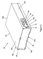
- Expansion module 10 is a rounded rectangular enclosure for receiving an expansion device (not shown), e.g., a hard disk drive.
- Expansion module 10 includes a housing 12 including an upper rectangular channel 14 having a generally U-shaped cross-section connected to a lower rectangular channel 16 having a generally U-shaped cross-section to form a rounded rectangular enclosure having a rounded rectangular opening at each end.
- a pair of C-shaped connecting strips 18, 20 join the open ends of the U-shaped channels 14, 16 to each other.
- C-shaped connecting strips 18, 20 and the mechanism for joining U-shaped channels 14, 16 are more fully described in co-pending U.S. Patent application titled, "Removable Information Storage Device Enclosure.”
- upper rectangular channel 14 and lower rectangular channel 16 are made of a thermally conductive material to assist in removing heat from within the expansion module 10.
- housing 12 may have a non-rounded rectangular cross-section, an oval or circular cross-section, and a polygonal cross-section.
- a first end cap 22 having a rounded rectangular cross-section similar to housing 12, attaches at one open end of housing 12 thereby closing the opening. End cap 22 closes the open end of housing 12 to prevent entry of dust and other contaminants and retain expansion device (not shown) within the housing 12 interior.
- End cap 22 includes a pair of latch releases 23 (partially shown) for inserting and removing expansion module 10 from an expansion module bay 60 ( Figure 2) described in detail below. Operation of latch release 23 is described in detail below with reference to Figure 5.
- End cap 22 further includes a pair of recesses 26 along each side of the end cap and generally aligned with connecting strips 18, 20 for receiving a latch 76 (Figure 2) to retain module 10 in expansion module bay 60 ( Figure 2).
- end cap 22 includes a single recess 26 along one side and a single latch release 23 toward the distal side of the end cap from the single recess.
- end cap 22 attaches to one of rectangular channels 14, 16 and the other rectangular channel 16, 14 attaches to the first rectangular channel via connecting strips 18, 20, as described above. In this manner, end cap 22 need not be removed in order to access housing 12 interior.
- End cap 24 described in further detail in conjunction with the above-reference co-pending application, closes the open end of housing 12 to minimize entry of dust and other contaminants and retain expansion device (not shown) within the housing 12 interior and includes connectors for providing power to and transmitting and receiving data signals to/from module 10.
- end cap 24 attaches to one of rectangular channels 14, 16 and the other rectangular channel 16, 14 attaches to the first rectangular channel via connecting strips 18, 20, as described above. In this manner, end cap 24 need not be removed in order to access housing 12 interior.
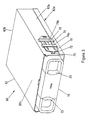
- FIG. 2 depicts an expansion module bay 60 according to an embodiment of the present invention for receiving the above-described expansion module 10.
- Module bay 60 includes an elongated parallelepiped module sleeve 62 having a front opening 62a in one face and a rear face 62b for receiving connectors from a computer system (not shown).
- Front opening 62a is sized to receive expansion module 10 to the interior of module bay 60.
- Module sleeve 62 further includes a top side 62c, a bottom side 62d (not shown), a right side wall 62e, and a left side wall 62f (not shown).
- a bay door 66 substantially covers front opening 62a of module bay 60.
- Bay door 66 attaches rotatably module bay 60 at either end of the door and remains in place over front opening 62a by the force of spring 68 mounted at one end of front opening 62a.
- Module 10 insertion force moves bay door 66 upward by contact with a leading edge of the module.
- Module bay 60 is mounted within a standard drive bay of a computer system (not shown) via standard mounting hardware and a connector (not shown) connects to rear face 62b to provide data and power connections to module 10 when inserted in module bay 60.
- Module sleeve 62 includes a latch clip 70 mounted on right side wall 62e for retaining an inserted expansion module 10.
- Module sleeve 62 includes a second latch clip (not shown) mounted on left side wall 62f in the same configuration and operation of latch clip 70 and therefore only latch clip 70 is described below.
- Latch clip 70 extends in a direction parallel to the right side wall 62e and is positioned over a side wall opening 72. Retaining ribs 74a, 74b, formed as part of right side wall 62e of sleeve 62, retain the latch clip 70 in position with respect to opening 72 and connect either side of opening 72 from near the top of right side wall 62e to near the bottom of the right side wall.
- retaining ribs 74a, 74b may be replaced by a single retaining rib and are attached rather than being formed as a part of side wall 62e.
- Latch clip 70 fits between right side wall 62e and retaining ribs 74a, 74b.
- Latch clip 70 is substantially flat, except as noted and described below, and approximately the same thickness as side wall 62e.
- Latch clip 70 has a central substantially rectangular opening 75.
- latch clip 70 has a generally hexagonal shape larger than generally hexagonal-shaped opening 72.
- Latch clip 70 includes a latch 76 at the end closest to front face 62a of sleeve 62 and a paddle 78 positioned within central opening 75 between latch 76 and the distal end of latch 76 and connected to latch 76.
- Latch 76 protrudes from the end of latch clip 70 in a direction generally perpendicular to the length of latch clip 70 as installed along right side wall 62e and inward toward the interior of module sleeve 62.
- Latch 76 forms a V shape as viewed from above, e.g., looking down on the top face 62c of module sleeve 62.
- Paddle 78 extends along the mid-section of latch clip 70 from the side of opening 75 nearest latch 76 toward the opposite side of opening 75.
- a proximal region 80 ( Figure 4) of paddle 78 connects the paddle to the edge of opening 75 and extends in a direction parallel with latch clip 70 toward the opposite side of opening 75.
- a distal region 82 ( Figure 4) of paddle 78 connects to the end of proximal region 80 and extends at an oblique angle from proximal region 80 toward rear face 62b and the interior of sleeve 62.
- Latch 76 and paddle 78 are connected via a portion of latch clip 70 such that movement of distal region 78 in one direction causes movement of latch 76 in the opposite direction, e.g., as distal region 78 moves toward the exterior of sleeve 62, latch 76 moves toward the interior of sleeve 62.
- latch clip 70 is biased such that distal region 82 of paddle 78 extends into the interior of sleeve 62 through opening 72 of right side wall 62e of sleeve 62 and also through opening 75 of the latch clip. Further, prior to insertion of module 10 into module bay 60, latch 76 does not intrude into the interior of sleeve 62.
- one side of the module contacts distal region 82 of paddle 78 and urges the distal region in a direction toward the exterior of sleeve 62, i.e., toward opening 75 of latch clip 70.
- Retaining rib 74a prevents latch clip 70 from moving outward from sleeve 62 and acts as a pivot point causing the end of latch clip 70 having latch 76 attached to move toward the interior of sleeve 62 and thereby urge latch 76 inward.
- Figure 3 depicts an expansion module bay 60 according to an embodiment of the present invention having the above-described expansion module 10 positioned within the interior of the module bay and latch 76 interfit in recess 26 of the module.
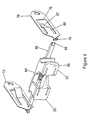
- Figure 4 depicts a pair of latch releases 23 and a pair of latch clips 70 according to an embodiment of the present invention positioned as depicted in Figure 3 without depicting the expansion module bay 60 and the expansion module 10.
- a tension spring 84 connects the pair of latch releases 23 and urges the releases toward each other, i.e., tension spring 84 pulls each latch release away from a respective recess 26 when installed in module 10 and toward the other latch release.
- Latch release 23 includes a latch release grip 86 at one end and a latch release actuator 88 at the distal end from the latch release grip.
- the end of latch release actuator 88 includes a tip 90 for contacting latch 76.
- Each end of tension spring 84 is connected to one of the pair of latch releases 23 between grip 86 and actuator 88 of a respective latch release 23.
- the pair of latch releases 23 are shaped to interfit with each other facing in opposite directions and slide alongside each other until grips 86 of each latch release are adjacent to each other.
- a user grips the pair of latch releases 23 and urges the releases toward each other against tension spring 84 resistance thereby bringing the latch release tip 90 into contact with latch 76 and urging latch 76 out of recess 26 away from interior of sleeve 62.
- the user is able to withdraw expansion module 10 from expansion module bay 60.
- paddle 78 moves toward the interior of sleeve 62 and latch 76 moves toward the exterior of sleeve 62 thereby allowing door 66 to rotate closed.
- latch 76 does not protrude into the sleeve interior until actuated by insertion of module 10.
- latch release actuator 88 does not protrude exterior of the end cap 22 until latch release 23 is actuated by a user and thereby presenting fewer external features of module 10 to be caught or damaged.
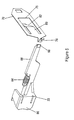
- Figure 5 depicts one latch release 23 and the corresponding latch clip 70 of the pair of latch releases and latch clips depicted in Figure 4 in order to more clearly display the shape of the latch release.
- end cap 22 includes an attachment point (not shown) for connecting one end of tension spring 84 enabling use of a single latch clip 70 in conjunction with a single latch release 23 to retain an expansion module 10 in an expansion module bay 60.
- a user need only move the single latch release 23 with respect to end cap 22 in order to release latch 76 from recess 26 in order to enable removal of module 10 from module bay 60.
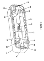
- FIG. 6 depicts the interior side of end cap 22.
- End cap 22 includes the pair of latch releases 23 arranged along the center of the end cap and positioned such that the pair of latch release actuators 88 slide along a pair of channels 92 at either side of end cap 22.
- Channel 92 is connected to and opens to the base of recess 26 in order to allow latch release tip 90 to slide along channel 92 and, in operation, protrude from the base of the recess to contact latch 76 and urge the latch out of the recess.
- End cap 22 includes four receiving mounts 94 spaced about the interior of the end cap for receiving fasteners from housing 12 to secure the end cap to the housing.
- the latch release actuator 88 remains within the boundary of the module 10 and does not rotate or protrude out in an external usage situation such as using a rotating lever. Also, from an industrial design standpoint, the latch design in the front side of expansion module 10 and expansion module bay 60 is symmetrical and presents a clean appearance outside the sleeve 62 in an external situation without having an offset lever with no visible use.
Landscapes
- Engineering & Computer Science (AREA)
- Theoretical Computer Science (AREA)
- Computer Hardware Design (AREA)
- Power Engineering (AREA)
- Human Computer Interaction (AREA)
- Physics & Mathematics (AREA)
- General Engineering & Computer Science (AREA)
- General Physics & Mathematics (AREA)
- Casings For Electric Apparatus (AREA)
Applications Claiming Priority (2)
| Application Number | Priority Date | Filing Date | Title |
|---|---|---|---|
| US836342 | 2004-05-03 | ||
| US10/836,342 US20050243534A1 (en) | 2004-05-03 | 2004-05-03 | Removable expansion module latch system |
Publications (1)
| Publication Number | Publication Date |
|---|---|
| EP1607831A2 true EP1607831A2 (de) | 2005-12-21 |
Family
ID=35094318
Family Applications (1)
| Application Number | Title | Priority Date | Filing Date |
|---|---|---|---|
| EP05252736A Withdrawn EP1607831A2 (de) | 2004-05-03 | 2005-05-03 | Verriegelungsvorrichtung für ein herausnehmbares Erweiterungsmodul |
Country Status (3)
| Country | Link |
|---|---|
| US (1) | US20050243534A1 (de) |
| EP (1) | EP1607831A2 (de) |
| CN (1) | CN1694038A (de) |
Families Citing this family (8)
| Publication number | Priority date | Publication date | Assignee | Title |
|---|---|---|---|---|
| US7403382B2 (en) | 2004-05-03 | 2008-07-22 | Hewlett-Packard Development Company, L.P. | Removable expansion module usable as internal and external device |
| US8203851B2 (en) * | 2009-02-09 | 2012-06-19 | Juniper Networks, Inc. | Retention-extraction device for removable cards in a chassis |
| CN104571380B (zh) * | 2013-10-28 | 2018-07-10 | 纬创资通股份有限公司 | 锁固机构及箱型设备 |
| US9125318B2 (en) * | 2013-11-26 | 2015-09-01 | Lenovo Enterprise Solutions (Singapore) Pte. Ltd. | Handle lockout mechanism for scaling blade-style servers |
| USD789931S1 (en) * | 2016-03-10 | 2017-06-20 | Drew Technologies, Inc. | Vehicle data acquisition device |
| USD813836S1 (en) * | 2016-05-31 | 2018-03-27 | JVC Kenwood Corporation | Audio amplifier for automobile |
| US10674620B2 (en) * | 2018-09-27 | 2020-06-02 | Cisco Technology, Inc. | Removable module adapter for modular electronic system |
| US12543286B2 (en) * | 2023-05-01 | 2026-02-03 | Western Digital Technologies, Inc. | Storage device carrier and latching mechanism |
Family Cites Families (6)
| Publication number | Priority date | Publication date | Assignee | Title |
|---|---|---|---|---|
| US3953094A (en) * | 1973-11-30 | 1976-04-27 | Wangco Incorporated | Cabinet configuration for loading disc drive apparatus |
| JPS6019879Y2 (ja) * | 1977-09-27 | 1985-06-14 | 株式会社糸井製作所 | 引き出し付収納庫 |
| NL8303946A (nl) * | 1983-11-17 | 1985-06-17 | Philips Nv | Inbouwapparaat met een montageveer. |
| US5441421A (en) * | 1993-06-11 | 1995-08-15 | American International Pacific Industries Corporation | Anti-theft mounting system for vehicle radio or stereo equipment |
| US5520069A (en) * | 1994-10-31 | 1996-05-28 | Hewlett-Packard Company | Synchronized lever mechanism for insertion and removal of modules in housings |
| GB9515982D0 (en) * | 1995-08-04 | 1995-10-04 | Havant International Ltd | Disk file mounting |
-
2004
- 2004-05-03 US US10/836,342 patent/US20050243534A1/en not_active Abandoned
-
2005
- 2005-05-03 EP EP05252736A patent/EP1607831A2/de not_active Withdrawn
- 2005-05-08 CN CN200510069702.6A patent/CN1694038A/zh active Pending
Also Published As
| Publication number | Publication date |
|---|---|
| US20050243534A1 (en) | 2005-11-03 |
| CN1694038A (zh) | 2005-11-09 |
Similar Documents
| Publication | Publication Date | Title |
|---|---|---|
| CN101893919B (zh) | 数据存储器固定装置 | |
| US20090255099A1 (en) | Latch apparatus | |
| US9203188B1 (en) | Single-motion trigger ejector with optical switch actuator | |
| EP3110020B1 (de) | Elektronische vorrichtung mit kartenfach | |
| US6587350B1 (en) | Ejection mechanism for modular electronic element | |
| KR100428794B1 (ko) | 컴퓨터용 주변 기기 착탈용 도킹 기구 | |
| EP2371037B1 (de) | Frontplatte mit staubdichter blende | |
| US7559782B2 (en) | Storage device box | |
| US20070001559A1 (en) | Computer enclosure with locking device | |
| US20090091884A1 (en) | Storage device carrier | |
| JP5718300B2 (ja) | 着脱機構、装着装置、電子機器 | |
| US7374347B1 (en) | Optical pluggable transceiver with securable latching mechanism | |
| US20090124138A1 (en) | Apparatus For Plug-In And Plug-Out Protection | |
| US7575453B2 (en) | Electronic module locking and ejecting apparatus | |
| JPH04369014A (ja) | ハードディスクパックの脱着機構 | |
| US20080165486A1 (en) | Computer front bezel | |
| US20040214077A1 (en) | Battery locking apparatus for electronic device | |
| US6547347B2 (en) | Device unit housing apparatus | |
| EP1607831A2 (de) | Verriegelungsvorrichtung für ein herausnehmbares Erweiterungsmodul | |
| US20080117584A1 (en) | Latching mechanism | |
| CN115054302B (zh) | 腔镜切割吻合器组件 | |
| US7430115B2 (en) | Apparatus for mounting removably a disk drive in an electronic device | |
| CN114585201A (zh) | 机箱及其扩充匣 | |
| US20040213141A1 (en) | Storage device assembly incorporating ejecting mechanism with safety latch | |
| US7359190B2 (en) | Interface for expansion module and expansion module bay |
Legal Events
| Date | Code | Title | Description |
|---|---|---|---|
| PUAI | Public reference made under article 153(3) epc to a published international application that has entered the european phase |
Free format text: ORIGINAL CODE: 0009012 |
|
| AK | Designated contracting states |
Kind code of ref document: A2 Designated state(s): AT BE BG CH CY CZ DE DK EE ES FI FR GB GR HU IE IS IT LI LT LU MC NL PL PT RO SE SI SK TR |
|
| AX | Request for extension of the european patent |
Extension state: AL BA HR LV MK YU |
|
| STAA | Information on the status of an ep patent application or granted ep patent |
Free format text: STATUS: THE APPLICATION HAS BEEN WITHDRAWN |
|
| 18W | Application withdrawn |
Effective date: 20070130 |