EP1607977A2 - Elektronisces Gerät mit eingebauter Platteneinrichtung - Google Patents
Elektronisces Gerät mit eingebauter Platteneinrichtung Download PDFInfo
- Publication number
- EP1607977A2 EP1607977A2 EP05253666A EP05253666A EP1607977A2 EP 1607977 A2 EP1607977 A2 EP 1607977A2 EP 05253666 A EP05253666 A EP 05253666A EP 05253666 A EP05253666 A EP 05253666A EP 1607977 A2 EP1607977 A2 EP 1607977A2
- Authority
- EP
- European Patent Office
- Prior art keywords
- disk device
- flat cable
- flexible flat
- built
- electronic device
- Prior art date
- Legal status (The legal status is an assumption and is not a legal conclusion. Google has not performed a legal analysis and makes no representation as to the accuracy of the status listed.)
- Withdrawn
Links
Images







Classifications
-
- G—PHYSICS
- G11—INFORMATION STORAGE
- G11B—INFORMATION STORAGE BASED ON RELATIVE MOVEMENT BETWEEN RECORD CARRIER AND TRANSDUCER
- G11B33/00—Constructional parts, details or accessories not provided for in the other groups of this subclass
- G11B33/12—Disposition of constructional parts in the apparatus, e.g. of power supply, of modules
- G11B33/121—Disposition of constructional parts in the apparatus, e.g. of power supply, of modules the apparatus comprising a single recording/reproducing device
- G11B33/122—Arrangements for providing electrical connections, e.g. connectors, cables, switches
-
- H—ELECTRICITY
- H05—ELECTRIC TECHNIQUES NOT OTHERWISE PROVIDED FOR
- H05K—PRINTED CIRCUITS; CASINGS OR CONSTRUCTIONAL DETAILS OF ELECTRIC APPARATUS; MANUFACTURE OF ASSEMBLAGES OF ELECTRICAL COMPONENTS
- H05K1/00—Printed circuits
- H05K1/02—Details
- H05K1/0277—Bendability or stretchability details
- H05K1/028—Bending or folding regions of flexible printed circuits
Definitions
- the present invention relates to an electronic device with a built-in disk device, and more particularly, to an electronic device allowing for the routing of a flexible flat cable which electrically connects a substrate provided for a movable section in the disk device and a disk device control substrate.
- disk devices In response to a variety of needs of users in recent years, use of disk devices is not limited to DVD players and CD players, etc. , but extends over a wide range of applications, for example, disk devices are incorporated in television receivers and these electronic devices, etc., are becoming smaller and slimmer year after year.
- a disk device is provided with a pickup section which moves to and fro in the radius direction of a disk medium to read and/or write a signal from/to the disk medium and the pickup section and a control substrate, etc . , are electrically connected via a wire such as a flexible flat cable to transmit a signal from the pickup section to the control substrate, etc.
- the flexible flat cable moves following reciprocating motion of the pickup section, but as described above, since the electronic device is becoming smaller and slimmer, when the flexible flat cable moves inside the device, it is likely to touch other parts, etc., inside the device, which leads to problems of blocking the movement of the pickup section and damaging the flexible flat cable itself.
- FIG. 17 illustrates an overview of a conventional electronic device (LCD with a built-in DVD) incorporating a disk device 11 and a disk device control substrate 12 arranged side by side
- (a) is a rear perspective view with a cabinet removed
- (b) and (c) are schematic views illustrating a routing condition of a flexible flat cable viewed from the direction indicated by an arrowed line A-A in FIG. 17(a).
- An end of the flexible flat cable 120 is connected to a pickup section 11a which moves to and fro in the radius direction of a disk medium 20 and the other end is connected to the disk device control substrate 12 fixed to the body of the device, and therefore the flexible flat cable 120 needs to have at least a length corresponding to a maximum relative distance (FIG.
- the slack portion of the flexible flat cable 120 touches a cabinet 17b, which increase a load (bending moment) on the vicinity of a connection 12a between the flexible flat cable 120 and disk device control substrate 12, producing a possibility of causing a problem with the connection 12a. Furthermore, as the pickup section 11a moves to and fro, the flexible flat cable 120 touches the cabinet 17b rubbing against the cabinet 17b, producing a possibility of damaging the coating of the flexible flat cable 120 and blocking the movement of the pickup section 11a as well.
- an object of the present invention to provide an electronic device with a built-in disk device including the disk device and a disk device control substrate arranged side by side, capable of reducing problems caused when a flexible flat cable connected to a pickup section which is a movable section touches other members inside the device and reducing a load on a connection of the flexible flat cable.
- the electronic device with a built-in disk device is an electronic device comprising a disk device which reads and/or writes a signal from/to a diskmedium and a disk device control substrate which controls and drives the disk device and controls a signal input/output to/from the disk device, said disk device and said disk device control substrate being arranged side by side, and a flexible flat cable which electrically connects a pickup section which moves to and fro in the radius direction of the disk medium to read and/or write a signal from the disk medium loaded in the disk device and the disk device control substrate, characterized in that a slack portion provided for the flexible flat cable between the pickup section and the disk device control substrate to absorb the distance of reciprocating motion of the pickup section is provided with two ormore bending sections.
- the movement of the slack portion of the flexible flat cable caused by movement of the side of the flexible flat cable connected to the pickup section following the reciprocating motion of the pickup section is absorbed by bending operations of the two or more bending sections provided for the slack portion.
- the electronic device with a built-in disk device is an electronic device comprising a disk device which reads and/or writes a signal from/to a disk medium and a disk device control substrate which controls and drives the disk device and controls a signal input/output to/from the disk device, said disk device and said disk device control substrate being arranged side by side, and a flexible flat cable which electrically connects a pickup section which moves to and fro in the radius direction of the disk medium to read and/or write a signal from the disk medium loaded in the disk device and the disk device control substrate, characterized in that a slack portion is provided for the flexible flat cable between the pickup section and the disk device control substrate to absorb the distance of reciprocating motion of the pickup section and a stopping/retaining section for retaining the shape of the slack portion of the flexible flat cable is provided at a connection point between the disk device control substrate and the flexible flat cable.
- the movement of the slack portion of the flexible flat cable caused by the movement of the flexible flat cable (side connected to the pickup section) following the reciprocating motion of the pickup section is absorbed by the stopping/retaining section.
- the electronic device with a built-in disk device according to a third aspect of the invention is the electronic device with a built-in disk device according to the first or second aspect of the invention, characterized in that the slack portion of the flexible flat cable is provided with bending sections and the bending sections have opposite curving directions so that the flexible flat cable becomes substantially a sigmoid curve.
- the electronic device with a built-in disk device according to a fourth aspect of the invention is the electronic device with a built-in disk device according to the first or second aspect of the invention, characterized in that the slack portion of the flexible flat cable is provided with bending sections and the bending sections have the same curving direction so that the flexible flat cable becomes substantially spiral.
- the electronic device with a built-in disk device according to a fifth aspect of the invention is the electronic device with a built-in disk device according to any one of the first to fourth aspects of the invention, characterized in that the stopping/retaining section which retains the shape of the slack portion of the flexible flat cable is formed using an L-figured stopper.
- the electronic device with a built-in disk device is the electronic device with a built-in disk device according to any one of the first to fourth aspects of the invention, characterized in that the stopping/retaining section which retains the shape of the slack portion of the flexible flat cable is formed so as to allow the flexible flat cable to pass through a slit provided on a side of a frame which forms an outer frame of the disk device.
- the electronic device with a built-in disk device according to a seventh aspect of the invention is the electronic device with a built-in disk device according to any one of the first to fourth aspects of the invention, characterized in that the stopping/retaining section which retains the shape of the slack portion of the flexible flat cable is formed using a hook provided on a side of a frame which forms an outer frame of the disk device.
- the electronic device with a built-in disk device is the electronic device with a built-in disk device according to any one of the second to fifth aspects of the invention, the flexible flat cable retained by the stopping/retaining section being disposed between an inner wall surface of a cabinet which constitutes a housing of the electronic device with a built-in disk device and an end of a frame side piece which forms an outer frame of the disk device, characterized in that convex parts which exceed in height at least the thickness of the flexible flat cable are formed at parts of the stopping/retaining section facing the end of the frame side piece which forms the outer frame of the disk device.
- the convex parts which exceed in height at least the thickness of the flexible flat cable are formed at parts of the stopping/retaining section facing the end of the frame side piece which forms the outer frame of the disk device. Therefore, even in the case where a load is applied to the housing from the outside of the electronic device, the cabinet making up the housing is bent in an inward direction of the device, the inner wall surface side of the cabinet touches the stopping/retaining section and the stopping/retaining section is thereby bent in the direction in which the stopping/retaining section touches the end of the frame side piece, the convex parts formed in the stopping/retaining section contact the end of the frame side piece, which prevents the flexible flat cable from being caught between the stopping/retaining section and the end of the frame side piece.
- the electronic device with a built-in disk device is the electronic device with a built-in disk device according to any one of the second to fifth aspects of the invention, with the flexible flat cable retained by the stopping/retaining section disposed between an inner wall surface of a cabinet which constitutes a housing of the electronic device with a built-in disk device and an end of a frame side piece which forms an outer frame of the disk device, characterized in that convex parts which exceed in height at least the thickness of the flexible flat cable are formed at parts facing the stopping/retaining section at an end of the frame side piece which forms the outer frame of the disk device.
- convex parts which exceed in height at least the thickness of the flexible flat cable are formed at parts facing the stopping/retaining section at an end of the frame side piece which forms the outer frame of the disk device. Therefore, even in the case where a load is applied to the housing from the outside of the electronic device, the cabinet making up the housing is bent in an inward direction of the device, the inner wall surface side of the cabinet touches the stopping/retaining section and the stopping/retaining section is thereby bent in the direction in which the stopping/retaining section touches the end of the frame side piece, the convex parts formed at the end of the frame side piece contact the stopping/retaining section, which prevents the flexible flat cable from being caught between the stopping/retaining section and the end of the frame side piece.
- the electronic device with a built-in disk device is the electronic device with a built-in disk device according to any one of the second to fifth aspects of the invention, the flexible flat cable retained by the stopping/retaining section being disposed between an inner wall surface of a cabinet which constitutes a housing of the electronic device with a built-in disk device and an end of a frame side piece which forms an outer frame of the disk device, characterized in that convex parts which exceed in height at least the thickness of the flexible flat cable are formed on the side of the stopping/retaining section facing the inner wall surface of the cabinet.
- convex parts which exceed in height at least the thickness of the flexible flat cable are formed on the side of the stopping/retaining section facing the inner wall surface of the cabinet. Therefore, even in the case where a load is applied to the housing from the outside of the electronic device, the cabinet making up the housing is bent in an inward direction of the device, the inner wall surface side of the cabinet is thereby bent in the direction in which the inner wall surface side of the cabinet touches the stopping/retaining section, the convex parts formed in the stopping/retaining section contact the inner wall surface side of the cabinet, which prevents the flexible flat cable from being caught between the stopping/retaining section and the inner wall surface side of the cabinet.
- the electronic device with a built-in disk device is the electronic device with a built-in disk device according to any one of the first to seventh aspects of the invention, the flexible flat cable being disposed between an inner wall surface of a cabinet which constitutes a housing of the electronic device with a built-in disk device and an end of a frame side piece which forms an outer frame of the disk device, characterized in that convex parts which exceed in height at least the thickness of the flexible flat cable disposed between the inner wall surface of the cabinet and the end of the frame side piece or the thickness of the flexible flat cable and the stopping/retaining section are formed at the end of the frame side piece which forms the outer frame of the disk device.
- convex parts which exceed in height at least the thickness of the flexible flat cable disposed between the inner wall surface of the cabinet and the end of the frame side piece or the thickness of the flexible flat cable and the stopping/retaining section are formed at the end of the frame side piece which forms the outer frame of the disk device.
- the cabinet making up the housing is bent in an inward direction of the device, the inner wall surface side of the cabinet is thereby bent in the direction in which the inner wall surface side of the cabinet touches the stopping/retaining section, the convex parts formed at the end of the frame side piece contact the inner wall surface side of the cabinet, which prevents the flexible flat cable from being caught between the stopping/retaining section and the end of the frame side piece or between the stopping/retaining section and the inner wall surface side of the cabinet.
- the electronic device with a built-in disk device is the electronic device with a built-in disk device according to any one of the first to seventh aspects of the invention, the flexible flat cable being disposed between an inner wall surface of a cabinet which constitutes a housing of the electronic device with a built-in disk device and an end of a frame side piece which forms an outer frame of the disk device, characterized in that convex parts which exceed in height at least the thickness of the flexible flat cable disposed between the inner wall surface of the cabinet and the end of the frame side piece or the thickness of the flexible flat cable and the stopping/retaining section are formed at parts of the inner wall surface of the cabinet facing the end of the frame side piece which forms the outer frame of the disk device.
- convex parts which exceed in height at least the thickness of the flexible flat cable disposed between the inner wall surface of the cabinet and the end of the frame side piece or the thickness of the flexible flat cable and the stopping/retaining section are formed at parts of the inner wall surface of the cabinet facing the end of the frame side piece which forms the outer frame of the disk device.
- the cabinet making up the housing is bent in an inward direction of the device, the inner wall surface side of the cabinet is thereby bent in the direction in which the inner wall surface side of the cabinet touches the stopping/retaining section, the convex parts formed on the inner wall surface of the cabinet contact the end of the frame side piece, which prevents the flexible flat cable from being caught between the stopping/retaining section and the end of the frame side piece or between the stopping/retaining section and the inner wall surface side of the cabinet.
- the electronic device with a built-in disk device comprising a disk device which reads and/or writes a signal from/to a disk medium and a disk device control substrate which controls and drives the disk device and controls a signal input/output to/from the disk device, said disk device and said disk device control substrate being arranged side by side, and a flexible flat cable which electrically connects a pickup section which moves to and fro in the radius direction of the disk medium to read and/or write a signal from the disk medium loaded in the disk device and the disk device control substrate, characterized in that a slack portion provided for the flexible flat cable between the pickup section and the disk device control substrate to absorb the distance of reciprocating motion of the pickup section is provided with two or more bending sections, the movement of the slack portion of the flexible flat cable caused by reciprocating motion of the pickup section is absorbed by bending operations of the two or more bending sections provided for the flexible flat cable, and therefore the movement of the slack portion of the flexible flat cable
- the electronic device with a built-in disk device comprising a disk device which reads and/or writes a signal from/to a disk medium and a disk device control substrate which controls and drives the disk device and controls a signal input/output to/from the disk device, said disk device and said disk device control substrate being arranged side by side, and a flexible flat cable which electrically connects a pickup section which moves to and fro in the radius direction of the disk medium to read and/or write a signal from the disk medium loaded in the disk device and the disk device control substrate, characterized in that a slack portion is provided for the flexible flat cable between the pickup section and the disk device control substrate to absorb the distance of reciprocating motion of the pickup section and a stopping/retaining section for retaining the shape of the slack portion of the flexible flat cable is provided at a connection point between the disk device control substrate and the flexible flat cable, the movement of the slack portion of the flexible flat cable produced following the reciprocating motion of the pickup section is absorbed
- the flexible flat cable retained by the stopping/retaining section being disposed between an inner wall surface of a cabinet which constitutes a housing of the electronic device with a built-in disk device and an end of a frame side piece which forms an outer frame of the disk device, characterized in that convex parts which exceed in height at least the thickness of the flexible flat cable are formed at parts of the stopping/retaining section facing the end of the frame side piece which forms the outer frame of the disk device, even in the case where a load is applied to the housing from the outside of the electronic device, the cabinet making up the housing is bent in an inward direction of the device, the inner wall surface side of the cabinet touches the stopping/retaining section and the stopping/retaining section is thereby bent in the direction in which the stopping/retaining section touches the end of the frame side piece, the convex parts formed in the stopping/retaining section contact the end of
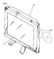
- FIG. 1 is a perspective view of a liquid crystal display device with a built-in disk device according to this embodiment
- FIG. 2 is a perspective view of the liquid crystal display device with a back cabinet removed
- FIG. 3 is a rear view thereof.
- the liquid crystal display device 10 with a built-in disk device (hereinafter simply referred to as "LCD 10") according to this embodiment is constructed of a disk device 11, a disk device control substrate 12, an LCD module (not shown), a main control substrate 14, a chassis 15, a speaker 16, etc., all of which are housed in a housing 17.
- the housing 17 is constructed of a front cabinet 17a and a back cabinet 17b. As shown in FIG. 2 and FIG.
- the disk device 11 and disk device control substrate 12 are arranged side by side and a flexible flat cable (hereinafter simply referred to as "FFC") 23 for transmitting a signal from a pickup section 11a provided for the disk device 11 to the disk device control substrate 12 is connected to the pickup section 11a and the disk device control substrate 12 through a slit 11b1 provided in a frame side 11b of the disk device 11.
- the outer frame of the disk device 11 is generally a resin frame.
- the disk device 11 is provided with the pickup section 11a, etc. , which moves to and fro in the radius direction of an optical disk medium 20 to read and/or write a signal from/to the optical disk medium 20 and the disk device control substrate 12 is a substrate which controls a drive motor, etc. , provided for the disk device 11 or controls a signal input/output to/from the pickup section 11a.
- An LCD module is provided with a liquid crystal panel 13 which is a display device, a liquid crystal panel drive circuit which controls and drives the liquid crystal panel, a backlight which is a light source and an inverter circuit which controls and drives the backlight, and the main control substrate 14 controls the LCD module and processes/controls, etc., a video/speech signal.
- the main control substrate 14 and disk device control substrate 12 are shown in a simplified form in the figure, but they have a structure including various electric/electronic parts mounted on a printed circuit board on which a circuit pattern is printed.
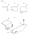
- FIG. 4 shows a stopper provided for the disk device control substrate 12 to retain the shape of the FFC 23, (a) is a side view of the stopper 40, (b) is a front view and (c) is a top view. (d) is a perspective view of the stopper 40 and shows how it is attached to the disk device control substrate 12. As shown in the figure, the stopper 40 is fixed together with the disk device control substrate 12 using a screw for attaching the disk device control substrate 12 to the chassis 15.
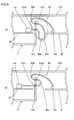
- FIG. 5 is a schematic view illustrating the routing of the FFC 23 which connects the disk device control substrate 12 provided with the stopper 40 to the pickup section 11a viewed from the direction indicated by an arrowed line B-B in FIG. 2.
- FIG. 5 (a) is a schematic view when the disk device control substrate 12 and pickup section 11a are located closest to each other.
- FIG. 5(b) is a schematic view when the two are located farthest from each other.
- the FFC 23 is provided with a slack portion 23a to absorb the moving distance of the pickup section 11a and the slack portion 23a is provided with a bending section 23b and a bending section 23c bent in mutually opposite curving directions, which causes the FFC 23 to have a substantially S-figure.
- the FFC 23 is stopped at the bending section 23b by the L-figured stopper 40.
- the movement of the slack portion 23a of the FFC 23 caused by reciprocating motion of the pickup section 11a is absorbed by the stopper 40 and bending section 23b and bending section 23c, which drastically prevents the influence of the movement of the pickup section 11a from transmitting to a connection 12a.
- the FFC 23 since there is substantially no movement of the cable from the bending section 23b to the connection 12a where the shape of the cable is retained by the stopper 40, the FFC 23 does not move while touching (rubbing against) the back cabinet 17b, which also prevents damage to the coating of the FFC 23. Furthermore, the range of movement of the portion of the FFC 23 which moves (especially the part close to the bending section 23c) is limited to within the space between the frame side 11b of the disk device 11 and the stopper 40, and therefore it is possible to prevent a problem that the FFC 23 may be hooked by other members inside the device.
- FIG. 6 is a perspective view showing a liquid crystal display device with a built-in disk device according to this embodiment with a back cabinet thereof removed
- FIG. 7 is a schematic view illustrating the routing of an FFC which connects a disk device control substrate and a pickup section provided for the disk device viewed from the direction indicated by an arrowed line C-C in FIG. 6.
- FIG. 7(a) is a schematic view when the disk device control substrate and pickup section are located closest to each other
- FIG. 7(b) is a schematic view when the two are located farthest from each other.
- the components similar to those in Embodiment 1 are assigned the same reference numerals as those in Embodiment 1 and explanations thereof will be omitted here.
- the FFC 73 is provided with a slack portion 73a to absorb the moving distance of a pickup section 11a and the slack portion 73a is provided with a bending section 73b and a bending section 73c bent in the same curving direction, which causes the FFC 73 to have substantially a spiral shape (the figure shows the bending section 73b and bending section 73c having different curvatures to make a clear distinction between the two, but the bending section 73b and bending section 73c may also have substantially the same curvature so that the bending section 73b and bending section 73c substantially form a continuous arc). As shown in FIG.
- the movement of the slack portion 73a of the FFC 73 produced by reciprocating motion of the pickup section 11a is absorbed by the bending section 73b and bending section 73c, and therefore a load on a connection 12a is reduced. Furthermore, since the FFC 73 does not swell toward the back cabinet 17b, it is possible to prevent the FFC 73 from touching the back cabinet 17b and make the LCD 70 as thin as possible. Moreover, implementing the present invention requires no additional member, which contributes to a cost reduction.
- a stopper such as a hook in the part of the disk device 11 where the side 11b almost contacts the FFC 73 (vicinity of the bending section 73b in FIG. 7) so as to stop the FFC 73.
- a stopper such as a hook in the part of the disk device 11 where the side 11b almost contacts the FFC 73 (vicinity of the bending section 73b in FIG. 7) so as to stop the FFC 73.
- Such a structure can further reduce the load on the connection 12a.
- FIG. 8 is perspective view of a liquid crystal display device with a built-in disk device according to this embodiment with a back cabinet thereof removed
- FIG. 9 is a schematic view illustrating the routing of an FFC which connects a disk device control substrate and a pickup section provided for the disk device viewed from the direction indicated by an arrowed line D-D in FIG. 8.
- FIG. 9(a) is a schematic view when the disk device control substrate and pickup section are located closest to each other
- FIG. 9(b) is a schematic view when the two are located farthest from each other.
- the components similar to those in Embodiment 1 are assigned the same reference numerals as those in Embodiment 1 and explanations thereof will be omitted here.
- the FFC 93 is provided with a slack portion 93a to absorb the moving distance of a pickup section 11a and the slack portion 93a is provided with a bending section 93b and a bending section 93c bent in mutually opposite curving directions, which causes the FFC 93 to become substantially a sigmoid curve.
- the FFC 93 is stopped by being passed through a slit 11b2 provided in a frame side 11b of a disk device 11 in the vicinity of the bending section 93b. As shown in FIG.
- the movement of the slack portion 93a of the FFC 93 caused by reciprocating motion of the pickup section 11a is absorbed by the frame side piece 11b of the disk device 11, bending section 93b and bending section 93c, and therefore a load on a connection 12a is reduced.
- Another structure of the stopping/retaining section which retains the shape of the FFC 93 may be formed by providing a hook 100 as shown in FIG. 10 in the frame side piece 11b of the disk device 11.
- FIG. 11 shows a stopper provided for a disk device control substrate for retaining the shape of an FFC
- FIG. 11(a) is a top perspective view
- (b) is a bottom perspective view
- (c) is a schematic view illustrating the routing of the FFC which connects the disk device control substrate and a pickup section provided for the disk device.
- FIG. 12 is a schematic view illustrating conditions of the stopper and the FFC inside the device when a load is applied from the outside to the back cabinet of the liquid crystal display device with a built-in disk device.
- the stopper 170 corresponds to the stopper 40 shown in Embodiment 1 with convex parts 171 formed at parts thereof through drawing.
- the convex parts 171 are formed at positions facing the top end (end of the frame side piece) of the frame side piece 11b of the disk device 11 in such a way as to exceed in height the thickness of the FFC 23.
- the convex parts 171 formed in the stopper 170 contact the top end of the frame side piece 11b preventing the FFC 23 from being caught between the stopper 170 and frame side piece 11b. This can prevent problems of causing an adverse influence on the operation of the pickup section 11a, imposing a load on each member connected to the FFC 23 and damaging the FFC 23 itself.
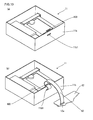
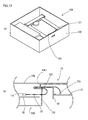
- FIG. 13(a) is a top perspective view of a disk device of this embodiment
- FIG. 13(b) is a schematic view illustrating the routing of an FFC which connects a disk device control substrate and a pickup section provided for the disk device
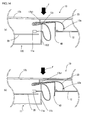
- FIG. 14 is a schematic view illustrating conditions of a stopper and FFC inside the device when a load is applied from the outside to a back cabinet of a liquid crystal display device incorporating this disk device.
- the basic structure of the liquid crystal display device with a built-in disk device of this embodiment is the same as that of Embodiment 1, and therefore the components similar to those in Embodiment 1 are assigned the same reference numerals as those in Embodiment 1 and explanations thereof will be omitted here.
- convex parts 131 are formed at the top end of a frame side piece 132 (end of the frame side piece) of the disk device 130 of this embodiment.
- the convex parts 131 are formed at positions facing a stopper 40 in such a way as to exceed in height the thickness of the FFC 23.
- the convex parts 131 formed at the top end of the frame side piece 132 contact the stopper 40, preventing the FFC 23 from being caught between the stopper 40 and frame side piece 132. This can prevent problems of causing an adverse influence on the operation of a pickup section 11a, imposing a load on each member connected to the FFC 23 and damaging the FFC 23 itself.
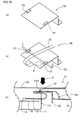
- FIG. 15 illustrates a stopper provided for a disk device control substrate to retain the shape of an FFC
- FIG. 15(a) is a top perspective view
- (b) and (c) are schematic views illustrating conditions of the stopper and FFC inside the device when a load is applied from the outside to a back cabinet of a liquid crystal display device with a built-in disk device.
- the basic structure of the liquid crystal display device with a built-in disk device of this embodiment is the same as that of Embodiment 1 except the stopper, and therefore the components similar to those in Embodiment 1 are assigned the same reference numerals as those in Embodiment 1 and explanations thereof will be omitted here.
- the stopper 150 of this embodiment corresponds to the stopper 40 shown in Embodiment 1 with convex parts 151 formed at parts thereof through drawing.
- the convex parts 151 are formed at positions facing a member 17b1 (protrusion) formed on the inner wall surface side of a back cabinet 17b in such a way as to exceed in height the thickness of the FFC 23.
- the back cabinet 17b When a load F is applied to the back cabinet 17b, the back cabinet 17b is bent in an inward direction of the device and the protrusion formed on the inner wall surface side of the back cabinet 17b contacts the stopper, if the protrusion contacts the stopper at a position other than the position where the FFC 23 is located (e.g. , part indicated by N in FIG.
- the FFC 23 is hardly caught between the protrusion formed on the inner wall surface side of the back cabinet 17b and stopper even when the back cabinet 17b is bent in an inward direction of the device, whereas if the protrusion contacts the stopper at the same position that the FFC 23 is located (e.g., the protrusion is a rib for reinforcing the cabinet and overlaps the position at which the FFC 23 is located as the member 17b1 shown in FIG. 15(b)), the FFC 23 may be caught between the protrusion formed on the inner wall surface side of the back cabinet 17b and the stopper.
- the stopper 150 of this embodiment as shown in FIG.
- the convex parts 151 formed in the stopper 150 contact the member 17b1 (protrusion) formed on the inner wall surface side of the back cabinet 17b, preventing the FFC 23 from being caught between the stopper 150 and back cabinet 17b. This can prevent a problem of damaging the FFC 23 (even when the FFC 23 is located between the stopper 150 and back cabinet 17b, this can hardly cause the operation of the pickup section 11a to be adversely affected).
- the convex parts 151 are formed only on the side facing the inner wall surface side of the back cabinet 17b, but in addition to this, it is also possible to form convex parts (convex parts 171 in Embodiment 4) on the side facing the frame side piece 11b or form convex parts (convex parts 131 in Embodiment 5) at the top end of the frame side piece 11b of the disk device (this would not be required when the stopper 150 is formed of a highly resistant member, which eliminates the necessity for taking into consideration a situation in which the stopper 150 is bent (that is, a situation in which the FFC 23 is caught between the stopper 150 and frame side piece 11b)).
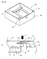
- FIG. 16(a) is a top perspective view of a disk device of this embodiment
- FIG. 16(b) is a schematic view illustrating conditions of a stopper and FFC inside the device when a load is applied from the outside to a back cabinet of the liquid crystal display device with a built-in disk device.
- the basic structure of the liquid crystal display device with a built-in disk device of this embodiment is the same as that of Embodiment 1, and therefore the components similar to those in Embodiment 1 are assigned the same reference numerals as those in Embodiment 1 and explanations thereof will be omitted here.
- convex parts 161 are formed at the top end of a frame side piece 162 (end of the frame side piece).
- the convex parts 161 are formed at positions not facing a stopper 40 in such a way as to exceed in height the thickness of an FFC 23 placed between the inner wall surface of a back cabinet 17b and the top end of the frame side piece 162 (corresponding to thickness of two FFCs 23 in this embodiment) and the thickness of the stopper 40.
- the convex parts 161 formed at the top end of the frame side piece 162 contact the innerwall surface side of the back cabinet 17b or a member 17b1 formed on the inner wall surface side of the back cabinet 17b, preventing the FFC 23 from being caught between the stopper 40 and frame side piece 162 or between the stopper 40 and back cabinet 17b.
- This can prevent problems of causing an adverse influence on the operation of a pickup section 11a, imposing a load on each member connected to the FFC 23 and damaging the FFC 23 itself.
- This embodiment assumes that the convex parts 161 are formed at the top end of the frame side piece 162 of the disk device, but it is also possible to form convex parts 161 on the inner wall surface side of the back cabinet 17b to produce similar effects.
Landscapes
- Engineering & Computer Science (AREA)
- Microelectronics & Electronic Packaging (AREA)
- Moving Of Heads (AREA)
- Insertion, Bundling And Securing Of Wires For Electric Apparatuses (AREA)
Applications Claiming Priority (4)
| Application Number | Priority Date | Filing Date | Title |
|---|---|---|---|
| JP2004176786 | 2004-06-15 | ||
| JP2004176786 | 2004-06-15 | ||
| JP2005030691A JP2006031910A (ja) | 2004-06-15 | 2005-02-07 | ディスク装置を内蔵した電子装置 |
| JP2005030691 | 2005-02-07 |
Publications (2)
| Publication Number | Publication Date |
|---|---|
| EP1607977A2 true EP1607977A2 (de) | 2005-12-21 |
| EP1607977A3 EP1607977A3 (de) | 2007-06-06 |
Family
ID=34941673
Family Applications (1)
| Application Number | Title | Priority Date | Filing Date |
|---|---|---|---|
| EP05253666A Withdrawn EP1607977A3 (de) | 2004-06-15 | 2005-06-14 | Elektronisces Gerät mit eingebauter Platteneinrichtung |
Country Status (3)
| Country | Link |
|---|---|
| US (1) | US20050289575A1 (de) |
| EP (1) | EP1607977A3 (de) |
| JP (1) | JP2006031910A (de) |
Cited By (2)
| Publication number | Priority date | Publication date | Assignee | Title |
|---|---|---|---|---|
| EP1577894A3 (de) * | 2004-03-19 | 2008-01-09 | ORION ELECTRIC CO., Ltd. | Flüssigkristall - Anzeigevorrichtung mit integrierter Plattenvorrichtung |
| EP2101330A1 (de) * | 2008-03-11 | 2009-09-16 | Funai Electric Co., Ltd. | Plattenvorrichtung |
Families Citing this family (6)
| Publication number | Priority date | Publication date | Assignee | Title |
|---|---|---|---|---|
| JP4356523B2 (ja) * | 2004-06-04 | 2009-11-04 | ソニー株式会社 | ディスクドライブ装置、ディスクドライブユニット、光学ピックアップ装置 |
| JP2009141241A (ja) | 2007-12-10 | 2009-06-25 | Funai Electric Co Ltd | フレキシブルフラットケーブルの配設構造 |
| JP2011086322A (ja) * | 2009-10-13 | 2011-04-28 | Funai Electric Co Ltd | 電気機器装置 |
| JP2012230742A (ja) * | 2011-04-27 | 2012-11-22 | Funai Electric Co Ltd | 光ディスク装置 |
| EP3125656B1 (de) * | 2014-03-26 | 2020-02-19 | Panasonic Intellectual Property Management Co., Ltd. | Elektronische vorrichtung und anzeigeeinheit |
| CN112788886B (zh) * | 2020-06-23 | 2023-06-02 | 北京可利尔福科技有限公司 | 摄像模组 |
Citations (3)
| Publication number | Priority date | Publication date | Assignee | Title |
|---|---|---|---|---|
| JP2001283497A (ja) | 2000-03-30 | 2001-10-12 | Pioneer Electronic Corp | ディスクプレーヤ |
| JP2002324389A (ja) | 2002-03-20 | 2002-11-08 | Teac Corp | ディスクドライブ装置 |
| JP2003100036A (ja) | 2001-09-25 | 2003-04-04 | Citizen Watch Co Ltd | 走査型ヘッド |
Family Cites Families (4)
| Publication number | Priority date | Publication date | Assignee | Title |
|---|---|---|---|---|
| JP3105620B2 (ja) * | 1992-03-16 | 2000-11-06 | オリンパス光学工業株式会社 | 光学式情報記録再生装置 |
| JPH10134412A (ja) * | 1996-10-30 | 1998-05-22 | Akai Electric Co Ltd | 記録または再生装置のピックアップ装置 |
| JPH10283703A (ja) * | 1997-04-02 | 1998-10-23 | Mitsumi Electric Co Ltd | ディスククランパ及び前記ディスククランパを備えたディスク駆動装置 |
| WO2003017279A1 (fr) * | 2001-08-16 | 2003-02-27 | Citizen Watch Co., Ltd. | Dispositif lecteur de disque |
-
2005
- 2005-02-07 JP JP2005030691A patent/JP2006031910A/ja active Pending
- 2005-06-14 US US11/151,458 patent/US20050289575A1/en not_active Abandoned
- 2005-06-14 EP EP05253666A patent/EP1607977A3/de not_active Withdrawn
Patent Citations (3)
| Publication number | Priority date | Publication date | Assignee | Title |
|---|---|---|---|---|
| JP2001283497A (ja) | 2000-03-30 | 2001-10-12 | Pioneer Electronic Corp | ディスクプレーヤ |
| JP2003100036A (ja) | 2001-09-25 | 2003-04-04 | Citizen Watch Co Ltd | 走査型ヘッド |
| JP2002324389A (ja) | 2002-03-20 | 2002-11-08 | Teac Corp | ディスクドライブ装置 |
Cited By (3)
| Publication number | Priority date | Publication date | Assignee | Title |
|---|---|---|---|---|
| EP1577894A3 (de) * | 2004-03-19 | 2008-01-09 | ORION ELECTRIC CO., Ltd. | Flüssigkristall - Anzeigevorrichtung mit integrierter Plattenvorrichtung |
| EP2101330A1 (de) * | 2008-03-11 | 2009-09-16 | Funai Electric Co., Ltd. | Plattenvorrichtung |
| US8151286B2 (en) | 2008-03-11 | 2012-04-03 | Funai Electric Co., Ltd. | Disk device |
Also Published As
| Publication number | Publication date |
|---|---|
| EP1607977A3 (de) | 2007-06-06 |
| JP2006031910A (ja) | 2006-02-02 |
| US20050289575A1 (en) | 2005-12-29 |
Similar Documents
| Publication | Publication Date | Title |
|---|---|---|
| US11966259B2 (en) | Electronic device including foldable display | |
| KR102862341B1 (ko) | 플렉서블 디스플레이를 포함하는 전자 장치 | |
| US20110024162A1 (en) | Flexible wiring unit and electronic apparatus | |
| US6806919B1 (en) | Liquid crystal display with coupled frame and method of fabricating the same | |
| EP1607977A2 (de) | Elektronisces Gerät mit eingebauter Platteneinrichtung | |
| JPWO2007119814A1 (ja) | 光伝送モジュール、接続部品、および光伝送モジュールを備えた電子機器 | |
| US9042109B2 (en) | Mounting structure of flexible printed circuit board and sliding-type electronic device | |
| US20250023966A1 (en) | Foldable electronic device including flexible printed circuit board | |
| US20240007555A1 (en) | Display device | |
| KR20230087781A (ko) | 디스플레이 장치 | |
| CN101854407B (zh) | 信息终端装置 | |
| US8639068B2 (en) | Optical transmission module, electronic instrument, method for assembling optical transmission module, and optical transmission method | |
| US8181190B2 (en) | Optical disc apparatus | |
| CN115620624B (zh) | 显示设备和包括该显示设备的可移动设备 | |
| US11507136B2 (en) | Electronic apparatus with frame including a glass support | |
| CN217825081U (zh) | 线路板组件、摄像模组及电子设备 | |
| US20070283370A1 (en) | Optical disc drive | |
| JP2010103356A (ja) | 電子装置、及びその製造方法 | |
| US6667853B2 (en) | Holding structure of indicating display device for recording medium drive, and recording medium drive | |
| US20230156984A1 (en) | Display apparatus | |
| KR100578351B1 (ko) | 플렉시블 케이블 | |
| JP2009266847A (ja) | フレキシブル配線ユニットおよび電子機器 | |
| JP2025009001A (ja) | 電子機器 | |
| KR20250170457A (ko) | 가이드 레일을 포함하는 전자 장치 | |
| KR20250093104A (ko) | 지지 플레이트를 포함하는 전자 장치 |
Legal Events
| Date | Code | Title | Description |
|---|---|---|---|
| PUAI | Public reference made under article 153(3) epc to a published international application that has entered the european phase |
Free format text: ORIGINAL CODE: 0009012 |
|
| AK | Designated contracting states |
Kind code of ref document: A2 Designated state(s): AT BE BG CH CY CZ DE DK EE ES FI FR GB GR HU IE IS IT LI LT LU MC NL PL PT RO SE SI SK TR |
|
| AX | Request for extension of the european patent |
Extension state: AL BA HR LV MK YU |
|
| PUAL | Search report despatched |
Free format text: ORIGINAL CODE: 0009013 |
|
| AK | Designated contracting states |
Kind code of ref document: A3 Designated state(s): AT BE BG CH CY CZ DE DK EE ES FI FR GB GR HU IE IS IT LI LT LU MC NL PL PT RO SE SI SK TR |
|
| AX | Request for extension of the european patent |
Extension state: AL BA HR LV MK YU |
|
| AKX | Designation fees paid | ||
| REG | Reference to a national code |
Ref country code: DE Ref legal event code: 8566 |
|
| STAA | Information on the status of an ep patent application or granted ep patent |
Free format text: STATUS: THE APPLICATION IS DEEMED TO BE WITHDRAWN |
|
| 18D | Application deemed to be withdrawn |
Effective date: 20071207 |