EP1608876B1 - Pompe de fluide refrigerant, en particulier, pompe electrique a refroidissement hydraulique, a distributeur integre, et procede correspondant - Google Patents
Pompe de fluide refrigerant, en particulier, pompe electrique a refroidissement hydraulique, a distributeur integre, et procede correspondant Download PDFInfo
- Publication number
- EP1608876B1 EP1608876B1 EP04718939A EP04718939A EP1608876B1 EP 1608876 B1 EP1608876 B1 EP 1608876B1 EP 04718939 A EP04718939 A EP 04718939A EP 04718939 A EP04718939 A EP 04718939A EP 1608876 B1 EP1608876 B1 EP 1608876B1
- Authority
- EP
- European Patent Office
- Prior art keywords
- pump
- coolant
- housing
- coolant pump
- bypass
- Prior art date
- Legal status (The legal status is an assumption and is not a legal conclusion. Google has not performed a legal analysis and makes no representation as to the accuracy of the status listed.)
- Expired - Lifetime
Links
- 239000002826 coolant Substances 0.000 title claims abstract description 290
- 238000000034 method Methods 0.000 title claims abstract description 10
- 238000002485 combustion reaction Methods 0.000 claims abstract description 15
- 230000002093 peripheral effect Effects 0.000 claims abstract 5
- 238000010438 heat treatment Methods 0.000 claims description 22
- 230000008859 change Effects 0.000 claims description 13
- 238000001816 cooling Methods 0.000 claims description 13
- 230000005540 biological transmission Effects 0.000 claims description 9
- 238000011144 upstream manufacturing Methods 0.000 claims description 8
- 230000001419 dependent effect Effects 0.000 claims description 6
- 238000002156 mixing Methods 0.000 claims description 4
- 230000002706 hydrostatic effect Effects 0.000 claims description 2
- 238000005304 joining Methods 0.000 claims description 2
- 239000000314 lubricant Substances 0.000 claims 1
- 230000008901 benefit Effects 0.000 description 15
- 239000000203 mixture Substances 0.000 description 12
- XEEYBQQBJWHFJM-UHFFFAOYSA-N Iron Chemical compound [Fe] XEEYBQQBJWHFJM-UHFFFAOYSA-N 0.000 description 10
- 238000007789 sealing Methods 0.000 description 7
- LYCAIKOWRPUZTN-UHFFFAOYSA-N Ethylene glycol Chemical compound OCCO LYCAIKOWRPUZTN-UHFFFAOYSA-N 0.000 description 6
- 230000033001 locomotion Effects 0.000 description 6
- 239000012528 membrane Substances 0.000 description 6
- 239000004033 plastic Substances 0.000 description 6
- 229920003023 plastic Polymers 0.000 description 6
- 238000013461 design Methods 0.000 description 5
- 229910052742 iron Inorganic materials 0.000 description 5
- 239000000446 fuel Substances 0.000 description 4
- 238000004519 manufacturing process Methods 0.000 description 4
- 229910052751 metal Inorganic materials 0.000 description 4
- 239000002184 metal Substances 0.000 description 4
- XLYOFNOQVPJJNP-UHFFFAOYSA-N water Substances O XLYOFNOQVPJJNP-UHFFFAOYSA-N 0.000 description 4
- 230000034994 death Effects 0.000 description 3
- 238000006073 displacement reaction Methods 0.000 description 3
- WGCNASOHLSPBMP-UHFFFAOYSA-N hydroxyacetaldehyde Natural products OCC=O WGCNASOHLSPBMP-UHFFFAOYSA-N 0.000 description 3
- 239000010687 lubricating oil Substances 0.000 description 3
- 238000002844 melting Methods 0.000 description 3
- 230000008018 melting Effects 0.000 description 3
- 239000003921 oil Substances 0.000 description 3
- 238000013021 overheating Methods 0.000 description 3
- 238000005086 pumping Methods 0.000 description 3
- 238000003860 storage Methods 0.000 description 3
- 238000010276 construction Methods 0.000 description 2
- 238000011161 development Methods 0.000 description 2
- 230000018109 developmental process Effects 0.000 description 2
- 238000009826 distribution Methods 0.000 description 2
- 229920001971 elastomer Polymers 0.000 description 2
- 239000000806 elastomer Substances 0.000 description 2
- 238000005516 engineering process Methods 0.000 description 2
- 230000002349 favourable effect Effects 0.000 description 2
- 230000017525 heat dissipation Effects 0.000 description 2
- 230000008569 process Effects 0.000 description 2
- 230000009467 reduction Effects 0.000 description 2
- 239000000243 solution Substances 0.000 description 2
- 230000001133 acceleration Effects 0.000 description 1
- 230000009471 action Effects 0.000 description 1
- 229910052782 aluminium Inorganic materials 0.000 description 1
- XAGFODPZIPBFFR-UHFFFAOYSA-N aluminium Chemical compound [Al] XAGFODPZIPBFFR-UHFFFAOYSA-N 0.000 description 1
- 230000004888 barrier function Effects 0.000 description 1
- 230000033228 biological regulation Effects 0.000 description 1
- 239000000919 ceramic Substances 0.000 description 1
- 230000000295 complement effect Effects 0.000 description 1
- 230000007547 defect Effects 0.000 description 1
- 238000001514 detection method Methods 0.000 description 1
- 238000010586 diagram Methods 0.000 description 1
- 230000009977 dual effect Effects 0.000 description 1
- 230000000694 effects Effects 0.000 description 1
- 210000003746 feather Anatomy 0.000 description 1
- 238000007654 immersion Methods 0.000 description 1
- 238000001746 injection moulding Methods 0.000 description 1
- 238000009434 installation Methods 0.000 description 1
- 238000011835 investigation Methods 0.000 description 1
- 239000007788 liquid Substances 0.000 description 1
- 230000007774 longterm Effects 0.000 description 1
- 239000000463 material Substances 0.000 description 1
- 230000002503 metabolic effect Effects 0.000 description 1
- 238000012986 modification Methods 0.000 description 1
- 230000004048 modification Effects 0.000 description 1
- 239000010705 motor oil Substances 0.000 description 1
- 229910000510 noble metal Inorganic materials 0.000 description 1
- 230000008092 positive effect Effects 0.000 description 1
- 238000012805 post-processing Methods 0.000 description 1
- 230000035484 reaction time Effects 0.000 description 1
- 230000001105 regulatory effect Effects 0.000 description 1
- 238000012360 testing method Methods 0.000 description 1
- 238000012546 transfer Methods 0.000 description 1
- 239000002918 waste heat Substances 0.000 description 1
Images






Classifications
-
- F—MECHANICAL ENGINEERING; LIGHTING; HEATING; WEAPONS; BLASTING
- F04—POSITIVE - DISPLACEMENT MACHINES FOR LIQUIDS; PUMPS FOR LIQUIDS OR ELASTIC FLUIDS
- F04D—NON-POSITIVE-DISPLACEMENT PUMPS
- F04D29/00—Details, component parts, or accessories
- F04D29/40—Casings; Connections of working fluid
- F04D29/42—Casings; Connections of working fluid for radial or helico-centrifugal pumps
- F04D29/426—Casings; Connections of working fluid for radial or helico-centrifugal pumps especially adapted for liquid pumps
-
- F—MECHANICAL ENGINEERING; LIGHTING; HEATING; WEAPONS; BLASTING
- F01—MACHINES OR ENGINES IN GENERAL; ENGINE PLANTS IN GENERAL; STEAM ENGINES
- F01P—COOLING OF MACHINES OR ENGINES IN GENERAL; COOLING OF INTERNAL-COMBUSTION ENGINES
- F01P5/00—Pumping cooling-air or liquid coolants
- F01P5/10—Pumping liquid coolant; Arrangements of coolant pumps
-
- F—MECHANICAL ENGINEERING; LIGHTING; HEATING; WEAPONS; BLASTING
- F01—MACHINES OR ENGINES IN GENERAL; ENGINE PLANTS IN GENERAL; STEAM ENGINES
- F01P—COOLING OF MACHINES OR ENGINES IN GENERAL; COOLING OF INTERNAL-COMBUSTION ENGINES
- F01P7/00—Controlling of coolant flow
- F01P7/14—Controlling of coolant flow the coolant being liquid
- F01P7/16—Controlling of coolant flow the coolant being liquid by thermostatic control
-
- F—MECHANICAL ENGINEERING; LIGHTING; HEATING; WEAPONS; BLASTING
- F04—POSITIVE - DISPLACEMENT MACHINES FOR LIQUIDS; PUMPS FOR LIQUIDS OR ELASTIC FLUIDS
- F04D—NON-POSITIVE-DISPLACEMENT PUMPS
- F04D13/00—Pumping installations or systems
- F04D13/02—Units comprising pumps and their driving means
- F04D13/06—Units comprising pumps and their driving means the pump being electrically driven
-
- F—MECHANICAL ENGINEERING; LIGHTING; HEATING; WEAPONS; BLASTING
- F04—POSITIVE - DISPLACEMENT MACHINES FOR LIQUIDS; PUMPS FOR LIQUIDS OR ELASTIC FLUIDS
- F04D—NON-POSITIVE-DISPLACEMENT PUMPS
- F04D15/00—Control, e.g. regulation, of pumps, pumping installations or systems
- F04D15/0005—Control, e.g. regulation, of pumps, pumping installations or systems by using valves
- F04D15/0016—Control, e.g. regulation, of pumps, pumping installations or systems by using valves mixing-reversing- or deviation valves
-
- F—MECHANICAL ENGINEERING; LIGHTING; HEATING; WEAPONS; BLASTING
- F04—POSITIVE - DISPLACEMENT MACHINES FOR LIQUIDS; PUMPS FOR LIQUIDS OR ELASTIC FLUIDS
- F04D—NON-POSITIVE-DISPLACEMENT PUMPS
- F04D29/00—Details, component parts, or accessories
- F04D29/58—Cooling; Heating; Diminishing heat transfer
- F04D29/5806—Cooling the drive system
-
- F—MECHANICAL ENGINEERING; LIGHTING; HEATING; WEAPONS; BLASTING
- F01—MACHINES OR ENGINES IN GENERAL; ENGINE PLANTS IN GENERAL; STEAM ENGINES
- F01P—COOLING OF MACHINES OR ENGINES IN GENERAL; COOLING OF INTERNAL-COMBUSTION ENGINES
- F01P7/00—Controlling of coolant flow
- F01P7/14—Controlling of coolant flow the coolant being liquid
- F01P2007/146—Controlling of coolant flow the coolant being liquid using valves
-
- F—MECHANICAL ENGINEERING; LIGHTING; HEATING; WEAPONS; BLASTING
- F05—INDEXING SCHEMES RELATING TO ENGINES OR PUMPS IN VARIOUS SUBCLASSES OF CLASSES F01-F04
- F05D—INDEXING SCHEME FOR ASPECTS RELATING TO NON-POSITIVE-DISPLACEMENT MACHINES OR ENGINES, GAS-TURBINES OR JET-PROPULSION PLANTS
- F05D2270/00—Control
- F05D2270/60—Control system actuates means
- F05D2270/62—Electrical actuators
Definitions
- the present invention relates to a coolant pump according to the preamble of claim 1, and a method for this according to the preamble of claim 22.
- thermal management refers to those measures that lead to the energetically and thermo-mechanically optimal operation of an internal combustion engine. For this purpose, an active control of the heat flows and thus the temperature distribution in the engine is required.
- coolant pumps are increasingly used instead of the conventional, rigidly coupled to the engine speed coolant pumps whose speed is variable and thus the flow rate is adjustable.
- the discussed there electrical coolant pump with integrated directional control valve has a coolant pump housing, which has a suction nozzle for the inlet from the radiator, a bypass nozzle for the inlet of the bypass circuit and a discharge nozzle for the supply or return of the coolant to the vehicle engine.
- a coolant pump electric motor is arranged, the motor housing is flowed around by the circulated coolant.
- the pump motor drives a pump impeller via a pump shaft to circulate the coolant.
- Suction nozzle and bypass nozzle upstream of the integrated in the coolant pump directional control valve in the inlet to the pump are integrated so that when open directional control valve, a mixture of cooler coolant coming from the radiator and directly coming from the motor vehicle heated coolant sucked by the pump impeller and the pump motor over to the downstream pressure nozzle for the supply or return of this coolant mixture to the motor vehicle engine.
- the maximum temperature of the cooled by the radiator pending at the output and from there to the pump coolant flowing 113 ° C.
- This desired upper value has been set by the automotive industry for the design of automotive radiators. This is to ensure that when operating a motor vehicle, even in extremely hot areas, such as in the desert, cooled coolant for the motor vehicle engine is available in a temperature range available with a maximum Input temperature of 113 ° C supplied to the engine, with a remaining temperature range of at least 7 ° C to 17 ° C to a maximum allowed for conventional coolant upper limit of 120 ° C to at most 130 ° C still sufficient heat from the engine and take to the radiator can dissipate.
- the temperature of the coolant carried away from the engine can easily reach 120 ° C or, in unfavorable cases, more, ie up to 130 ° C.
- a short circuit or bypass circuit can be returned to the heated coolant from the engine coming via the coolant pump directly to the engine.
- the Anürmphase the engine shortened overall, achieved a rapid warm-up of the cylinder tube after the cold start and a control of the tribologically optimum temperature are possible.
- the coolant pump installed electronic as well as electrical components such as the electric motor that drives the pump impeller or the electronic components, sensors, transducers or control loops that allow control and / or regulation of the engine speed, the pump power, the valve position or other functions point a limited temperature compatibility and are therefore not infinitely high temperatures exposable.
- electrical components such as the electric motor that drives the pump impeller or the electronic components, sensors, transducers or control loops that allow control and / or regulation of the engine speed, the pump power, the valve position or other functions point a limited temperature compatibility and are therefore not infinitely high temperatures exposable.
- components can be operated in some cases only a maximum of 120 ° C. Above threatens the rapid heat death of such electrical and / or electronic components.
- the newly proposed coolant pump for a coolant circuit of a motor vehicle internal combustion engine which has at least one radiator circuit and a bypass circuit, has a coolant pump housing having a suction port for the inlet from the radiator, a bypass port for the inlet of the bypass circuit and a pressure port for having the supply of the coolant from the motor vehicle engine.
- the coolant pump has a coolant pump housing arranged in the coolant pump housing, the motor housing flows around the coolant is, and drives a pump impeller via a pump shaft.
- the coolant pump has a directional control valve integrated in the coolant pump housing.
- the suction nozzle is arranged in the region of the pump impeller facing away from the end of the pump motor. Furthermore, it is proposed for the first time that the bypass nozzle is arranged in a region downstream of the suction nozzle, in particular after the pump motor.
- the discharge nozzle in a region lying downstream of the bypass nozzle, in particular after or in an area around the pump impeller, is arranged, finally, it is proposed for the first time that only the coolant, which through the suction nozzle for the inlet directly from Cooler can be sucked, in a sheath flow - by a, preferably from the outer wall of the pump motor housing and the facing inner wall of the pump housing and / or the facing inner wall of the directional valve limited flow channel - is fed past the pump motor, so that this and the other electronic and / or or electrical components can be optimally cooled.
- the direction of flow through the pump is reversed for the first time, ie the cooled coolant coming from the radiator, in particular a liquid coolant based on water, is supplied to the pump from the rear, so to speak.
- the cold, coming from the radiator coolant first flows past the pump motor, absorbs its waste heat and cools it down to allowable operating temperatures that are easily tolerated by the electric motor, before coming from the radiator coolant optionally with the supplied from the bypass circuit hot coolant mixed and this coolant mixture accelerated by the pump impeller or circulated through the discharge port to the vehicle engine off or is returned.
- the coolant pump according to the invention is also distinguished by its improved robustness, an extended field of application and significantly reduced production costs.
- the flow or coolant-cooled electric coolant pump according to the invention is an inexpensive and particularly reliable alternative to known solutions on the market.
- the coolant coming from the radiator circuit can be mixed with the coolant of the bypass circuit that can be sucked in by the bypass stub after the pump motor through the directional control valve.
- openable with the directional control valve and re-closable mouth of the bypass nozzle in an area upstream of the pump impeller is arranged so that the coolant mixture coming from the radiator cooled coolant and coming from the bypass heated coolant is accelerated or circulated together by the pump impeller can.
- the mouth of the directional control valve is located in a region between the pump impeller and the downstream end of the flow channel.
- the pump motor and the pump shaft are arranged coaxially to the longitudinal axis of the pump housing.
- the pump shaft is arranged coaxially to the longitudinal axis of the pump motor, however, this assembly is arranged asymmetrically or eccentrically in the pump housing, which may possibly lead to cost advantages in the manufacture of the housing.
- the concentric or coaxial variant is preferred because it builds much easier, due to the symmetries structurally easier to implement and fluidically provides the greatest benefits as well as probably the most cost-effective solution in terms of cost.
- the flow channel which is bounded by the outer wall of the motor housing comprising the pump motor and the facing inner wall of the pump housing, has an annular cross section.
- the flow channel has a constant cross section in the flow direction.
- a constriction of the prevailing at the end of the flow channel diameter to the diameter of the discharge nozzle is specified.
- the cooler with the Coolant pump sucked cool coolant can flow past without any loss of flow at constant cross section of the pump motor, this optimally cool and then sucked through the constriction at the end of the flow channel, sucked by the pump impeller or fed to the discharge nozzle, thereby simultaneously through the constriction of a bundling of total volume flow to the pump impeller takes place and also takes place a fluidic acceleration of the coolant.
- pressure losses are avoided in an advantageous manner and unwanted turbulence is excluded.
- the directional control valve is continuously switchable from a closed position "Bypass-closed” to an open position "Bypass-open".
- the directional control valve is designed as a valve slide which is displaceable in the longitudinal direction of the coolant pump.
- the valve slide is designed as a cylindrical sleeve. This can be made for example of metal.
- plastics can be used, for example also be used for the production ofméstoffpumperigephinuses.
- the coolant pump housing as the valve spool can be made particularly low, for example, in the plastic injection molding process. A reworking of these components is not necessary in an advantageous manner.
- valve spool valve has the further advantage of a fail-safe position, so that the radiator access in case of failure of the valve is open in any case.
- it is characterized by the lowest possible, ideally going to zero differential pressure. At the valve spool thus continues to occur advantageously no pressure drop, which ultimately leads to the fact that for switching or actuation of the valve already meets a very low switching capacity.
- valve spool Another advantage of the valve spool is that it can be formed without any leakage. In contrast, leakage is never completely ruled out with rotary valves due to the moving transversely to the main flow direction parts.
- the coolant pump according to the invention has the further advantage that a low pumping capacity already to achieve a desired Coolant flow rate is sufficient.
- This pump motors can be used with a low electrical power consumption.
- the coolant pump according to the invention has the further advantage that occurs in the valve position "radiator open" no reduction of the maximum flow cross-section, so that even for this reason a low flow rate for the circulation of the coolant is sufficient, so that the electric pump therefore also with an im Compared to commercial electric pumps lower power consumption can be produced.
- valve spool is actuated by an actuator, such as an electric actuating magnet, a Dehnscherlement, a hydrostatic pressure element or the like, displaced by force.
- an actuator such as an electric actuating magnet, a Dehnscherlement, a hydrostatic pressure element or the like, displaced by force.
- Such actuators are characterized by a very low tendency to wear, offer a long service life and particularly high switching cycles and are available at low cost. In addition, such actuators work extremely reliable and are largely throsunan Meeting.
- valve spool has a radially inwardly directed seal in the region of the supply of the coolant introduced from the bypass loop through the bypass spigot, which in the closed state of the directional control valve its mouth by a valve seat sealing against an annular sealing seat of the pump housing closes.
- the seal may be, for example, an elastomeric seal.
- the ring-shaped seat support guarantees an absolutely tight closing. Secondary leaks are excluded. A constriction of the distribution paths, regardless of whether the directional control valve is now in the position "Bypass closed” or in the position "Bypass open” is excluded, even in intermediate positions. This is a special streamlined valve variant specified.
- a cylindrical sleeve can be particularly easily sealed in a cylindrical housing, so that secondary leaks are excluded for this reason.
- Another advantage of the formed as a cylindrical sleeve valve slide is its relatively simple kinematics, so that a switching movement in the longitudinal direction is easily implemented.
- This offers the further advantage that a continuous mixture of bypass and inlet by a simple linear movement, namely a longitudinal displacement is realized, so that a direct, in particular linear, relationship between valve position or orifice and mixing ratio and current position of the valve spool consists Accordingly, control technology can be displayed easily or without special effort.
- the radially inwardly facing surface of the seal has a contour corresponding to the opposite contour of the motor housing.
- the solenoid actuating magnet of the valve slide has an armature which is formed by the cylindrical sleeve of the valve slide.
- the valve spool is used twice in an advantageous manner. On the one hand it is part of the valve and on the other hand it is at the same time a component of the solenoid solenoid. This helps to further reduce costs and increases reliability due to the reduced variety of parts. In this case, this dual function can be provided particularly favorable by a metal valve slide valve.
- an in Plastic executed valve spool area also have metallic sections that serve as anchors.
- the electric actuating magnet has a coil carrier arranged in the pump housing, which encloses the armature.
- the anchor formed by the valve sleeve can be completely enclosed by the coil carrier.
- the bobbin can thus optimally interact with the armature and move it already with low magnetic forces, so that so that the valve sleeve in the longitudinal direction relative to conventional valves can be relatively easily moved back and forth.
- the cylindrical valve sleeve can be guided sealed radially outward against the magnet with rod seals or the like, so that even at this point no secondary leakage can occur.
- a return for example, a heating circuit, a transmission oil heat exchanger, a lubricating oil heat exchanger, a separate cylinder block cooling circuit or the like, opens into the pump housing.
- the coolant circuit and the engine thermal management complementary secondary circuits can be detected by the electric coolant pump according to the invention and the coolant flowing there are supported by the coolant pump in an advantageous manner.
- a return can be coupled without a valve directly to the pump housing or, if necessary, have a valve for its targeted control, in which case advantageously the above-discussed directional control valve can be used in an adapted form.
- the pump housing is constructed in two parts. This allows a simplified construction of the electric coolant pump. Their assembly is facilitated. It is provided in a further preferred embodiment that the electric actuating magnet in the longitudinal direction oriented coil contacts, which in an advantageous manner when joining the two housing parts via correlating contacts with a housed in the other housing part control device, such as a CPU, a control unit or the like, can be brought into contact. This additionally facilitates the assembly.
- the coolant pump can be driven primarily mechanically via a lying outside of the pump housing pulley or the like.
- the pulley is decoupled via a freewheel from the pump shaft drive technology.
- a low-cost motor can take over the pump drive at a constant speed.
- the pulley then overtakes the electric motor.
- This also has the advantage that even in on-board networks with low electrical power, the coolant pump according to the invention can be used. This alternative is much cheaper than the expensive brushless drive motors. Ensuring the required basal metabolic pumping power is thus ensured even in case of failure of the electric motor.
- the directional control valve or its valve slide with a Dehnscherlelement is hydraulically driven or switched.
- the expansion element is designed, for example, as a wax element whose volume change due to a change in prevailing in the passing coolant temperature to a volume change in an adjacent, separate transmission medium, for example, also usable as a coolant water / glycol mixture leads.
- This separate transmission medium is separated from the wax element, for example by a flexible membrane.
- the volume change in the transmission medium is transmitted via corresponding lines, connecting holes or connecting channels to a cylinder space of the valve spool, so that it can be hydraulically actuated.
- a restoring force can be applied to the valve spool with a spring or the like.
- the expansion element is formed from wax. Its melting point is around 85 ° C. Its temperature-dependent volume change can then be transmitted via a separate coolant and associated connecting lines to the hydraulically driven valve spool.
- the expansion element formed from wax should be arranged in an area adjacent to the pressure port in the pump housing.
- it can adjoin the coolant flowing past by means of a metallic inner wall which is arranged radially inside the expansion element and which, for example, can be designed as a metallic cylinder jacket.
- the expansion element may be separated from the associated, separate coolant with a membrane arranged radially outside of it, such that a temperature-dependent volume change of the expansion element is transferable to the coolant.
- the separate coolant can in turn be moved over the connecting lines in a cylinder chamber of the thus hydraulically driven valve spool.
- a method for conveying coolant with a coolant pump for a coolant circuit of an automotive internal combustion engine having at least one radiator circuit and a bypass circuit comprises the following steps: a) supplying the coolant from the radiator to the coolant pump through a suction port of the coolant pump housing, b) supplying the coolant from the bypass circuit to the coolant pump through a bypass port, c) returning the coolant from the coolant pump to the vehicle engine by a pressure port, d) circulating the coolant with a pump impeller driven by a coolant pump electric motor via a pump shaft, the motor flowing around the coolant, e) adjusting the mixing ratio of the coolant flows circulating through the coolant pump with a directional control valve integrated in the coolant pump housing.
- the temperature detection of the mixed coolant takes place in the pump housing outlet leading to the motor vehicle engine, that is to say in the region of the discharge nozzle. This ensures that the motor vehicle engine is always supplied with a sufficient amount of coolant in the required temperature.
- the amount and temperature of the coolant which flows through the discharge nozzle to the engine depending on the temperature and amount of supplied by the bypass hot coolant, supplied by the inlet supplied by the radiator coolant, the amount of heat entered by the electric motor and, if necessary, a heating return or another return, such as supplied by a lubricating oil heat exchanger or a cylinder block cooling circuit heated further coolant.
- the CPU or control unit of the pump can deliver commands or voltage signals to the bobbin and the pump motor, so that the desired or required valve position is continuously adjusted and a requested engine speed is recorded.
- a correspondingly miniaturized or adapted variant of the slide valve can be used to control the return of a heater, a transmission oil heat exchanger or the like.
- the coolant pump housing is expanded by the valve function.
- the functionality of the coolant pump is increased and at the same time reduces the design effort, resulting in less effort during assembly and ultimately at a lower price.
- the split design of the housing also helps to reduce costs, since due to the housing division simpler assembly of the individual components is possible.
- the pump impeller arranged downstream of the pump motor on the pump shaft in the flow direction has, for example, an impeller and a stator.
- the principle used here corresponds to the already proven principle of the axial pump, as it is successfully sold in the house of the applicant.
- the required, narrow running gap is processed in one setting, so that the necessary accuracy is ensured and post-processing is eliminated.
- the control of the coolant pump according to the invention is designed so that even with a closed coolant circuit, ie at an open bypass circuit, no overheating of the electric motor threatens.
- the cooled coolant coming from the radiator is in the valve position "Bypass open” and "Radiator inlet closed” to the downstream end of the pump motor housing and encloses the pump motor or its housing.
- the coolant can still absorb a temperature interval of at least 7 ° C. of heat even in the worst case, until 120 ° C. has been reached and there is a threat of heat death of components.
- the control unit of the pump ensures that this case can not occur.
- the control unit ensures that the valve is briefly transferred to a position "inlet from the radiator open” and "by-pass closed”, briefly the pending coolant flows and then the valve is returned to its original position, so that then again fresh, completely cooled down coolant from the radiator encloses the electric pump and cools. Accordingly, even with a cold start and while doing some time switch position "bypass open", which is chosen to keep the warm-up phase of the vehicle internal combustion engine as short as possible, no risk to the electronic components to be feared.
- the slide seat valve can be adjusted continuously. There are no movement gaps that would be difficult to seal.
- the sealing ring which may be an elastomeric sealing ring, for example, lies axially against the seal seat of the housing in the "bypass closed” position. Accordingly, the elastomer sealing ring sets in a reverse manner at a position "inlet closed by the radiator” against the housing of the electric motor sealingly. Movement gaps do not exist. Secondary leaks are excluded.
- the solenoid is mounted opposite the valve sleeve with rod seals with Abstreiffunktion. This also excludes secondary leaks.
- valve sleeve for example, spring biased or applied with alternative means with a basic force, so that in the case of a defect in the electronics, the valve automatically in a position "inlet from the radiator open” and "Bypass closed” passes. This ensures a fail-safe position, which ensures that the motor vehicle engine can not overheat.
- the housing of the pump motor can be made of metal, for example of aluminum or another noble metal, which is particularly good heat-conducting. This ensures optimum heat dissipation from the electrically operated pump motor to the coolant flowing around it.
- bypass and the heating return in the non-temperature-critical region are supplied radially or tangentially from the outside to the pump center.
- Fig. 1 an exemplary assignment of circuits circuit diagram in a motor vehicle engine thermal management with the above-discussed coolant pump is shown in a simplified schematic representation.
- the electric coolant pump 1 is integrated in a coolant circuit 2.
- the coolant circuit 2 has a cooler circuit 4, which runs over a cooler 6.
- the coolant circuit 2 has a short circuit or bypass circuit 8, which closes the motor 10 directly to the coolant pump 1 short.
- a heating circuit 12 from the engine 10 via a heater 13 to the electric coolant pump 1 back to the engine 10 is shown.
- Other secondary circuits such as a coolant secondary circuit for a transmission oil heat exchanger for a lubricating oil heat exchanger, a separate cylinder head and a separate engine block cycle or the like are conceivable, but not shown here.
- the electric coolant pump 1 with integrated directional control valve conveys the coolant sucked in by the engine 10 in the cooler circuit 4 via the radiator 6 back to the engine 10 or circulates it. Further, the coolant pump 1 promotes the circulating in the short-circuit 8 coolant. Last but not least, the coolant pump 1 also circulates the circulating coolant in the heating circuit 12.
- the electrical coolant pump 1 with integrated directional control valve shown schematically in FIG. 1 with a symbol is explained in further detail in FIGS. 2 to 8 in various variants.
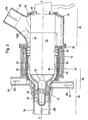
- FIG. 2 shows a first exemplary embodiment of a coolant pump 1 in longitudinal section.
- the coolant pump housing 14 is divided into two in this embodiment. It consists of a first housing part 16 and a second housing part 18. Both housing parts 16 and 18 with an annular clip, clamp or clamp 20 firmly together, tightly connected.
- the housing 14 can also be made in three or more parts or even in one piece with a lid.
- the coolant KZK coming from the cooler 6 in the cooler circuit 4 is fed to the pump housing 14 via the suction nozzle 22. This is symbolized by the arrow ZK pointing from the cooler 6 to the pump housing 14.
- a coolant pump electric motor 26 is arranged in the coolant pump housing 14. Whose motor housing 28 is flowed around to cool the electric motor 26 from flowing past coolant.
- the pump motor 26 drives a pump impeller 32 via a pump shaft 30.
- the pump impeller 32, the pump shaft 30 and the pump motor 26 are arranged coaxially with the longitudinal axis X of the pump housing 14.
- the coolant accelerated or circulated by the pump impeller 32 is conveyed away through a discharge nozzle 34 for the supply ZM of the coolant to the motor vehicle engine 10 symbolized with a further arrow.
- the coolant pump 1 in addition to the impeller 32 on a likewise arranged in the discharge nozzle 34 stator 36.
- a heating return 38 is shown, through which the supply ZH of the coolant from the heating circuit 12, symbolized in turn by an arrow, is possible for its circulation by the pump 1.
- a continuously adjustable directional control valve 40 is integrated in the coolant pump housing 14.
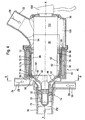
- the directional control valve can assume the position “bypass closed” or “supply from the radiator open” shown here in FIG. It can steplessly from this position on a position “bypass partially open” and “supply from the radiator partially open” (see Fig. 3) to a position “bypass open” or “supply from the radiator closed” (see FIG 4) and returned.
- the suction nozzle 22 is arranged in an upstream region 42, which is located in the region of the end remote from the pump impeller 32 end 44 of the pump motor 26.
- the bypass nozzle 24 is further arranged in a region 46 located downstream of the suction nozzle 22.
- the discharge nozzle 34 is arranged in a region 48 located downstream of the bypass nozzle 24.
- the jacket flow 50 is thereby bounded firstly on the one hand by the outer wall 52 of the pump motor housing 28 and on the other hand by the facing inner wall 54 of the pump housing 14 to form a flow channel 56.
- the flow channel 56 is then radially outwardly through the outer wall 52 of the pump motor housing 28 facing inner wall or inner surface 60 of the directional valve 40 is limited, which adjoins the housing inner wall 54 in the flow direction in the region of the connection point of the two housing parts 16 and 18.
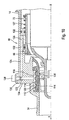
- FIG. 2 The exemplary embodiment of a flow-cooled electric coolant pump 1 with integrated directional control valve 40 shown in longitudinal section in FIG. 2 is again shown in longitudinal section in FIGS. 3 and 4, FIG. 3 showing a partially open position of the directional control valve 40 and FIG Directional valve 40 shows in which the inlet of the radiator ZK closed and the inlet of the bypass ZB is fully open.
- the mouth 62 is located between the pump impeller 32 and between the heating return 38 and the downstream end 64 of the flow channel 56th
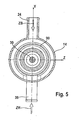
- the inlet ZB from the bypass circuit 8 and the inlet ZH from the heating circuit 12 are arranged in the same plane, coaxial to the Y-axis, opposite to the longitudinal axis X extending perpendicular to the image plane.
- the corresponding nozzle can also be connected tangentially to the housing 14. This is primarily dependent on the available in the engine compartment for the pump 1 installation space and the position of the inlets and outlets.
- the flow channel 56 delimited by the inner wall 54 of the pump housing 14 and / or by the inner wall 60 of the directional valve 40 on the one hand and on the other hand by the outer wall 52 of the pump motor 26 is annular in a particularly preferred embodiment or has an annular cross section.
- a motor housing 28 annularly enclosing sheath flow 56 is defined, which flows past the pump motor 26 and this optimally cools.
- the flow channel 56 has a cross section 66 which is constant in the flow direction. From the downstream end 64 of the flow channel 56 and from the downstream end 68 of the pump motor 26 to the pump impeller 32 is a continuous or continuous constriction of the prevailing at the end of the flow channel 56 diameter up to the inner diameter 70 of the discharge nozzle 34th
- the directional control valve 40 is designed as a valve slide 72, which is displaceable in the longitudinal direction X of the coolant pump 1 and, in the variant represented here, is configured as a cylindrical sleeve.
- the valve spool 72 is biased by a spring 73 or other suitable force-generating element so that in the event of valve control failure, the directional valve 40 is automatically transferred by the spring force of the spring 73 to a fail-safe position "inlet from the radiator open".
- the valve spool 72 is used in addition to its valve function at the same time as an armature 74 of the valve spool 72 actuated Elektrostellmagneten 76.
- the valve spool 72 is on its radially outer side by means of Rod seals 77 with Abstreiffunktion performed and against the housing. 14 or sealed against the other adjacent components.
- the solenoid actuator 76 has the aforementioned armature 74 and a coil support 78 arranged in the pump housing 14, which surrounds the armature 74.
- the armature 74 is formed in the manner of the cylindrical sleeve 72, that it is made of metal.
- the sleeve 72 can also be made of plastic and have the armature 74 forming metallic sections.
- the coil 80 is in turn surrounded by a radially outwardly of the coil 80 arranged iron yoke 82.
- Radial inside is an arranged between the coil support 78 and the armature 74, annular trained further iron yoke 84 integrated with characteristic influencing.
- the rod seals 77 are also arranged between the coil carrier 78 and the valve slide 72 formed as an armature 74, wherein a rod seal 77 connects directly to the iron yoke 84.
- the valve spool 72 has a radially inwardly directed seal 86 in the region of the bypass nozzle 24.
- the seal 86 may be formed as an elastomeric seal. Other seal materials are also usable.
- the seal 86 closes in a closed position "Bypass closed" of the directional control valve 40 with its annular flat face 88, the surface normal parallel to the longitudinal axis X, sealingly seals against a correspondingly formed annular seal seat 90 of the pump housing 14.
- the electric actuating magnet 76 has coil contacts 96 oriented in the longitudinal direction X or parallel to the X-axis. These coil contacts 96 correlate with corresponding contacts 98 of an integrated electronic component in the housing part 18, such as a control device 100, a CPU or the like, so that the control device 100 and the Elektrostellmagnet 76 directly during assembly of the two housing parts 16 and 18 without further action can be brought into contact.
- an amplifier unit 102 is further accommodated. This can be connected from the outside by a plug 104 to corresponding control circuits.
- FIG. 6 The exemplary embodiment of a coolant pump 1 illustrated in FIGS. 2 to 5 is illustrated in FIG. 6 in a three-dimensional view for a better understanding of the spatial allocation of the connecting piece or components.
- FIGS. 7 and 8 show a further exemplary embodiment of a coolant pump 1.
- the same or equivalent components are provided with the same reference numerals, as used in Fig. 2 to 5 used.
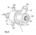
- the coolant pump 1 shown in FIG. 7 has, in addition to the drive of the pump impeller 32 in addition to the coolant electric motor 26, a drive wheel 106 arranged outside the pump housing 14.
- the drive gear 106 is aligned coaxially with the pump shaft 30 and mechanically couplable to the pump shaft 30 via a freewheel 108.
- the pump shaft 30 has an additional one Bearing 110 in the right-hand end of the housing part 18 in this illustration.
- the impeller 32 can be driven in addition to the electric motor 26 from the outside, for example via a belt or a pinion.
- the coolant pump 1 can be driven primarily mechanically via the example formed as a pulley drive wheel 106.
- the drive wheel 106 is decoupled via the freewheel 110 from the pump shaft 30 for this purpose.
- the drive wheel 106 At standstill and at low speeds of the internal combustion engine, for example, takes a low-cost electric motor pump drive at a constant speed. At higher speeds of the internal combustion engine, the drive wheel 106 overtakes the electric motor.
- This pump variant can also be used in electrical systems with low electrical power. It represents a cost-effective alternative to expensive brushless drive motors. A pumping capacity is ensured even in the event of a failure of the electric motor.
- FIG. 8 The variant of the coolant pump 1 shown in longitudinal section in FIG. 7 is illustrated in FIG. 8 in a three-dimensional view for a better understanding of the spatial allocation of the components.
- FIGS. 9 to 11 show a further variant of a coolant pump 1.
- the further variant of a coolant pump 1 shown in FIG. 9 in longitudinal section and in FIG. 10 in an enlarged detail and in FIG. 11 in three-dimensional view corresponds structurally essentially to the coolant pump 1 discussed in FIGS. 1 to 6 or equivalent components are provided for simplicity with the same reference numerals.
- FIGS. 9 to 11 of a drive of the directional control valve 40 via an expansion element 112 makes use of the volume change of the expansion element 112 as a function of the temperature prevailing in the pressure connection 34 of the coolant mixture flowing therethrough.
- expansion element 112 comes in the variant shown here, for example, wax used.
- the wax used here has a melting point at about 85 ° C.
- the wax is present as wax element 112 solidified in the cold state.
- the wax element 112 is spatially close to the pump outlet or the discharge port 34 or adjacent. It learns by the demarcation against the passing coolant flowing metallic inner shell 114 any temperature change in the coolant flowing to the engine ZM directly. Temperature influences from the outside are prevented by the insulating effect of the pump housing 14 made of plastic.
- the resulting change in volume is transmitted via a membrane 116 to a stored in a reservoir 118 transmission medium or coolant 120.
- the coolant 120 may be, for example, a water / glycol mixture.
- the spiral spring 73 shown in the embodiments of FIGS. 1 to 8, which provided there to ensure a fail-safe position of the directional valve 40 is now used to achieve a closing function in the directional control valve variant shown here, and no longer used to create a fail-safe position.
- the valve spool 72 is in the relaxed state of the spring 127 in a position "bypass open” or "cooler inlet closed” before. Accordingly, heating the expansion element 112 made in wax and the resulting volume expansion of the wax leads to a curvature of the membrane 116 and thus to a change in the volume of the reservoir 118, which ultimately results in a displacement of coolant 120 from the reservoir 118 into the cylinder chamber 126.
- the drive of the directional control valve 40 via an expansion element 112 offers the additional advantage over an electromagnetic drive that considerable weight can be saved.
- a drive of the directional control valve 40 via an electromagnet 76 as illustrated in Figures 1 to 8, means additional weight by the electromagnet 76.
- the light expansion element 112 in conjunction with the designed for a hydraulic drive valve slide 72 its weight and partially also play some cost advantages.
- expansion element 112 not shown here cooling and / or heating elements. This can, possibly using the existing control device or CPU 100, corresponding temperature sensors and possibly control circuits or the like, active on the volume expansion of the expansion element 112 to adjust, if necessary, other control states of the directional valve 40, than those that would arise by itself.
- the coolant 120 can be introduced into the storage chamber 118 or into the system by means of a filling opening 130 which can be closed by a screw plug 128.
- the running in wax expansion element 112 is so dimensionally stable in a cold state that it can be installed as a finished component when assembling the pump 1 with the same.
- Sealing rings 132 or the like serve to seal the valve spool 72 against the housing 14.
- FIG. 10 shows particularly clearly how the spring 127 forms a force pair with the expansion element 112 via the transmission medium 120 and generates a permanent counterforce to the expansion element 112.
- the expansion element 112 commercial wax wax can be used.
- the transfer medium or coolant 120 may be a water / glycol mixture.
- the filled with coolant 120 storage space 118, connecting lines 122 and 124 and cylinder chamber 126 formed hydraulic system 134 is filled bubble-free with overpressure during assembly of the coolant pump.
- the expansion element 112 formed of wax is inserted during assembly of the pump 1 in the housing 14, in the space 136 of the metallic cylinder jacket 114, which limits the radial clearance of the impeller 32 and the inner wall of the elastomeric membrane 116, that is hermetically delimited.
- the wax has a melting point of about 85 ° C. Influence of the wax 112 is possible in principle via a heating and / or a cooling element.
- FIG. 11 The variant of the coolant pump 1 shown in longitudinal section in FIG. 9 and in an enlarged partial section in FIG. 10 is illustrated in FIG. 11 in a three-dimensional view for a better understanding of the spatial allocation of the components.
- the structural design of the wax element is matched to the structural conditions of the coolant pump.
- the with the expansion element ultimately hydraulically driven directional control valve acts advantageously similar to an electrically adjustable thermostat.
- a map-controlled thermostat is a component that has a positive influence on the fuel consumption and the reduction of the emission.
- Conventional thermostats are set to a fixed opening temperature that can not be changed.
- an electrically controllable map thermostat the opening temperature of a valve can be varied depending on various parameters, e.g. Load, rotational speed, ignition angle, outside temperature, engine oil temperature, driving speed, etc.
- the wax element may optionally be additionally heated or cooled.
- a non-illustrated rod heater can be used. This takes over the heating of the wax element while it is in direct contact with the wax.
- the heating of the rod heater can be done for example via a coiled on a ceramic body resistance wire.
- Unheated so that the thus formed thermostat can be set for example to a temperature of 110 ° C. By heating the temperature can be lowered, for example, to about 70 ° C. The full opening temperature is thus reached at 15 ° C above the normal opening temperature.
- the reaction time of the thermostat can be influenced by heating power, immersion depth of the rod heater in the wax element, and the surface design of the wax element.
- an electronics unit was developed by the applicant. This makes it possible to process all input variables used in engine management.
- the required outputs for example via appropriate control circuits, the control device or CPU 100 or the like, are subsequently activated.
- the links are freely programmable depending on the internal combustion engine.
- the program can then be stored, for example, in the engine electronics of the respective internal combustion engine. A separate electronics is not required.
- the present invention provides for the first time a coolant pump for a coolant circuit of an automotive internal combustion engine having at least one radiator circuit and a bypass circuit.
- the coolant pump housing has a suction nozzle, a bypass nozzle and a discharge nozzle, and arranged in the coolant pump housing coolant pump electric motor, the motor housing is flowed around by the coolant, and drives a pump impeller via a pump shaft, as well as an integrated in the coolant pump housing directional control valve.
- the suction nozzle is for the first time arranged in the region of the pump impeller facing away from the end of the pump motor.
- the bypass nozzle is further arranged in a region downstream of the suction nozzle.
- the discharge nozzle is arranged in a region downstream of the bypass nozzle.
Landscapes
- Engineering & Computer Science (AREA)
- Mechanical Engineering (AREA)
- General Engineering & Computer Science (AREA)
- Chemical & Material Sciences (AREA)
- Combustion & Propulsion (AREA)
- Physics & Mathematics (AREA)
- Thermal Sciences (AREA)
- Structures Of Non-Positive Displacement Pumps (AREA)
- Lift Valve (AREA)
- Magnetically Actuated Valves (AREA)
- Multiple-Way Valves (AREA)
- Lubrication Of Internal Combustion Engines (AREA)
- Compression-Type Refrigeration Machines With Reversible Cycles (AREA)
Claims (22)
- Pompe de fluide réfrigérant (1) pour un circuit de fluide réfrigérant (2) d'un moteur à combustion interne de véhicule (10) comportant au moins un circuit de radiateur (4) et un circuit de dérivation (8), avec :- un carter de pompe de fluide réfrigérant (14) qui comporte une tubulure d'aspiration (22) pour l'amenée (ZK) à partir du radiateur (6), une tubulure de dérivation (24) pour l'amenée (ZB) à partir du circuit de dérivation (8) et une tubulure de refoulement (34) pour l'alimentation (ZM) du fluide réfrigérant au moteur du véhicule automobile (10),- un moteur électrique de pompe de fluide réfrigérant (26) placé dans le carter de pompe de fluide réfrigérant (14) dont le carter de moteur (28) est parcouru par le fluide réfrigérant et qui entraîne un rotor de pompe (32) par l'intermédiaire d'un arbre de pompe (30), et- un distributeur (40) intégré dans le carter de pompe de fluide réfrigérant (14),caractérisée en ce que- la tubulure d'aspiration (22) est disposée dans la zone (42) d'extrémité (44) du moteur de pompe (26) opposée au rotor de pompe (32),- la tubulure de dérivation (24) est disposée dans une zone (42) située en aval de la tubulure d'aspiration (22),- la tubulure de refoulement (34) est disposée dans une zone (42) située en aval de la tubulure de dérivation (24), et- seul le fluide réfrigérant (KZK) qui peut être aspiré à travers la tubulure d'aspiration (22) sous forme d'amenée (ZK) à partir du radiateur (6) peut passer devant le moteur de pompe (26) dans un flux de chemise (50), à travers un canal d'écoulement (56) délimité, en particulier, par la paroi extérieure (52) du carter de moteur de pompe (28) et la paroi intérieure (54) du carter de pompe (14) dirigée vers elle et/ou la paroi intérieure (60) du distributeur (40) dirigée vers elle.
- Pompe de fluide réfrigérant (1) selon la revendication 1, caractérisée en ce que le fluide réfrigérant (KZK) du circuit de dérivation (8) qui peut être aspiré à travers la tubulure de dérivation (24) peut être mélangé au fluide réfrigérant (KZK) venant du circuit de radiateur (4) par le distributeur (40), un orifice (62) de la tubulure de dérivation (24), qui peut être ouvert et refermé avec le distributeur (40), étant disposé dans une zone (42) en amont du rotor de pompe (32).
- Pompe de fluide réfrigérant (1) selon la revendication 2, caractérisée en ce que l'orifice (62) du distributeur (40) se trouve dans une zone (42) entre le rotor de pompe (32) et l'extrémité (64) du canal d'écoulement (56) se trouvant en aval.
- Pompe de fluide réfrigérant (1) selon l'une quelconque des revendications 1 à 3, caractérisée en ce que le moteur de pompe (26) et l'arbre de pompe (30) sont disposés coaxialement à l'axe longitudinal X du carter de pompe (14).
- Pompe de fluide réfrigérant (1) selon l'une quelconque des revendications 1 à 4, caractérisée en ce que le canal d'écoulement (56) délimité par la paroi extérieure (52) du carter de moteur (28) entourant le moteur de pompe (26) et la paroi intérieure (54) du carter de pompe (14) dirigée vers elle et/ou la paroi intérieure (60) du distributeur (40) dirigée vers elle présente une section transversale annulaire à travers laquelle le fluide réfrigérant (KZK), qui peut être aspiré à travers la tubulure d'aspiration (22) pour l'amenée (ZK) à partir du radiateur (6), peut passer devant le moteur de pompe (26) dans un flux de chemise (56) entourant le carter de moteur (28) en forme d'anneau.
- Pompe de fluide réfrigérant (1) selon l'une quelconque des revendications 1 à 5, caractérisée en ce que le canal d'écoulement (56) présente une section transversale (66) constante dans le sens d'écoulement, un rétrécissement du plus grand diamètre à l'extrémité du canal d'écoulement (56), jusqu'au diamètre intérieur (70) de la tubulure de refoulement (34), étant réalisé entre l'extrémité (68) du moteur de pompe (26) se trouvant en aval et le rotor de pompe (32).
- Pompe de fluide réfrigérant (1) selon l'une quelconque des revendications 1 à 6, caractérisée en ce que le distributeur (40) peut être commuté en continu entre une position fermée "dérivation fermée" et une position ouverte "dérivation ouverte".
- Pompe de fluide réfrigérant (1) selon l'une quelconque des revendications 1 à 7, caractérisée en ce que le distributeur (40) est un tiroir de soupape (72) déplaçable dans la direction longitudinale X de la pompe de fluide réfrigérant (1).
- Pompe de fluide réfrigérant (1) selon la revendication 8, caractérisée en ce que le tiroir de soupape est réalisé sous forme d'une douille cylindrique (72).
- Pompe de fluide réfrigérant (1) selon l'une quelconque des revendications 8 ou 9, caractérisée en ce que le tiroir de soupape (72) est déplaçable au moyen d'un actionneur, comme par exemple un électroaimant de commande (76), un élément en matériau dilatable (112), un élément de pression hydrostatique ou un autre élément du même genre.
- Pompe de fluide réfrigérant (1) selon l'une quelconque des revendications 8 à 10, caractérisée en ce que le tiroir de soupape (72) comporte, an aval dans la zone de l'orifice (62), une garniture d'étanchéité (86) annulaire rotative placée radialement à l'intérieur qui, à l'état fermé "dérivation fermée" du distributeur (40), obture de manière étanche l'orifice (62) de ce dernier contre un siège de garniture d'étanchéité annulaire (90) du carter de pompe (14) à l'aide d'une surface de contact (88) et/ou qui, à l'état ouvert "dérivation ouverte" du distributeur (40), obture de manière étanche le canal d'écoulement (56) contre le carter de moteur de pompe (28) ou le carter d'arbre de pompe (94) à l'aide d'une lèvre d'étanchéité (92) dirigée radialement vers l'intérieur.
- Pompe de fluide réfrigérant (1) selon la revendication 11, caractérisée en ce que la surface de la garniture d'étanchéité (86) dirigée radialement vers l'intérieur présente un profil correspondant au profil opposé du carter de moteur (28) ou du carter d'arbre de pompe (94).
- Pompe de fluide réfrigérant (1) selon l'une quelconque des revendications 8 à 12, caractérisée en ce que l'électroaimant de commande (76) du distributeur (72) comporte un induit (74) qui est formé par la douille cylindrique du tiroir de soupape (72).
- Pompe de fluide réfrigérant (1) selon la revendication 13, caractérisée en ce que l'électroaimant de commande (76) entoure un support de bobine (78) disposé dans le carter de pompe (14) qui entoure l'induit (74).
- Pompe de fluide réfrigérant (1) selon l'une quelconque des revendications 1 à 14, caractérisée en ce qu'un retour (38), par exemple pour un circuit de chauffage, un échangeur de chaleur d'huile d'engrenages, un échangeur de chaleur d'huile de lubrification, un circuit de refroidissement de bloc-cylindres ou un autre élément du même genre, débouche dans le carter de pompe (14), en aval après la tubulure de dérivation (24) et avant le rotor de pompe (32).
- Pompe de fluide réfrigérant (1) selon l'une quelconque des revendications 1 à 15, caractérisée en ce que le carter de pompe (14) est constitué de deux parties (16, 18).
- Pompe de fluide réfrigérant (1) selon l'une quelconque des revendications 1 à 16, caractérisée en ce que l'électroaimant de commande (76) comporte des contacts de bobine (96) orientés dans la direction longitudinale X qui, lors de l'assemblage des deux parties de carter (16, 18), peuvent être mis en contact avec un dispositif de réglage (100) installé dans l'autre partie du carter (18), comme par exemple une CPU ou un autre dispositif du même genre, au moyen de contacts corrélés (98).
- Pompe de fluide réfrigérant (1) selon l'une quelconque des revendications 1 à 17, caractérisée en ce que, en plus de l'entraînement du rotor de pompe (32) par le moteur électrique de pompe de fluide réfrigérant (26), il est prévu une roue d'entraînement (106) disposée coaxialement à l'arbre de pompe (30) à l'extérieur du carter de pompe (14) qui est couplée à l'arbre de pompe (30) par une roue libre (108).
- Pompe de fluide réfrigérant (1) selon l'une quelconque des revendications 1 à 18, caractérisée en ce que l'élément en matériau dilatable (112) est en relation active avec le distributeur (40) au moyen de conduits de raccordement (122, 124) de telle manière que le distributeur (40) peut être commuté hydrauliquement par une variation de volume de l'élément en matériau dilatable (112).
- Pompe de fluide réfrigérant (1) selon l'une quelconque des revendications 1 à 19, caractérisée en ce que l'élément en matériau dilatable (112) est constitué de cire dont la variation de volume en fonction de la température peut être transmise au distributeur (72) commandé hydrauliquement au moyen d'un fluide réfrigérant séparé (120) et de conduits de raccordement (122, 124).
- Pompe de fluide réfrigérant (1) selon l'une quelconque des revendications 1 à 20, caractérisée en ce que l'élément en matériau dilatable (112) constitué de cire est disposé dans une zone dans le carter de pompe (14) adjacente à la tubulure de refoulement (34) et séparé du fluide réfrigérant (120) associé, séparé, à l'aide d'une membrane (116) de telle manière qu'une variation de volume de l'élément en matériau dilatable (112) en fonction de la température peut être transmise au fluide réfrigérant (120) qui est lui-même déplaçable dans un compartiment de cylindre (126) du distributeur (72) ainsi commandé hydrauliquement au moyen de conduits de raccordement (122, 124).
- Procédé pour le transport de fluide réfrigérant avec une pompe de fluide réfrigérant (1) pour un circuit de fluide réfrigérant (2) d'un moteur à combustion interne de véhicule (10) comportant au moins un circuit de radiateur (4) et un circuit de dérivation (8), avec les étapes suivantes :- alimentation du fluide réfrigérant entre le radiateur (6) et la pompe de fluide réfrigérant (1) à travers une tubulure d'aspiration (22) du carter de pompe de fluide réfrigérant (14) pour l'amenée (ZK),- alimentation du fluide réfrigérant entre le circuit de dérivation (8) et la pompe de fluide réfrigérant (1) à travers une tubulure de dérivation (24) du carter de pompe de fluide réfrigérant (14) pour l'amenée (ZB),- retour du fluide réfrigérant entre la pompe de fluide réfrigérant (1) et le moteur à combustion interne de véhicule (10) à travers une tubulure de refoulement (34) pour le recyclage du fluide réfrigérant (ZM),- recirculation du fluide réfrigérant (1) avec un rotor (32) disposée dans le carter de pompe de fluide réfrigérant (14) qui est entraînée par un moteur électrique de pompe de fluide réfrigérant (26) au moyen d'un arbre de pompe (30), le moteur (26) étant parcouru par le fluide réfrigérant,- réglage du rapport de mélange des flux de fluide réfrigérant circulant à travers la pompe de fluide réfrigérant avec un distributeur (40) intégré dans le carter de pompe de fluide réfrigérant (14),caractérisé en ce que- le fluide réfrigérant provenant du radiateur (6) est alimenté dans la zone (42) de l'extrémité (44) du moteur de pompe (26) opposée à la roue à aubes de pompe (32) au moyen de la tubulure d'aspiration (22),- le fluide réfrigérant provenant de la dérivation est alimenté dans une zone (42) située en aval de la tubulure d'aspiration (22) au moyen de la tubulure de dérivation (24),- le fluide réfrigérant est évacué au moyen de la tubulure de refoulement (34) dans une zone (42) située en aval de la tubulure de dérivation (24), et- seul le fluide réfrigérant (KZK) transporté à travers la tubulure d'aspiration (22) sous forme d'amenée (ZK) à partir du radiateur (6) passe devant le moteur de pompe (26) dans un flux de chemise (50), à travers un canal d'écoulement (56) délimité, en particulier, par la paroi extérieure (52) du carter de moteur de pompe (28) et la paroi intérieure (54) du carter de pompe (14) dirigée vers elle et/ou la paroi intérieure (60) du distributeur (40) dirigée vers elle.
Applications Claiming Priority (3)
| Application Number | Priority Date | Filing Date | Title |
|---|---|---|---|
| DE10314526 | 2003-03-31 | ||
| DE2003114526 DE10314526B4 (de) | 2003-03-31 | 2003-03-31 | Kühlmittelpumpe, insbesondere strömungsgekühlte elekrische Kühlmittelpumpe mit integriertem Wegeventil |
| PCT/EP2004/002455 WO2004088143A1 (fr) | 2003-03-31 | 2004-03-10 | Pompe de fluide refrigerant, en particulier, pompe electrique a refroidissement hydraulique, a distributeur integre, et procede correspondant |
Publications (3)
| Publication Number | Publication Date |
|---|---|
| EP1608876A1 EP1608876A1 (fr) | 2005-12-28 |
| EP1608876B1 true EP1608876B1 (fr) | 2007-07-18 |
| EP1608876B8 EP1608876B8 (fr) | 2007-10-03 |
Family
ID=33016092
Family Applications (1)
| Application Number | Title | Priority Date | Filing Date |
|---|---|---|---|
| EP04718939A Expired - Lifetime EP1608876B8 (fr) | 2003-03-31 | 2004-03-10 | Pompe de fluide refrigerant, en particulier, pompe electrique a refroidissement hydraulique, a distributeur integre, et procede correspondant |
Country Status (7)
| Country | Link |
|---|---|
| US (1) | US7334543B2 (fr) |
| EP (1) | EP1608876B8 (fr) |
| JP (1) | JP4545143B2 (fr) |
| AT (1) | ATE367532T1 (fr) |
| DE (2) | DE10314526B4 (fr) |
| ES (1) | ES2286621T3 (fr) |
| WO (1) | WO2004088143A1 (fr) |
Cited By (1)
| Publication number | Priority date | Publication date | Assignee | Title |
|---|---|---|---|---|
| CN102439317A (zh) * | 2009-04-30 | 2012-05-02 | 欧根·施密特博士仪器和泵制造有限责任公司 | 可切换的冷却剂泵 |
Families Citing this family (51)
| Publication number | Priority date | Publication date | Assignee | Title |
|---|---|---|---|---|
| DE102004054637B4 (de) * | 2004-11-12 | 2007-04-26 | Geräte- und Pumpenbau GmbH Dr. Eugen Schmidt | Regelbare Kühlmittelpumpe |
| DE102005024827A1 (de) * | 2005-05-27 | 2006-11-30 | Fev Motorentechnik Gmbh | Mechatronische Kühlmittelpumpen-Antriebsverbindung |
| EP1767788B1 (fr) * | 2005-09-23 | 2008-08-06 | Coprecitec, S.L. | Pompe pour électroménager |
| DE102005056200A1 (de) * | 2005-11-25 | 2007-06-06 | Audi Ag | Pumpe für ein flüssiges Medium, insbesondere Kühlmittelpumpe, sowie Stellelement für eine solche Pumpe |
| DE102005062200B3 (de) * | 2005-12-23 | 2007-02-22 | Geräte- und Pumpenbau GmbH Dr. Eugen Schmidt | Regelbare Kühlmittelpumpe |
| DE102006034952B4 (de) * | 2006-07-28 | 2008-04-03 | Audi Ag | Regelbare Axialpumpe für einen Kühlkreislauf einer Verbrennungskraftmaschine |
| WO2008057522A1 (fr) * | 2006-11-06 | 2008-05-15 | Borgwarner Inc. | Pompe à air régénérative à double entrée |
| DE202006018152U1 (de) * | 2006-11-28 | 2008-04-10 | Weidmüller Interface GmbH & Co. KG | Zusatzanschluss für Reihenklemmen |
| DE102007004187B4 (de) | 2007-01-27 | 2008-09-25 | Geräte- und Pumpenbau GmbH Dr. Eugen Schmidt | Regelbare Kühlmittelpumpe |
| JP2010001739A (ja) * | 2008-02-20 | 2010-01-07 | Toyota Motor Corp | サーモスタット装置 |
| US8029248B2 (en) * | 2008-06-05 | 2011-10-04 | Dana Canada Corporation | Integrated coolant pumping module |
| DE102008030768A1 (de) * | 2008-06-28 | 2009-12-31 | Audi Ag | Anordnung eines Drehschiebers mit einer Wasserpumpe |
| WO2010081161A1 (fr) * | 2009-01-12 | 2010-07-15 | Tourgee & Associates, Inc. | Procédé et appareil pour monter des instruments optiquement couplés dans des environnements rigoureux |
| ATE511607T1 (de) * | 2009-02-26 | 2011-06-15 | Grundfos Management As | Pumpenaggregat |
| DE102009012923B3 (de) * | 2009-03-12 | 2010-07-01 | Geräte- und Pumpenbau GmbH Dr. Eugen Schmidt | Regelbare Kühlmittelpumpe |
| DE102009014038B4 (de) * | 2009-03-19 | 2015-07-02 | Schaeffler Technologies AG & Co. KG | Wärmemanagement-Modul mit prismatischem Regelschieber |
| BRPI0905651B1 (pt) * | 2009-11-03 | 2020-03-10 | Embraco Indústria De Compressores E Soluções Em Refrigeração Ltda | Arranjo de montagem de eixo excêntrico em bloco de compressor de refrigeração |
| US8731789B2 (en) * | 2010-09-28 | 2014-05-20 | Ford Global Technologies, Llc | Transmission fluid heating via heat exchange with engine cylinder walls |
| CN103119264B (zh) * | 2010-11-12 | 2015-06-03 | 爱信精机株式会社 | 控制阀 |
| DE102010053510B4 (de) | 2010-12-04 | 2014-01-23 | Geräte- und Pumpenbau GmbH Dr. Eugen Schmidt | Kühlmittelpumpe |
| CN102121477B (zh) * | 2011-03-31 | 2012-12-26 | 宁波巨神制泵实业有限公司 | 大型潜水排污泵 |
| WO2014098656A1 (fr) * | 2012-12-21 | 2014-06-26 | Volvo Truck Corporation | Système de refroidissement destiné à un véhicule hybride à alimentation mécanique et hydraulique |
| DE102013210288B3 (de) | 2013-04-30 | 2014-07-10 | Magna Powertrain Ag & Co. Kg | Gleichstromantrieb für ein Kühlsystem eines Kraftfahrzeuges |
| CN105745450B (zh) * | 2013-11-16 | 2017-10-24 | 博泽沃尔兹堡汽车零部件有限公司 | 电动冷却剂泵 |
| DE102013019298A1 (de) | 2013-11-16 | 2015-05-21 | Brose Fahrzeugteile GmbH & Co. Kommanditgesellschaft, Würzburg | Stelleinrichtung einer elektrischen Kühlmittelpumpe |
| DE102013019299B4 (de) | 2013-11-16 | 2017-10-12 | Brose Fahrzeugteile GmbH & Co. Kommanditgesellschaft, Würzburg | Elektromotorische Kühlmittelpumpe mit im Pumpengehäuse angeordnetem und vom Kühlmittel betätigten Stellaktor |
| DE102014101437A1 (de) * | 2014-02-05 | 2015-08-06 | Eto Magnetic Gmbh | Elektromagnetventil sowie Verbrennungsmotorkühlsystem mit Elektromagnetventil |
| CN104005963B (zh) * | 2014-05-23 | 2016-03-02 | 哈尔滨电气动力装备有限公司 | 小型核电站用主泵结构 |
| DE102014113412B3 (de) * | 2014-09-17 | 2015-09-24 | Nidec Gpm Gmbh | Strömungsgekühlte Kühlmittelpumpe mit Nassläufer |
| DE102015000805B3 (de) * | 2015-01-22 | 2016-01-21 | Nidec Gpm Gmbh | Regelbare Kühlmittelpumpe |
| JP2017014984A (ja) * | 2015-06-30 | 2017-01-19 | 株式会社荏原製作所 | 流体機械 |
| CN108368950B (zh) * | 2015-10-02 | 2019-08-23 | 康卓(马克多夫)有限公司 | 用于冷却发动机的冷却回路布置和方法 |
| US10655528B2 (en) * | 2015-11-04 | 2020-05-19 | Volvo Truck Corporation | Method of operating an internal combustion engine |
| US10295076B2 (en) * | 2016-11-02 | 2019-05-21 | Schaeffler Technologies AG & Co. KG | Modular electro-mechanical rotary valve with activated seal interface |
| WO2018102636A1 (fr) | 2016-12-02 | 2018-06-07 | Carrier Corporation | Système de chauffage de transport de cargaison |
| CN106640594A (zh) * | 2016-12-14 | 2017-05-10 | 江门市腾飞科技有限公司 | 一种增压泵及具有该增压泵的纯水机 |
| DE102017102769B3 (de) | 2017-02-13 | 2018-06-07 | Nidec Gpm Gmbh | Hybridantrieb für eine Kühlmittelpumpe |
| DE102017118264A1 (de) | 2017-08-10 | 2019-02-14 | Nidec Gpm Gmbh | Kühlmittelpumpe mit Hybridantrieb und Steuerungsverfahren |
| DE102017120191B3 (de) | 2017-09-01 | 2018-12-06 | Nidec Gpm Gmbh | Regelbare Kühlmittelpumpe für Haupt- und Nebenförderkreislauf |
| KR20190072934A (ko) * | 2017-12-18 | 2019-06-26 | 현대자동차주식회사 | 차량용 워터 펌프 |
| KR102451915B1 (ko) * | 2018-03-27 | 2022-10-06 | 현대자동차 주식회사 | 차량용 냉각수 펌프 및 이를 포함한 냉각 시스템 |
| KR101936853B1 (ko) | 2018-05-16 | 2019-01-09 | 지엠비코리아(주) | 멀티웨이밸브 장치 |
| KR20200116676A (ko) * | 2019-04-02 | 2020-10-13 | 현대자동차주식회사 | 차량용 워터펌프 |
| DE102019120235B3 (de) * | 2019-07-26 | 2020-09-17 | Bayerische Motoren Werke Aktiengesellschaft | Elektromechanische Wasserpumpe mit einem Gehäuse |
| DE102019122717A1 (de) * | 2019-08-23 | 2021-02-25 | Nidec Gpm Gmbh | Regelbare Kühlmittelpumpe mit Kolbenstangenführung |
| DE102020003431A1 (de) | 2020-06-08 | 2021-12-09 | Daimler Ag | Kühlmittelpumpe für ein Kraftfahrzeug, insbesondere für einen Kraftwagen |
| US11863051B2 (en) | 2021-05-13 | 2024-01-02 | General Electric Company | Thermal management system |
| CN114483281A (zh) * | 2022-01-29 | 2022-05-13 | 重庆长安汽车股份有限公司 | 一种发动机的水泵布置结构、发动机及汽车 |
| DE102022202217B4 (de) * | 2022-03-04 | 2025-12-31 | Schaeffler Technologies AG & Co. KG | Ventil-Pumpen-Einheit mit je nach Drehrichtung eines Elektromotors betreibbarer Funktion |
| DE102022202215B4 (de) * | 2022-03-04 | 2025-12-31 | Schaeffler Technologies AG & Co. KG | Ventil-Pumpen-Einheit mit einem einen Elektromotor umschließenden Mehrwegeventil |
| DE102023212572A1 (de) * | 2023-12-13 | 2025-06-18 | Stellantis Auto Sas | Ventil mit integrierter pumpe |
Family Cites Families (14)
| Publication number | Priority date | Publication date | Assignee | Title |
|---|---|---|---|---|
| DE3739494A1 (de) * | 1987-11-21 | 1989-06-01 | Sueddeutsche Kuehler Behr | Ventil zur steuerung des kuehlwasserumlaufs bei brennkraftmaschinen |
| DE3817952A1 (de) * | 1988-05-27 | 1989-11-30 | Wahler Gmbh & Co Gustav | Kuehlwasserregler fuer brennkraftmaschinen |
| DE9013459U1 (de) * | 1990-09-25 | 1992-01-30 | Robert Bosch Gmbh, 7000 Stuttgart | Kühlsystem für Brennkraftmaschinen |
| US5415134A (en) * | 1993-10-29 | 1995-05-16 | Stewart Components | Engine cooling system for cooling a vehicle engine |
| DE4422749C2 (de) * | 1994-06-29 | 1996-08-29 | Holter Gmbh & Co | Pumpenschutzventil |
| DE19534108A1 (de) * | 1995-09-14 | 1997-03-20 | Wilo Gmbh | Kühler eines Kraftfahrzeugmotors |
| DE19809123B4 (de) * | 1998-03-04 | 2005-12-01 | Daimlerchrysler Ag | Wasserpumpe für den Kühlkreislauf einer Brennkraftmaschine |
| AT412664B (de) * | 1998-04-27 | 2005-05-25 | Andritz Ag Maschf | Lagerung für eine pumpe, insbesondere hauptkühlmittelpumpe |
| DE19846737A1 (de) * | 1998-10-12 | 2000-04-20 | Voit Stefan | Elektrisch betreibbares Pumpelement zum Einsatz in einem Kühlsystem sowie Wärmetauscher eines Kühlsystems |
| DE19943981A1 (de) * | 1999-09-14 | 2001-03-15 | Behr Thermot Tronik Gmbh & Co | Ventil zum Regeln der Temperatur eines Verbrennungsmotors |
| DE10047387B4 (de) * | 2000-09-25 | 2013-09-12 | GPM Geräte- und Pumpenbau GmbH Dr. Eugen Schmidt, Merbelsrod | Elektrisch angetriebene Kühlmittelpumpe |
| JP2002130190A (ja) * | 2000-10-19 | 2002-05-09 | Koyo Seiko Co Ltd | 電動ウォータポンプ装置 |
| US6499442B2 (en) * | 2000-12-18 | 2002-12-31 | Thomas J. Hollis | Integral water pump/electronic engine temperature control valve |
| DE10207653C1 (de) * | 2002-02-22 | 2003-09-25 | Gpm Geraete Und Pumpenbau Gmbh | Elektrische Kühlmittelpumpe mit integriertem Ventil, sowie Verfahren zu dessen Steuerung |
-
2003
- 2003-03-31 DE DE2003114526 patent/DE10314526B4/de not_active Expired - Fee Related
-
2004
- 2004-03-10 US US10/551,467 patent/US7334543B2/en not_active Expired - Lifetime
- 2004-03-10 EP EP04718939A patent/EP1608876B8/fr not_active Expired - Lifetime
- 2004-03-10 WO PCT/EP2004/002455 patent/WO2004088143A1/fr not_active Ceased
- 2004-03-10 DE DE200450004367 patent/DE502004004367D1/de not_active Expired - Lifetime
- 2004-03-10 ES ES04718939T patent/ES2286621T3/es not_active Expired - Lifetime
- 2004-03-10 AT AT04718939T patent/ATE367532T1/de not_active IP Right Cessation
- 2004-03-10 JP JP2006504621A patent/JP4545143B2/ja not_active Expired - Fee Related
Cited By (2)
| Publication number | Priority date | Publication date | Assignee | Title |
|---|---|---|---|---|
| CN102439317A (zh) * | 2009-04-30 | 2012-05-02 | 欧根·施密特博士仪器和泵制造有限责任公司 | 可切换的冷却剂泵 |
| CN102439317B (zh) * | 2009-04-30 | 2014-07-02 | 欧根·施密特博士仪器和泵制造有限责任公司 | 可切换的冷却剂泵 |
Also Published As
| Publication number | Publication date |
|---|---|
| JP4545143B2 (ja) | 2010-09-15 |
| WO2004088143A1 (fr) | 2004-10-14 |
| DE502004004367D1 (de) | 2007-08-30 |
| DE10314526A1 (de) | 2004-10-21 |
| ATE367532T1 (de) | 2007-08-15 |
| EP1608876B8 (fr) | 2007-10-03 |
| ES2286621T3 (es) | 2007-12-01 |
| US7334543B2 (en) | 2008-02-26 |
| EP1608876A1 (fr) | 2005-12-28 |
| JP2006522259A (ja) | 2006-09-28 |
| US20060216166A1 (en) | 2006-09-28 |
| DE10314526B4 (de) | 2007-11-29 |
Similar Documents
| Publication | Publication Date | Title |
|---|---|---|
| EP1608876B1 (fr) | Pompe de fluide refrigerant, en particulier, pompe electrique a refroidissement hydraulique, a distributeur integre, et procede correspondant | |
| DE10302629B4 (de) | Stromregelventil | |
| DE19606202B4 (de) | Kühlsystem für einen Verbrennungsmotor | |
| DE102005040897B4 (de) | Wärmeaustauscheraufbau eines Automatikgetriebes | |
| DE4420841A1 (de) | Heizvorrichtung für Kraftfahrzeuge | |
| DE69835959T2 (de) | Vorrichtung zur montage des abgasrückführventils | |
| DE10239288B4 (de) | Drehmomentwandler, der mit einer Wandlersperrkupplung versehen ist und für eine effektive Wärmeabführung angeordnet ist | |
| DE10025500A1 (de) | Brennkraftmaschine mit Kühlkreislauf und einem an diesen angeschlossenen Heizungswärmetauscher | |
| DE112009001025T5 (de) | Elektronisch gesteuerter Viskolüfterantrieb mit Buchse | |
| DE3211793A1 (de) | Kuehlmitteltemperatur-regelungsanlage fuer einen kraftfahrzeug-verbrennungsmotor | |
| DE102010050605A1 (de) | Vorrichtung zur Regelung eines Kühlmittelstroms sowie Kühlsystem | |
| DE102016214122A1 (de) | Wärmeleitsystem für ein Fahrzeug und Verfahren zu dessen Verwendung und Herstellung | |
| DE102019118585A1 (de) | Vorrichtung und verfahren zum steuern einer motorkühlmitteldurchflussrate mittels eines thermostats | |
| DE102008015707B4 (de) | Wasserpumpe und Verfahren zu ihrer Steuerung | |
| DE102018217006B4 (de) | Kühlkreislauf für Fahrzeuge mit einem Durchflusssteuerventil | |
| DE102009014050A1 (de) | Wärmemanagementmodul mit axial hydraulisch betriebenem Ventilglied | |
| DE102013222825A1 (de) | Einzellagerung einer Drehschieberwelle mit reduziertem Radialspiel und angepasster Führungslänge | |
| DE19908146B4 (de) | Vorrichtung zum Verändern der Steuerzeiten von Gaswechselventilen einer Brennkraftmaschine | |
| DE4446152C2 (de) | Heizsystem, insbesondere für Kraftfahrzeuge | |
| EP1511643B1 (fr) | Dispositif de chauffage pour des vehicules automobiles | |
| EP3290713A1 (fr) | Pompe de refroidissement pour le secteur automobile ainsi qu'un circuit de refroidissement pour un moteur à combustion interne | |
| DE102022214071A1 (de) | Antriebsstrang für ein Kraftfahrzeug | |
| EP0658708B1 (fr) | Système pour le contrôle de la température du fluide hydraulique d'une boíte de vitesses automatique et convertisseur de couple | |
| DE10318711A1 (de) | Vorrichtung zum Antrieb der Kühlmittelpumpe einer Brennkraftmaschine | |
| DE3728330C2 (fr) |
Legal Events
| Date | Code | Title | Description |
|---|---|---|---|
| PUAI | Public reference made under article 153(3) epc to a published international application that has entered the european phase |
Free format text: ORIGINAL CODE: 0009012 |
|
| 17P | Request for examination filed |
Effective date: 20050923 |
|
| AK | Designated contracting states |
Kind code of ref document: A1 Designated state(s): AT BE BG CH CY CZ DE DK EE ES FI FR GB GR HU IE IT LI LU MC NL PL PT RO SE SI SK TR |
|
| AX | Request for extension of the european patent |
Extension state: AL LT LV MK |
|
| DAX | Request for extension of the european patent (deleted) | ||
| GRAP | Despatch of communication of intention to grant a patent |
Free format text: ORIGINAL CODE: EPIDOSNIGR1 |
|
| GRAS | Grant fee paid |
Free format text: ORIGINAL CODE: EPIDOSNIGR3 |
|
| GRAA | (expected) grant |
Free format text: ORIGINAL CODE: 0009210 |
|
| AK | Designated contracting states |
Kind code of ref document: B1 Designated state(s): AT BE BG CH CY CZ DE DK EE ES FI FR GB GR HU IE IT LI LU MC NL PL PT RO SE SI SK TR |
|
| REG | Reference to a national code |
Ref country code: GB Ref legal event code: FG4D Free format text: NOT ENGLISH |
|
| REG | Reference to a national code |
Ref country code: SE Ref legal event code: TRGR |
|
| GBT | Gb: translation of ep patent filed (gb section 77(6)(a)/1977) |
Effective date: 20070718 |
|
| REG | Reference to a national code |
Ref country code: CH Ref legal event code: EP |
|
| REF | Corresponds to: |
Ref document number: 502004004367 Country of ref document: DE Date of ref document: 20070830 Kind code of ref document: P |
|
| REG | Reference to a national code |
Ref country code: IE Ref legal event code: FG4D Free format text: LANGUAGE OF EP DOCUMENT: GERMAN |
|
| REG | Reference to a national code |
Ref country code: ES Ref legal event code: FG2A Ref document number: 2286621 Country of ref document: ES Kind code of ref document: T3 |
|
| ET | Fr: translation filed | ||
| PG25 | Lapsed in a contracting state [announced via postgrant information from national office to epo] |
Ref country code: PT Free format text: LAPSE BECAUSE OF FAILURE TO SUBMIT A TRANSLATION OF THE DESCRIPTION OR TO PAY THE FEE WITHIN THE PRESCRIBED TIME-LIMIT Effective date: 20071218 Ref country code: BG Free format text: LAPSE BECAUSE OF FAILURE TO SUBMIT A TRANSLATION OF THE DESCRIPTION OR TO PAY THE FEE WITHIN THE PRESCRIBED TIME-LIMIT Effective date: 20071018 Ref country code: FI Free format text: LAPSE BECAUSE OF FAILURE TO SUBMIT A TRANSLATION OF THE DESCRIPTION OR TO PAY THE FEE WITHIN THE PRESCRIBED TIME-LIMIT Effective date: 20070718 Ref country code: NL Free format text: LAPSE BECAUSE OF FAILURE TO SUBMIT A TRANSLATION OF THE DESCRIPTION OR TO PAY THE FEE WITHIN THE PRESCRIBED TIME-LIMIT Effective date: 20070718 |
|
| NLV1 | Nl: lapsed or annulled due to failure to fulfill the requirements of art. 29p and 29m of the patents act | ||
| PG25 | Lapsed in a contracting state [announced via postgrant information from national office to epo] |
Ref country code: PL Free format text: LAPSE BECAUSE OF FAILURE TO SUBMIT A TRANSLATION OF THE DESCRIPTION OR TO PAY THE FEE WITHIN THE PRESCRIBED TIME-LIMIT Effective date: 20070718 |
|
| REG | Reference to a national code |
Ref country code: IE Ref legal event code: FD4D |
|
| PLBI | Opposition filed |
Free format text: ORIGINAL CODE: 0009260 |
|
| PG25 | Lapsed in a contracting state [announced via postgrant information from national office to epo] |
Ref country code: DK Free format text: LAPSE BECAUSE OF FAILURE TO SUBMIT A TRANSLATION OF THE DESCRIPTION OR TO PAY THE FEE WITHIN THE PRESCRIBED TIME-LIMIT Effective date: 20070718 Ref country code: GR Free format text: LAPSE BECAUSE OF FAILURE TO SUBMIT A TRANSLATION OF THE DESCRIPTION OR TO PAY THE FEE WITHIN THE PRESCRIBED TIME-LIMIT Effective date: 20071019 |
|
| 26 | Opposition filed |
Opponent name: PIERBURG PUMP TECHNOLOGIES GMBH Effective date: 20080408 |
|
| PLAX | Notice of opposition and request to file observation + time limit sent |
Free format text: ORIGINAL CODE: EPIDOSNOBS2 |
|
| PG25 | Lapsed in a contracting state [announced via postgrant information from national office to epo] |
Ref country code: SK Free format text: LAPSE BECAUSE OF FAILURE TO SUBMIT A TRANSLATION OF THE DESCRIPTION OR TO PAY THE FEE WITHIN THE PRESCRIBED TIME-LIMIT Effective date: 20070718 Ref country code: IE Free format text: LAPSE BECAUSE OF FAILURE TO SUBMIT A TRANSLATION OF THE DESCRIPTION OR TO PAY THE FEE WITHIN THE PRESCRIBED TIME-LIMIT Effective date: 20070718 Ref country code: CZ Free format text: LAPSE BECAUSE OF FAILURE TO SUBMIT A TRANSLATION OF THE DESCRIPTION OR TO PAY THE FEE WITHIN THE PRESCRIBED TIME-LIMIT Effective date: 20070718 |
|
| PLBB | Reply of patent proprietor to notice(s) of opposition received |
Free format text: ORIGINAL CODE: EPIDOSNOBS3 |
|
| PG25 | Lapsed in a contracting state [announced via postgrant information from national office to epo] |
Ref country code: RO Free format text: LAPSE BECAUSE OF FAILURE TO SUBMIT A TRANSLATION OF THE DESCRIPTION OR TO PAY THE FEE WITHIN THE PRESCRIBED TIME-LIMIT Effective date: 20070718 |
|
| BERE | Be: lapsed |
Owner name: GERATE- UND PUMPENBAU G.M.B.H. Effective date: 20080331 |
|
| PG25 | Lapsed in a contracting state [announced via postgrant information from national office to epo] |
Ref country code: MC Free format text: LAPSE BECAUSE OF NON-PAYMENT OF DUE FEES Effective date: 20080331 |
|
| REG | Reference to a national code |
Ref country code: CH Ref legal event code: PL |
|
| PG25 | Lapsed in a contracting state [announced via postgrant information from national office to epo] |
Ref country code: CH Free format text: LAPSE BECAUSE OF NON-PAYMENT OF DUE FEES Effective date: 20080331 Ref country code: EE Free format text: LAPSE BECAUSE OF FAILURE TO SUBMIT A TRANSLATION OF THE DESCRIPTION OR TO PAY THE FEE WITHIN THE PRESCRIBED TIME-LIMIT Effective date: 20070718 Ref country code: LI Free format text: LAPSE BECAUSE OF NON-PAYMENT OF DUE FEES Effective date: 20080331 |
|
| PG25 | Lapsed in a contracting state [announced via postgrant information from national office to epo] |
Ref country code: BE Free format text: LAPSE BECAUSE OF NON-PAYMENT OF DUE FEES Effective date: 20080331 |
|
| PG25 | Lapsed in a contracting state [announced via postgrant information from national office to epo] |
Ref country code: SI Free format text: LAPSE BECAUSE OF FAILURE TO SUBMIT A TRANSLATION OF THE DESCRIPTION OR TO PAY THE FEE WITHIN THE PRESCRIBED TIME-LIMIT Effective date: 20070718 |
|
| PG25 | Lapsed in a contracting state [announced via postgrant information from national office to epo] |
Ref country code: CY Free format text: LAPSE BECAUSE OF FAILURE TO SUBMIT A TRANSLATION OF THE DESCRIPTION OR TO PAY THE FEE WITHIN THE PRESCRIBED TIME-LIMIT Effective date: 20070718 |
|
| PG25 | Lapsed in a contracting state [announced via postgrant information from national office to epo] |
Ref country code: AT Free format text: LAPSE BECAUSE OF NON-PAYMENT OF DUE FEES Effective date: 20080310 |
|
| PLBP | Opposition withdrawn |
Free format text: ORIGINAL CODE: 0009264 |
|
| PLBD | Termination of opposition procedure: decision despatched |
Free format text: ORIGINAL CODE: EPIDOSNOPC1 |
|
| PLBM | Termination of opposition procedure: date of legal effect published |
Free format text: ORIGINAL CODE: 0009276 |
|
| STAA | Information on the status of an ep patent application or granted ep patent |
Free format text: STATUS: OPPOSITION PROCEDURE CLOSED |
|
| 27C | Opposition proceedings terminated |
Effective date: 20091224 |
|
| PG25 | Lapsed in a contracting state [announced via postgrant information from national office to epo] |
Ref country code: HU Free format text: LAPSE BECAUSE OF FAILURE TO SUBMIT A TRANSLATION OF THE DESCRIPTION OR TO PAY THE FEE WITHIN THE PRESCRIBED TIME-LIMIT Effective date: 20080119 Ref country code: LU Free format text: LAPSE BECAUSE OF NON-PAYMENT OF DUE FEES Effective date: 20080310 |
|
| PG25 | Lapsed in a contracting state [announced via postgrant information from national office to epo] |
Ref country code: TR Free format text: LAPSE BECAUSE OF FAILURE TO SUBMIT A TRANSLATION OF THE DESCRIPTION OR TO PAY THE FEE WITHIN THE PRESCRIBED TIME-LIMIT Effective date: 20070718 |
|
| REG | Reference to a national code |
Ref country code: FR Ref legal event code: PLFP Year of fee payment: 12 |
|
| PGFP | Annual fee paid to national office [announced via postgrant information from national office to epo] |
Ref country code: SE Payment date: 20150323 Year of fee payment: 12 |
|
| REG | Reference to a national code |
Ref country code: DE Ref legal event code: R082 Ref document number: 502004004367 Country of ref document: DE Representative=s name: KUHNEN & WACKER PATENT- UND RECHTSANWALTSBUERO, DE Ref country code: DE Ref legal event code: R081 Ref document number: 502004004367 Country of ref document: DE Owner name: NIDEC GPM GMBH, DE Free format text: FORMER OWNER: GERAETE- UND PUMPENBAU GMBH, 98673 MERBELSROD, DE |
|
| REG | Reference to a national code |
Ref country code: FR Ref legal event code: RM Effective date: 20151228 Ref country code: FR Ref legal event code: CD Owner name: NIDEC GPM GMBH, DE Effective date: 20151228 |
|
| REG | Reference to a national code |
Ref country code: FR Ref legal event code: PLFP Year of fee payment: 13 |
|
| REG | Reference to a national code |
Ref country code: ES Ref legal event code: PC2A Owner name: NIDEC GPM GMBH Effective date: 20160404 |
|
| PGFP | Annual fee paid to national office [announced via postgrant information from national office to epo] |
Ref country code: DE Payment date: 20160307 Year of fee payment: 13 Ref country code: ES Payment date: 20160215 Year of fee payment: 13 Ref country code: IT Payment date: 20160302 Year of fee payment: 13 |
|
| PGFP | Annual fee paid to national office [announced via postgrant information from national office to epo] |
Ref country code: GB Payment date: 20160309 Year of fee payment: 13 |
|
| PGFP | Annual fee paid to national office [announced via postgrant information from national office to epo] |
Ref country code: FR Payment date: 20160331 Year of fee payment: 13 |
|
| REG | Reference to a national code |
Ref country code: SE Ref legal event code: EUG |
|
| PG25 | Lapsed in a contracting state [announced via postgrant information from national office to epo] |
Ref country code: SE Free format text: LAPSE BECAUSE OF NON-PAYMENT OF DUE FEES Effective date: 20160311 |
|
| REG | Reference to a national code |
Ref country code: DE Ref legal event code: R119 Ref document number: 502004004367 Country of ref document: DE |
|
| GBPC | Gb: european patent ceased through non-payment of renewal fee |
Effective date: 20170310 |
|
| REG | Reference to a national code |
Ref country code: FR Ref legal event code: ST Effective date: 20171130 |
|
| PG25 | Lapsed in a contracting state [announced via postgrant information from national office to epo] |
Ref country code: DE Free format text: LAPSE BECAUSE OF NON-PAYMENT OF DUE FEES Effective date: 20171003 Ref country code: FR Free format text: LAPSE BECAUSE OF NON-PAYMENT OF DUE FEES Effective date: 20170331 |
|
| PG25 | Lapsed in a contracting state [announced via postgrant information from national office to epo] |
Ref country code: IT Free format text: LAPSE BECAUSE OF NON-PAYMENT OF DUE FEES Effective date: 20170310 Ref country code: GB Free format text: LAPSE BECAUSE OF NON-PAYMENT OF DUE FEES Effective date: 20170310 |
|
| REG | Reference to a national code |
Ref country code: ES Ref legal event code: FD2A Effective date: 20180702 |
|
| PG25 | Lapsed in a contracting state [announced via postgrant information from national office to epo] |
Ref country code: ES Free format text: LAPSE BECAUSE OF NON-PAYMENT OF DUE FEES Effective date: 20170311 |