EP1608955B1 - Appareil de surveillance en temps reel de reaction biochimique - Google Patents
Appareil de surveillance en temps reel de reaction biochimique Download PDFInfo
- Publication number
- EP1608955B1 EP1608955B1 EP04725637.5A EP04725637A EP1608955B1 EP 1608955 B1 EP1608955 B1 EP 1608955B1 EP 04725637 A EP04725637 A EP 04725637A EP 1608955 B1 EP1608955 B1 EP 1608955B1
- Authority
- EP
- European Patent Office
- Prior art keywords
- light
- real
- reaction
- time monitoring
- lamp
- Prior art date
- Legal status (The legal status is an assumption and is not a legal conclusion. Google has not performed a legal analysis and makes no representation as to the accuracy of the status listed.)
- Expired - Lifetime
Links
- 238000012544 monitoring process Methods 0.000 title claims description 30
- 238000005842 biochemical reaction Methods 0.000 title claims description 14
- 238000006243 chemical reaction Methods 0.000 claims description 72
- 230000003287 optical effect Effects 0.000 claims description 24
- 230000005540 biological transmission Effects 0.000 claims description 13
- 239000000523 sample Substances 0.000 description 28
- 230000005855 radiation Effects 0.000 description 12
- 230000035945 sensitivity Effects 0.000 description 8
- 238000010586 diagram Methods 0.000 description 7
- 238000005516 engineering process Methods 0.000 description 6
- 238000001514 detection method Methods 0.000 description 5
- 238000003753 real-time PCR Methods 0.000 description 5
- 238000004458 analytical method Methods 0.000 description 4
- 239000012472 biological sample Substances 0.000 description 3
- 238000010835 comparative analysis Methods 0.000 description 3
- 238000001816 cooling Methods 0.000 description 3
- 238000010438 heat treatment Methods 0.000 description 3
- 238000003384 imaging method Methods 0.000 description 3
- 230000001678 irradiating effect Effects 0.000 description 3
- 238000002032 lab-on-a-chip Methods 0.000 description 3
- 238000000034 method Methods 0.000 description 3
- 239000013307 optical fiber Substances 0.000 description 3
- 238000000926 separation method Methods 0.000 description 3
- 230000003321 amplification Effects 0.000 description 2
- 239000012620 biological material Substances 0.000 description 2
- 238000005251 capillar electrophoresis Methods 0.000 description 2
- 238000003199 nucleic acid amplification method Methods 0.000 description 2
- NVNLLIYOARQCIX-MSHCCFNRSA-N Nisin Chemical compound N1C(=O)[C@@H](CC(C)C)NC(=O)C(=C)NC(=O)[C@@H]([C@H](C)CC)NC(=O)[C@@H](NC(=O)C(=C/C)/NC(=O)[C@H](N)[C@H](C)CC)CSC[C@@H]1C(=O)N[C@@H]1C(=O)N2CCC[C@@H]2C(=O)NCC(=O)N[C@@H](C(=O)N[C@H](CCCCN)C(=O)N[C@@H]2C(NCC(=O)N[C@H](C)C(=O)N[C@H](CC(C)C)C(=O)N[C@H](CCSC)C(=O)NCC(=O)N[C@H](CS[C@@H]2C)C(=O)N[C@H](CC(N)=O)C(=O)N[C@H](CCSC)C(=O)N[C@H](CCCCN)C(=O)N[C@@H]2C(N[C@H](C)C(=O)N[C@@H]3C(=O)N[C@@H](C(N[C@H](CC=4NC=NC=4)C(=O)N[C@H](CS[C@@H]3C)C(=O)N[C@H](CO)C(=O)N[C@H]([C@H](C)CC)C(=O)N[C@H](CC=3NC=NC=3)C(=O)N[C@H](C(C)C)C(=O)NC(=C)C(=O)N[C@H](CCCCN)C(O)=O)=O)CS[C@@H]2C)=O)=O)CS[C@@H]1C NVNLLIYOARQCIX-MSHCCFNRSA-N 0.000 description 1
- 108010053775 Nisin Proteins 0.000 description 1
- 230000015556 catabolic process Effects 0.000 description 1
- 238000006731 degradation reaction Methods 0.000 description 1
- 238000011161 development Methods 0.000 description 1
- 239000000835 fiber Substances 0.000 description 1
- 230000002068 genetic effect Effects 0.000 description 1
- 239000011521 glass Substances 0.000 description 1
- 150000004820 halides Chemical class 0.000 description 1
- 229910052736 halogen Inorganic materials 0.000 description 1
- 150000002367 halogens Chemical class 0.000 description 1
- 238000005286 illumination Methods 0.000 description 1
- 238000001459 lithography Methods 0.000 description 1
- 239000000463 material Substances 0.000 description 1
- 239000004309 nisin Substances 0.000 description 1
- 235000010297 nisin Nutrition 0.000 description 1
- 150000007523 nucleic acids Chemical class 0.000 description 1
- 102000039446 nucleic acids Human genes 0.000 description 1
- 108020004707 nucleic acids Proteins 0.000 description 1
- 239000004033 plastic Substances 0.000 description 1
- 230000000644 propagated effect Effects 0.000 description 1
- 230000001902 propagating effect Effects 0.000 description 1
- 238000012827 research and development Methods 0.000 description 1
- 239000004065 semiconductor Substances 0.000 description 1
- 229910052710 silicon Inorganic materials 0.000 description 1
- 239000010703 silicon Substances 0.000 description 1
- 238000001228 spectrum Methods 0.000 description 1
- 238000005728 strengthening Methods 0.000 description 1
- 239000000126 substance Substances 0.000 description 1
- 230000001360 synchronised effect Effects 0.000 description 1
Images


Classifications
-
- C—CHEMISTRY; METALLURGY
- C12—BIOCHEMISTRY; BEER; SPIRITS; WINE; VINEGAR; MICROBIOLOGY; ENZYMOLOGY; MUTATION OR GENETIC ENGINEERING
- C12M—APPARATUS FOR ENZYMOLOGY OR MICROBIOLOGY; APPARATUS FOR CULTURING MICROORGANISMS FOR PRODUCING BIOMASS, FOR GROWING CELLS OR FOR OBTAINING FERMENTATION OR METABOLIC PRODUCTS, i.e. BIOREACTORS OR FERMENTERS
- C12M41/00—Means for regulation, monitoring, measurement or control, e.g. flow regulation
- C12M41/06—Means for regulation, monitoring, measurement or control, e.g. flow regulation of illumination
-
- G—PHYSICS
- G01—MEASURING; TESTING
- G01N—INVESTIGATING OR ANALYSING MATERIALS BY DETERMINING THEIR CHEMICAL OR PHYSICAL PROPERTIES
- G01N21/00—Investigating or analysing materials by the use of optical means, i.e. using sub-millimetre waves, infrared, visible or ultraviolet light
- G01N21/01—Arrangements or apparatus for facilitating the optical investigation
- G01N21/03—Cuvette constructions
- G01N21/0332—Cuvette constructions with temperature control
-
- C—CHEMISTRY; METALLURGY
- C12—BIOCHEMISTRY; BEER; SPIRITS; WINE; VINEGAR; MICROBIOLOGY; ENZYMOLOGY; MUTATION OR GENETIC ENGINEERING
- C12M—APPARATUS FOR ENZYMOLOGY OR MICROBIOLOGY; APPARATUS FOR CULTURING MICROORGANISMS FOR PRODUCING BIOMASS, FOR GROWING CELLS OR FOR OBTAINING FERMENTATION OR METABOLIC PRODUCTS, i.e. BIOREACTORS OR FERMENTERS
- C12M31/00—Means for providing, directing, scattering or concentrating light
- C12M31/02—Means for providing, directing, scattering or concentrating light located outside the reactor
- C12M31/04—Mirrors
-
- C—CHEMISTRY; METALLURGY
- C12—BIOCHEMISTRY; BEER; SPIRITS; WINE; VINEGAR; MICROBIOLOGY; ENZYMOLOGY; MUTATION OR GENETIC ENGINEERING
- C12M—APPARATUS FOR ENZYMOLOGY OR MICROBIOLOGY; APPARATUS FOR CULTURING MICROORGANISMS FOR PRODUCING BIOMASS, FOR GROWING CELLS OR FOR OBTAINING FERMENTATION OR METABOLIC PRODUCTS, i.e. BIOREACTORS OR FERMENTERS
- C12M31/00—Means for providing, directing, scattering or concentrating light
- C12M31/02—Means for providing, directing, scattering or concentrating light located outside the reactor
- C12M31/06—Lenses
-
- C—CHEMISTRY; METALLURGY
- C12—BIOCHEMISTRY; BEER; SPIRITS; WINE; VINEGAR; MICROBIOLOGY; ENZYMOLOGY; MUTATION OR GENETIC ENGINEERING
- C12M—APPARATUS FOR ENZYMOLOGY OR MICROBIOLOGY; APPARATUS FOR CULTURING MICROORGANISMS FOR PRODUCING BIOMASS, FOR GROWING CELLS OR FOR OBTAINING FERMENTATION OR METABOLIC PRODUCTS, i.e. BIOREACTORS OR FERMENTERS
- C12M41/00—Means for regulation, monitoring, measurement or control, e.g. flow regulation
- C12M41/12—Means for regulation, monitoring, measurement or control, e.g. flow regulation of temperature
-
- G—PHYSICS
- G01—MEASURING; TESTING
- G01N—INVESTIGATING OR ANALYSING MATERIALS BY DETERMINING THEIR CHEMICAL OR PHYSICAL PROPERTIES
- G01N21/00—Investigating or analysing materials by the use of optical means, i.e. using sub-millimetre waves, infrared, visible or ultraviolet light
- G01N21/62—Systems in which the material investigated is excited whereby it emits light or causes a change in wavelength of the incident light
- G01N21/63—Systems in which the material investigated is excited whereby it emits light or causes a change in wavelength of the incident light optically excited
- G01N21/64—Fluorescence; Phosphorescence
- G01N21/645—Specially adapted constructive features of fluorimeters
- G01N21/6452—Individual samples arranged in a regular 2D-array, e.g. multiwell plates
-
- B—PERFORMING OPERATIONS; TRANSPORTING
- B01—PHYSICAL OR CHEMICAL PROCESSES OR APPARATUS IN GENERAL
- B01L—CHEMICAL OR PHYSICAL LABORATORY APPARATUS FOR GENERAL USE
- B01L7/00—Heating or cooling apparatus; Heat insulating devices
- B01L7/52—Heating or cooling apparatus; Heat insulating devices with provision for submitting samples to a predetermined sequence of different temperatures, e.g. for treating nucleic acid samples
-
- G—PHYSICS
- G01—MEASURING; TESTING
- G01N—INVESTIGATING OR ANALYSING MATERIALS BY DETERMINING THEIR CHEMICAL OR PHYSICAL PROPERTIES
- G01N21/00—Investigating or analysing materials by the use of optical means, i.e. using sub-millimetre waves, infrared, visible or ultraviolet light
- G01N21/62—Systems in which the material investigated is excited whereby it emits light or causes a change in wavelength of the incident light
- G01N21/63—Systems in which the material investigated is excited whereby it emits light or causes a change in wavelength of the incident light optically excited
- G01N21/64—Fluorescence; Phosphorescence
- G01N21/645—Specially adapted constructive features of fluorimeters
- G01N2021/6484—Optical fibres
Definitions
- the present invention relates to an apparatus for real-time monitoring chemical reaction between various biomaterials. More particularly, the present invention is directed to a real-time monitoring apparatus for biochemical reaction, which comprises a temperature control block system comprising a thermoelectric element, capable of supplying heat into a reaction tube, a heat transmission block which transmit the heat to the reaction tubes; a light irradiation source part comprising a lamp which irradiates light with uniform intensity to sample contained in the reaction tube, and optical waveguide; and optical system comprising a light receiving part for receiving fluorescence irradiated from the sample by the light emitted from the light irradiation source.
- a temperature control block system comprising a thermoelectric element, capable of supplying heat into a reaction tube, a heat transmission block which transmit the heat to the reaction tubes
- a light irradiation source part comprising a lamp which irradiates light with uniform intensity to sample contained in the reaction tube, and optical waveguide
- optical system comprising a light receiving part for receiving fluor
- the present invention relates to an apparatus for real-time monitoring chemical reaction between various biomaterials. More particularly, the present invention is directed to a real-time monitoring apparatus for biochemical reaction, which comprises a temperature control block system comprising a thermoelectric element, capable of supplying heat into a reaction tube, a heat transmission block which transmit the heat to the reaction tube; a light irradiation source part comprising a lamp which irradiates light with uniform intensity on sample contained in the reaction tube, and optical waveguide; and optical system comprising a light receiving part for receiving fluorescence irradiated from the sample by the light emitted from the light irradiation source.
- a temperature control block system comprising a thermoelectric element, capable of supplying heat into a reaction tube, a heat transmission block which transmit the heat to the reaction tube
- a light irradiation source part comprising a lamp which irradiates light with uniform intensity on sample contained in the reaction tube, and optical waveguide
- optical system comprising a light receiving part for receiving fluor
- lab-on-a-chip composed from glass, silicon or plastic material and manufactured through the lithography technology which has been employed for semiconductor chip, mounts micro-sized device for analyzing samples rapidly and sensitively.
- the above all procedures required for the analysis of sample i.e., pretreatment, reaction, separation, detection and etc., can be performed continuously.
- the time needed for the sample analysis can be reduced to second or minute level and also the amount of sample can be reduced to microliter level and the size of apparatus on which the chip is mounted can also be miniaturized.
- the lab-on-a-chip technology is based on the capillary electrophoresis developed by Harrison in early 1990s, and had been started to be known to the public by the fact that a small size lab. Device for the capillary electrophoresis analysis can be integrated into a single chip.
- the conventional real-time PCR apparatus is composed of the thermoelectric element, the heat transmitting block which transmit heat into reaction tubes which contains sample, the light irradiation source which irradiate light into sample contained in the reaction tube, and the light receiving part which accept the fluorescence generated from the sample.
- the progress of PCR can be checked in real-time by measuring the intensity of fluorescence generated from sample upon completion of each cycle by the operation of the thermoelectric element for cooling and heating repeatedly to carry out the reaction of biochemical sample contained in the tube.
- a halogen lamp and a metallic halide lamp have been employed as a light irradiation source.
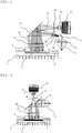
- a selective transmission filter (9) transmit selectively the light with preferred wavelength from the light radiated from the lamp (5) and then, the light thus selected irradiated into the sample contained in the tubes via a reflection mirror (18) and through a condensing lens (17).
- the sample contained in the tubes generate fluorescence by irradiation of light thus selected.
- the fluorescence thus generated is reflected by reflection mirror (18) and focused through condensing lens (17).
- the fluorescence thus focused from each tubes is imaged on a light receiving element of the light receiving part to indicate and record the progress of reaction, continuously.
- the light intensity generated from the light radiation lamp of the conventional apparatus is differentiated depends on the positions, i.e., the center or the edges of the facet of light beam. Consequently, the light intensity generally varied with gaussian curve along with central axis of the facet of light beam and maintain this distribution even through the condensing lens.
- the primary object of the present invention is to provide an apparatus for real-time monitoring the progress of biochemical reaction, which have technical part to irradiate light with uniform intensity over the whole area of the tube plate which is enlarged than that of prior art.
- the reaction tube plate of prior art is in general rectangular shape.
- the conventional light radiation system composed of a lamp and a lens, emits plane wave beam of which facet has round shape.
- some edge part of light beam should be eliminated to be fitted with the rectangular shaped tube plate. This problem lowers the efficiency of the source due to eliminated pat of light beam.
- US 4,213,703 discloses a sample holder and shutter assembly for photometers in which a stationary sample chamber body is mounted in close proximity to a photosensitive device. A light path is provided from the sample chamber to the photosensitive device and shutter means is provided for selectively interrupting and opening the light path between the photosensitive device and the sample chamber without moving the sample chamber.
- Heat exchange means including a heat pump and a heat reservoir are provided for maintaining a desired temperature in the sample chamber.
- US 6,272,269 discloses a fiber optic illumination system which includes a light source, a waveguide, and an optical fiber.
- the waveguide includes a straight collecting segment, a tapered condensing segment, and a straight homogenizing segment and conveys light from the light source to the optical fiber by transmission and/or internal reflection.
- Light transmitted by the optical fiber may be delivered to any one or more of a variety of light output devices, including diffusive flat panels, diffusive rods or wands, fluorescent light emitting converters, projectors, spectrum generators.
- EP 0 987 540 discloses an imaging device for biochemical or medical samples, the pulse mode light source of which incorporates flash lamps and a rotating mirror in an inclined position, the said mirror reflecting the light emitted by each flash lamp in turn along the same optical path to the sample.
- the flash lamps are switched on alternately in phases and synchronised with the rotating mirror and the emission light chopper, which comprises two rotating discs.
- the turning mirror directs the light at the sample from above and/or below.
- another object of the present invention is to provide a real time monitoring apparatus for biochemical reaction which can irradiate light with uniform intensity over the whole area of the reaction tube plate, even over the whole area of the reaction tube plate enlarged than that of prior art, by irradiating light beam through a light irradiation part via a mirror.
- the object of the present invention it to provide a real-time monitoring apparatus for biochemical reaction according to the appended claims.
- Another object of the present invention is to provide a real-time monitoring apparatus for biochemical reaction which has a ellipsoidal mirror associated with the lamp of the apparatus to get an uniform light intensity distribution.
- the light from the light radiation lamp (5) is focused into the light waveguide (8).
- the light in the light waveguide is propagated in a manner of total internal reflection.
- the light beam at the end of the light waveguide (8) become a uniform 2-dimensional light source and are focused on the samples contained in the reaction tubes (4) through the first condensing lens (10).
- the uniform light beam (31) there reaction progress may be more easily measured over the whole range of the reaction tubes.
- an apparatus capable of checking the progress of reaction more efficiently may be provided due to the reduced variation of radiation light intensity in each reaction tube by irradiating the light with uniform intensity over broader reaction tube area.
- the apparatus enables to process uniform reaction information while reacting various samples simultaneously in the reaction tubes.
- An object of the present invention is to provide a real-time monitoring apparatus for biochemical reaction with improved reaction monitoring sensitivity.
- the usage efficiency of light source is improved by increasing the amount of light irradiated into the reaction tubes, as the result of minimizing the loss of the light source in prior art by irradiating rectangular light beam adjusted to the aspect ratio of the rectangular reaction tube plate using a light waveguide (8).
- the present invention relates to a measuring and monitoring apparatus for reaction progress in real-time while reacting various samples.
- the temperature control block of the present invention is comprised of thermoelectric element (2) for repeating cooling and heating cycles and heat transmission block (3) for transmitting heat to reaction tubes containing samples. Moreover, a radiating plate (1) may be additionally provided for increasing the efficiency of the thermoelectric element.
- the optical system comprised of a light irradiation source and a light receiving part for measuring the amplified reaction progress in real-time is placed on a temperature control block.
- the light irradiation source of the present invention comprises a lamp (5) which irradiates light to a sample contained in reaction tubes, a Infra-Red cutting filter (6) intercepting the light from the lamp, an optical waveguide (8) and a first focusing lens (10) for obtaining uniform light beam of the light from the lamp in a wide area, a selective transmission filter 1 (9) for transmitting light of specific wavelength selectively to monitor a reaction progress in the tube, condensing lens 1 (17) for receiving the fluorescence (15) by the radiation light (16) and a second reflective mirror (11) which alters light path.
- the present invention employs an optical waveguide (8) placed in front of the light source to reduce of the difference in light intensity between the center and the edges of the tube plate and solves the problem of the prior art.
- the waveguide (8) is designed to irradiate the light beam from the light source uniformly over a wider range.
- the light beam from the light source experience a total internal reflection due to the refractive indexes between a propagating medium (n2) in the waveguide (8) and surrounding air (nl).
- the light beam entered into the waveguide (8) forms a uniform plane wave light source at the light outlet (27) thereof.
- light intensity is more densely distributed in the center and less densely distributed at the edges.
- the light intensity at the edges is merely about 50- 60% of that in the center. Due to the difference in light intensity, samples placed in the center shows a higher sensitivity and reaction level than the samples placed at the edges by the different amount of light intensity there between.
- the present invention solves the prior art problem by forming a lamp with parabolic or ellipsoidal mirror as the radiation light source.
- the optical waveguide (8) is designated to provide light intensity more uniformly over the broader cross-section of light beam.
- the waveguide (8) employs the difference in refractive indexes between the propagation medium (n2) and surrounding air (nl).
- Light beam where an incident angle (i) of the incident beam (29) has equal to or larger than a critical angle (c) experience total internal reflection (30) inside the waveguide (8).
- the incident beam (29) are emitted from the light outlet (27) through the waveguide (8) without loss in light intensity due to the light distribution. In this manner, a highly uniform 2-dimensional light source is formed at the light outlet (27) of the waveguide (8).
- the refractive index of the propagation medium in the optical waveguide (8) is preferably 1. 35-2. 0.
- the total internal reflection condition in a medium should satisfy that an incident angle (i) of incident light beam (29) is equal to or bigger than a critical angle (c).
- reference numeral 30 represents the reflected light beam, 26 for the emitting light beam, and 32 for the refracted light.
- sin (c) n2 (i (incident angle) > c (critical angle))
- a plane wave light source of the present invention with uniformly distributed intensity over the cross-section of light beam has more than 85% (21) of light intensity at the edges compared with the light intensity in the center of reaction tube plate (34) and enables to monitor the reaction progress more uniformly by achieving substantially improved light intensity uniformity compared with the prior art.
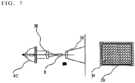
- the typical reaction tube plate (34) used for proceeding the reactions of the various biological samples simultaneously is usually a rectangular shape, while the prior art optical radiation system comprising a lamp and a lens generates plane wave light beam with a round-type cross-section.
- plane wave light beam with a round-type cross-section are adjusted to the shape of the rectangular reaction tube plate (34) and the remaining portions (35) unnecessary for the rectangular shape are removed.
- the removal of light beam (35) results to the removal of a portions of light beam from the light source lamp and causes graded efficiency of the light source.
- reference numeral 35 represents the removed light beam.
- the light waveguide (8) of the present invention has a shape of a rectangular cross-section (37) to be fitted with the aspect ratio of the rectangular plate (34) so that it is able to use the light from the lamp in it maximum efficiency because there are no light beam to be removed.
- the monitoring sensitivity of present invention is improved by increasing the light intensity irradiated on the plate to more than 20%.
- the reference numerals 21 and 24 represent the brightness distribution along the X-axis and Y-axis, respectively.
- Reference numerals 22 and 23 represent the brightness distribution along the X-axis and Y-axis, respectively, of prior art.
- the radiation light controlled to a plane wave light source shape is irradiated on the samples contained in the reaction tubes (4) placed on the plate through a first focusing lens (10), a first selective transmission filter (9), a second reflecting mirror (11) and a first condensing lens.
- the nucleic acid samples in the reaction tubes are amplified per every cycle by the temperature block and fluorescence is generated from the amplified samples by the radiation light.
- the light receiving part of the present invention comprises a second focusing mirror (13) imaging fluorescence (15) from the samples contained in the reaction tubes (4) to the direction of an imaging element by the first condensing lens (17) and the second reflecting mirror (11); a light receiving element (12) for recoding the imaged figure by the second focusing lens (13) and a second selective transmission filter (14) .
- the fluorescence (15) generated from the samples is imaged on the light receiving element (12) by a second focusing lens (13) through the condensing lens 1 (17), the reflecting mirror 2 (11) and the second selective transmission filter (14).
- the images by fluorescence of each sample are transferred to a computer which analyzes the changing reaction progress per every cycle. Furthermore, it is possible to compare and analyze while per each sample by reacting various biochemical samples in the reaction tube plate described analyzing the reaction progress for each sample.
- the real-time monitoring apparatus for biochemical reaction of the present invention employs the lamp (5) with the ellipsoidal-type mirror and the optical waveguide (8), and there may be capable of monitoring the biological reaction progress with uniform sensitivity over the whole reaction plate area over the whole reaction plate (34).
- the present invention efficiently performs the comparative analysis of various samples while reacting the various samples simultaneously on one reaction tube plate by monitoring the reaction progress of the samples contained in the reaction tubes between the center and the edges of the reaction tube plate, more accurately.
- the reaction progress of the samples contained in the reaction tubes is equal to in the center and at the edges while there are limitations when performing a comparative analysis of the reaction progress for the samples due to the difference in light intensity of measured fluorescence.
- the present invention overcomes the limitation of prior art. Therefore, the real-time monitoring apparatus for biochemical reaction of the present invention is able to provide an appropriate apparatus for performing a comparative analysis of the reaction progress of the various samples by minimizing variation of light detection sensitivity during the reaction in the reaction tube plate.
- the present invention provides a profile of the light beam from the light source which is adjusted to a rectangular shape to be fitted with the aspect ration of the rectangular shape of the reaction tube plate.
- This adjusted profile of the present invention excludes the necessity of removing some portions of the light beam in the prior art and enables to use the light beam from the light source lamp at the maximum efficiency which improves energy efficiency of the present apparatus accordingly.
Landscapes
- Health & Medical Sciences (AREA)
- Chemical & Material Sciences (AREA)
- Life Sciences & Earth Sciences (AREA)
- Bioinformatics & Cheminformatics (AREA)
- Biochemistry (AREA)
- General Health & Medical Sciences (AREA)
- Organic Chemistry (AREA)
- Zoology (AREA)
- Wood Science & Technology (AREA)
- Engineering & Computer Science (AREA)
- Analytical Chemistry (AREA)
- Physics & Mathematics (AREA)
- Biotechnology (AREA)
- Biomedical Technology (AREA)
- Microbiology (AREA)
- Sustainable Development (AREA)
- Pathology (AREA)
- Immunology (AREA)
- General Engineering & Computer Science (AREA)
- Genetics & Genomics (AREA)
- General Physics & Mathematics (AREA)
- Nuclear Medicine, Radiotherapy & Molecular Imaging (AREA)
- Thermal Sciences (AREA)
- Investigating, Analyzing Materials By Fluorescence Or Luminescence (AREA)
- Investigating Or Analysing Materials By Optical Means (AREA)
Claims (4)
- Appareil de surveillance en temps réel de réactions biochimiques, qui consiste en :- une plaque rectangulaire de tube de réaction (34) capable de contenir des tubes de réaction ;- un bloc de régulation de température comprenant un élément thermoélectrique (2) capable de fournir de la chaleur dans les tubes de réaction et un bloc de transmission de chaleur (3) qui transmet la chaleur aux tubes de réaction ;- une source d'irradiation lumineuse, qui irradie une lumière d'une intensité uniforme aux échantillons contenus dans les tubes de réaction, comprenant une lampe (5), et un guide d'onde optique (8), qui a une coupe transversale rectangulaire ajustée au rapport de forme de la plaque rectangulaire de tube de réaction ;- un système optique comprenant un premier miroir réfléchissant (7), une première lentille de condensation (10), un second miroir réfléchissant (11), et une seconde lentille de condensation (17), dans lequel le second miroir réfléchissant (11) modifie le trajet lumineux passant à travers au moins une extrémité du guide d'onde optique pour fournir une conception optique repliée, dans lequel l'ordre des éléments optiques dans le trajet optique est la lampe (5), le premier miroir réfléchissant (7), le guide d'onde optique (8), la première lentille de condensation (10), le second miroir réfléchissant (11), et la seconde lentille de condensation (17) ; et- une partie réceptrice (12, 13, 14) pour la réception, par le second miroir réfléchissant (11), d'une fluorescence irradiée depuis l'échantillon par la lumière émise depuis la source d'irradiation lumineuse.
- Appareil de surveillance en temps réel selon la revendication 1, dans lequel la lampe (5) inclut un miroir réfléchissant parabolique ou ellipsoïdal.
- Appareil de surveillance en temps réel selon la revendication 1, dans lequel l'indice de réfraction d'un milieu du guide d'onde optique est de 1,35 à 2,0.
- Appareil de surveillance en temps réel selon la revendication 2, comprenant en outre une lentille de focalisation (36) lorsque la lampe (5) est pourvue d'un miroir parabolique.
Applications Claiming Priority (3)
| Application Number | Priority Date | Filing Date | Title |
|---|---|---|---|
| KR2003021145 | 2003-04-03 | ||
| KR20030021145 | 2003-04-03 | ||
| PCT/KR2004/000785 WO2004088291A1 (fr) | 2003-04-03 | 2004-04-03 | Appareil de surveillance en temps reel de reaction biochimique |
Publications (3)
| Publication Number | Publication Date |
|---|---|
| EP1608955A1 EP1608955A1 (fr) | 2005-12-28 |
| EP1608955A4 EP1608955A4 (fr) | 2007-09-05 |
| EP1608955B1 true EP1608955B1 (fr) | 2020-04-29 |
Family
ID=36639331
Family Applications (1)
| Application Number | Title | Priority Date | Filing Date |
|---|---|---|---|
| EP04725637.5A Expired - Lifetime EP1608955B1 (fr) | 2003-04-03 | 2004-04-03 | Appareil de surveillance en temps reel de reaction biochimique |
Country Status (6)
| Country | Link |
|---|---|
| US (1) | US8139210B2 (fr) |
| EP (1) | EP1608955B1 (fr) |
| JP (1) | JP4751821B2 (fr) |
| KR (1) | KR100794703B1 (fr) |
| CN (1) | CN1798969B (fr) |
| WO (1) | WO2004088291A1 (fr) |
Families Citing this family (14)
| Publication number | Priority date | Publication date | Assignee | Title |
|---|---|---|---|---|
| KR100647317B1 (ko) * | 2005-02-03 | 2006-11-23 | 삼성전자주식회사 | 다채널 형광 측정용 광학계 및 이를 채용한 다채널 형광시료 분석 장치 |
| WO2008136591A1 (fr) | 2007-05-04 | 2008-11-13 | Sk Energy Co., Ltd. | Procédé pour produire des polycarbonates et complexe de coordination utilisé pour ce faire |
| KR101089045B1 (ko) | 2007-06-28 | 2011-12-02 | (주)바이오니아 | 핵산증폭반응 산물의 실시간 모니터링장치 |
| DE102008023299A1 (de) * | 2008-05-08 | 2009-11-19 | Micropelt Gmbh | Aufnahme für eine Probe |
| KR101423936B1 (ko) * | 2009-03-11 | 2014-07-29 | (주)바이오니아 | 실시간 핵산 분석 통합 장치 및 이를 이용한 타겟 핵산의 검출방법 |
| JP4698766B2 (ja) * | 2009-06-12 | 2011-06-08 | 三井造船株式会社 | 蛍光検出装置および蛍光検出方法 |
| JP5443494B2 (ja) * | 2009-08-21 | 2014-03-19 | 株式会社東芝 | 光学素子および表示装置 |
| CN107377025B (zh) * | 2011-09-30 | 2020-11-10 | 生命技术公司 | 用于生物分析的系统和方法 |
| KR101545848B1 (ko) | 2012-04-09 | 2015-08-21 | (주)바이오니아 | 핵산중합효소로 핵산을 검출하는데 사용되는 고민감도 핵산준비방법 |
| US9371555B2 (en) * | 2012-06-01 | 2016-06-21 | Concordia Laboratories Inc. | Lighting systems and methods of using lighting systems for in vitro potency assay for photofrin |
| KR102078085B1 (ko) | 2013-12-31 | 2020-02-17 | 주식회사 미코바이오메드 | 농식품의 식중독균 검출용 랩온어칩 기반의 초고속 실시간 pcr 장치, 및 이를 이용한 식중독 검출방법 |
| KR101840530B1 (ko) | 2016-01-08 | 2018-05-04 | 고려대학교 산학협력단 | 표면 측정 센싱 기반의 실시간 핵산 증폭 측정 장치 |
| WO2018191252A1 (fr) * | 2017-04-10 | 2018-10-18 | Cornell University | Système et procédé d'amplification isotherme d'acides nucléiques |
| KR102379488B1 (ko) * | 2020-07-30 | 2022-03-25 | 한림대학교 산학협력단 | 형광 집광이 가능한 중합효소 연쇄반응 형광 검출 장치 및 이의 형광 집광 장치, 방법 및 프로그램 |
Citations (3)
| Publication number | Priority date | Publication date | Assignee | Title |
|---|---|---|---|---|
| US4213703A (en) * | 1978-05-30 | 1980-07-22 | Beckman Instruments, Inc. | Photometer with stationary sample holder and rotatable shutter |
| EP0987540A2 (fr) * | 1998-09-17 | 2000-03-22 | Wallac Oy | Appareil pour la représentation d'échantillons |
| US6272269B1 (en) * | 1999-11-16 | 2001-08-07 | Dn Labs Inc. | Optical fiber/waveguide illumination system |
Family Cites Families (14)
| Publication number | Priority date | Publication date | Assignee | Title |
|---|---|---|---|---|
| DE2408646A1 (de) * | 1974-02-22 | 1975-08-28 | Max Planck Gesellschaft | Reaktionskinetisches messgeraet |
| US4689797A (en) * | 1985-08-19 | 1987-08-25 | Gte Laboratories Incorporated | High power single spatial mode semiconductor laser |
| JPH06250137A (ja) | 1993-02-23 | 1994-09-09 | Casio Comput Co Ltd | 外観検査方法及びその装置 |
| CA2200455A1 (fr) * | 1994-09-20 | 1996-03-28 | Louis R. Piloco | Dispositif de stabilisation et d'homogeneisation de l'eclairement |
| US5674000A (en) * | 1996-02-08 | 1997-10-07 | Bright Solutions, Inc. | Light source for use in leak detection in heating, ventilating, and air conditioning systems that utilize environmentally-safe materials |
| JPH09288237A (ja) * | 1996-02-20 | 1997-11-04 | Bunshi Bio Photonics Kenkyusho:Kk | 暗視野落射顕微鏡 |
| JP3697007B2 (ja) | 1997-02-10 | 2005-09-21 | 浜松ホトニクス株式会社 | マルチタイタープレート分析装置 |
| EP1087223A4 (fr) | 1998-06-12 | 2004-06-16 | Asahi Chemical Ind | Analyseur |
| JP3855485B2 (ja) | 1998-09-09 | 2006-12-13 | 東ソー株式会社 | スキャナー型蛍光検出装置 |
| JP4203685B2 (ja) | 1998-11-10 | 2009-01-07 | 株式会社ニコン | 検査装置 |
| JP3855517B2 (ja) * | 1999-01-27 | 2006-12-13 | 東ソー株式会社 | 多サンプル対応のスキャナー型蛍光検出装置 |
| JP3473557B2 (ja) * | 1999-07-26 | 2003-12-08 | セイコーエプソン株式会社 | 照明装置及びプロジェクタ |
| AU2884401A (en) * | 2000-01-28 | 2001-08-07 | Asahi Kasei Kabushiki Kaisha | Photothermic transducing spectroscopic analyzer |
| US7157047B2 (en) * | 2001-02-09 | 2007-01-02 | Pss Bio Instruments, Inc. | Device for containing, reacting and measuring, and method of containing, reacting and measuring |
-
2004
- 2004-04-03 EP EP04725637.5A patent/EP1608955B1/fr not_active Expired - Lifetime
- 2004-04-03 US US10/551,784 patent/US8139210B2/en not_active Expired - Lifetime
- 2004-04-03 WO PCT/KR2004/000785 patent/WO2004088291A1/fr not_active Ceased
- 2004-04-03 KR KR1020057018766A patent/KR100794703B1/ko not_active Expired - Lifetime
- 2004-04-03 JP JP2006507796A patent/JP4751821B2/ja not_active Expired - Lifetime
- 2004-04-03 CN CN200480015343XA patent/CN1798969B/zh not_active Expired - Lifetime
Patent Citations (3)
| Publication number | Priority date | Publication date | Assignee | Title |
|---|---|---|---|---|
| US4213703A (en) * | 1978-05-30 | 1980-07-22 | Beckman Instruments, Inc. | Photometer with stationary sample holder and rotatable shutter |
| EP0987540A2 (fr) * | 1998-09-17 | 2000-03-22 | Wallac Oy | Appareil pour la représentation d'échantillons |
| US6272269B1 (en) * | 1999-11-16 | 2001-08-07 | Dn Labs Inc. | Optical fiber/waveguide illumination system |
Also Published As
| Publication number | Publication date |
|---|---|
| KR20060009246A (ko) | 2006-01-31 |
| EP1608955A4 (fr) | 2007-09-05 |
| WO2004088291A1 (fr) | 2004-10-14 |
| JP4751821B2 (ja) | 2011-08-17 |
| CN1798969B (zh) | 2012-12-26 |
| KR100794703B1 (ko) | 2008-01-14 |
| EP1608955A1 (fr) | 2005-12-28 |
| JP2006522330A (ja) | 2006-09-28 |
| US8139210B2 (en) | 2012-03-20 |
| CN1798969A (zh) | 2006-07-05 |
| US20060145098A1 (en) | 2006-07-06 |
Similar Documents
| Publication | Publication Date | Title |
|---|---|---|
| JP7641319B2 (ja) | 生体サンプルを評価するためのシステムおよび方法 | |
| US8139210B2 (en) | Real-time monitoring apparatus for biochemical reaction | |
| EP2713154B1 (fr) | Module de source de lumière et méthode de modification d'un instrument analytique pour analyse d'un échantillon | |
| CN105051522B (zh) | 具有单件式光学元件的检测系统 | |
| US8258487B1 (en) | Lighting design of high quality biomedical devices | |
| JP2004264312A (ja) | 多パラメータスキャナー | |
| JP6449591B2 (ja) | 生物学的液体の光測定装置 | |
| CN100543512C (zh) | 使用远心光学器件成像荧光信号 | |
| US20190383725A1 (en) | Variable multiplexing switches for detector arrays, systems and methods of use thereof | |
| JPH11511561A (ja) | 蛍光光度計 | |
| JP7672223B2 (ja) | 動的な光検出抑制システム及びこれを使用する方法 | |
| US6982785B2 (en) | Apparatus for determining radiation beam alignment | |
| CN115605577B (zh) | 一种随检进样的实时定量聚合酶链式反应(qPCR)反应器系统 | |
| KR100818351B1 (ko) | 다채널 바이오 칩 스캐너 | |
| RU2788565C2 (ru) | Системы для динамического детектирования и блокирования света и способы их использования | |
| KR100604322B1 (ko) | 유전자 판독기 | |
| KR101260256B1 (ko) | 광학 시스템을 이용한 액체 샘플의 분석 장치 및 분석 방법 |
Legal Events
| Date | Code | Title | Description |
|---|---|---|---|
| PUAI | Public reference made under article 153(3) epc to a published international application that has entered the european phase |
Free format text: ORIGINAL CODE: 0009012 |
|
| 17P | Request for examination filed |
Effective date: 20051003 |
|
| AK | Designated contracting states |
Kind code of ref document: A1 Designated state(s): AT BE BG CH CY CZ DE DK EE ES FI FR GB GR HU IE IT LI LU MC NL PL PT RO SE SI SK TR |
|
| AX | Request for extension of the european patent |
Extension state: AL HR LT LV MK |
|
| DAX | Request for extension of the european patent (deleted) | ||
| A4 | Supplementary search report drawn up and despatched |
Effective date: 20070808 |
|
| RIC1 | Information provided on ipc code assigned before grant |
Ipc: G01N 21/03 20060101ALI20070802BHEP Ipc: G01N 21/64 20060101AFI20070802BHEP |
|
| 17Q | First examination report despatched |
Effective date: 20071213 |
|
| STAA | Information on the status of an ep patent application or granted ep patent |
Free format text: STATUS: EXAMINATION IS IN PROGRESS |
|
| GRAP | Despatch of communication of intention to grant a patent |
Free format text: ORIGINAL CODE: EPIDOSNIGR1 |
|
| STAA | Information on the status of an ep patent application or granted ep patent |
Free format text: STATUS: GRANT OF PATENT IS INTENDED |
|
| INTG | Intention to grant announced |
Effective date: 20191120 |
|
| RIN1 | Information on inventor provided before grant (corrected) |
Inventor name: PARK, HAN-OH Inventor name: BAEK, JONG-SOO Inventor name: CHO, DONG-YEON Inventor name: PARK, HANEE |
|
| GRAS | Grant fee paid |
Free format text: ORIGINAL CODE: EPIDOSNIGR3 |
|
| GRAA | (expected) grant |
Free format text: ORIGINAL CODE: 0009210 |
|
| STAA | Information on the status of an ep patent application or granted ep patent |
Free format text: STATUS: THE PATENT HAS BEEN GRANTED |
|
| REG | Reference to a national code |
Ref country code: DE Ref legal event code: R081 Ref document number: 602004054625 Country of ref document: DE Owner name: BIONEER CORPORATION, KR Free format text: FORMER OWNER: BIONEER CORP., DAEJON, KR |
|
| AK | Designated contracting states |
Kind code of ref document: B1 Designated state(s): AT BE BG CH CY CZ DE DK EE ES FI FR GB GR HU IE IT LI LU MC NL PL PT RO SE SI SK TR |
|
| REG | Reference to a national code |
Ref country code: GB Ref legal event code: FG4D |
|
| REG | Reference to a national code |
Ref country code: CH Ref legal event code: EP |
|
| REG | Reference to a national code |
Ref country code: AT Ref legal event code: REF Ref document number: 1264065 Country of ref document: AT Kind code of ref document: T Effective date: 20200515 |
|
| REG | Reference to a national code |
Ref country code: DE Ref legal event code: R096 Ref document number: 602004054625 Country of ref document: DE |
|
| REG | Reference to a national code |
Ref country code: IE Ref legal event code: FG4D |
|
| REG | Reference to a national code |
Ref country code: NL Ref legal event code: MP Effective date: 20200429 |
|
| PG25 | Lapsed in a contracting state [announced via postgrant information from national office to epo] |
Ref country code: PT Free format text: LAPSE BECAUSE OF FAILURE TO SUBMIT A TRANSLATION OF THE DESCRIPTION OR TO PAY THE FEE WITHIN THE PRESCRIBED TIME-LIMIT Effective date: 20200831 Ref country code: SE Free format text: LAPSE BECAUSE OF FAILURE TO SUBMIT A TRANSLATION OF THE DESCRIPTION OR TO PAY THE FEE WITHIN THE PRESCRIBED TIME-LIMIT Effective date: 20200429 Ref country code: FI Free format text: LAPSE BECAUSE OF FAILURE TO SUBMIT A TRANSLATION OF THE DESCRIPTION OR TO PAY THE FEE WITHIN THE PRESCRIBED TIME-LIMIT Effective date: 20200429 Ref country code: GR Free format text: LAPSE BECAUSE OF FAILURE TO SUBMIT A TRANSLATION OF THE DESCRIPTION OR TO PAY THE FEE WITHIN THE PRESCRIBED TIME-LIMIT Effective date: 20200730 |
|
| REG | Reference to a national code |
Ref country code: AT Ref legal event code: MK05 Ref document number: 1264065 Country of ref document: AT Kind code of ref document: T Effective date: 20200429 |
|
| PG25 | Lapsed in a contracting state [announced via postgrant information from national office to epo] |
Ref country code: BG Free format text: LAPSE BECAUSE OF FAILURE TO SUBMIT A TRANSLATION OF THE DESCRIPTION OR TO PAY THE FEE WITHIN THE PRESCRIBED TIME-LIMIT Effective date: 20200729 |
|
| PG25 | Lapsed in a contracting state [announced via postgrant information from national office to epo] |
Ref country code: NL Free format text: LAPSE BECAUSE OF FAILURE TO SUBMIT A TRANSLATION OF THE DESCRIPTION OR TO PAY THE FEE WITHIN THE PRESCRIBED TIME-LIMIT Effective date: 20200429 |
|
| PG25 | Lapsed in a contracting state [announced via postgrant information from national office to epo] |
Ref country code: CZ Free format text: LAPSE BECAUSE OF FAILURE TO SUBMIT A TRANSLATION OF THE DESCRIPTION OR TO PAY THE FEE WITHIN THE PRESCRIBED TIME-LIMIT Effective date: 20200429 Ref country code: RO Free format text: LAPSE BECAUSE OF FAILURE TO SUBMIT A TRANSLATION OF THE DESCRIPTION OR TO PAY THE FEE WITHIN THE PRESCRIBED TIME-LIMIT Effective date: 20200429 Ref country code: ES Free format text: LAPSE BECAUSE OF FAILURE TO SUBMIT A TRANSLATION OF THE DESCRIPTION OR TO PAY THE FEE WITHIN THE PRESCRIBED TIME-LIMIT Effective date: 20200429 Ref country code: EE Free format text: LAPSE BECAUSE OF FAILURE TO SUBMIT A TRANSLATION OF THE DESCRIPTION OR TO PAY THE FEE WITHIN THE PRESCRIBED TIME-LIMIT Effective date: 20200429 Ref country code: AT Free format text: LAPSE BECAUSE OF FAILURE TO SUBMIT A TRANSLATION OF THE DESCRIPTION OR TO PAY THE FEE WITHIN THE PRESCRIBED TIME-LIMIT Effective date: 20200429 Ref country code: DK Free format text: LAPSE BECAUSE OF FAILURE TO SUBMIT A TRANSLATION OF THE DESCRIPTION OR TO PAY THE FEE WITHIN THE PRESCRIBED TIME-LIMIT Effective date: 20200429 |
|
| REG | Reference to a national code |
Ref country code: DE Ref legal event code: R097 Ref document number: 602004054625 Country of ref document: DE |
|
| PG25 | Lapsed in a contracting state [announced via postgrant information from national office to epo] |
Ref country code: SK Free format text: LAPSE BECAUSE OF FAILURE TO SUBMIT A TRANSLATION OF THE DESCRIPTION OR TO PAY THE FEE WITHIN THE PRESCRIBED TIME-LIMIT Effective date: 20200429 Ref country code: PL Free format text: LAPSE BECAUSE OF FAILURE TO SUBMIT A TRANSLATION OF THE DESCRIPTION OR TO PAY THE FEE WITHIN THE PRESCRIBED TIME-LIMIT Effective date: 20200429 |
|
| PLBE | No opposition filed within time limit |
Free format text: ORIGINAL CODE: 0009261 |
|
| STAA | Information on the status of an ep patent application or granted ep patent |
Free format text: STATUS: NO OPPOSITION FILED WITHIN TIME LIMIT |
|
| 26N | No opposition filed |
Effective date: 20210201 |
|
| PG25 | Lapsed in a contracting state [announced via postgrant information from national office to epo] |
Ref country code: SI Free format text: LAPSE BECAUSE OF FAILURE TO SUBMIT A TRANSLATION OF THE DESCRIPTION OR TO PAY THE FEE WITHIN THE PRESCRIBED TIME-LIMIT Effective date: 20200429 |
|
| PG25 | Lapsed in a contracting state [announced via postgrant information from national office to epo] |
Ref country code: MC Free format text: LAPSE BECAUSE OF FAILURE TO SUBMIT A TRANSLATION OF THE DESCRIPTION OR TO PAY THE FEE WITHIN THE PRESCRIBED TIME-LIMIT Effective date: 20200429 |
|
| PG25 | Lapsed in a contracting state [announced via postgrant information from national office to epo] |
Ref country code: LU Free format text: LAPSE BECAUSE OF NON-PAYMENT OF DUE FEES Effective date: 20210403 |
|
| REG | Reference to a national code |
Ref country code: BE Ref legal event code: MM Effective date: 20210430 |
|
| PG25 | Lapsed in a contracting state [announced via postgrant information from national office to epo] |
Ref country code: LI Free format text: LAPSE BECAUSE OF NON-PAYMENT OF DUE FEES Effective date: 20210430 Ref country code: CH Free format text: LAPSE BECAUSE OF NON-PAYMENT OF DUE FEES Effective date: 20210430 |
|
| PG25 | Lapsed in a contracting state [announced via postgrant information from national office to epo] |
Ref country code: IE Free format text: LAPSE BECAUSE OF NON-PAYMENT OF DUE FEES Effective date: 20210403 |
|
| PG25 | Lapsed in a contracting state [announced via postgrant information from national office to epo] |
Ref country code: BE Free format text: LAPSE BECAUSE OF NON-PAYMENT OF DUE FEES Effective date: 20210430 |
|
| PGFP | Annual fee paid to national office [announced via postgrant information from national office to epo] |
Ref country code: FR Payment date: 20230309 Year of fee payment: 20 |
|
| PG25 | Lapsed in a contracting state [announced via postgrant information from national office to epo] |
Ref country code: HU Free format text: LAPSE BECAUSE OF FAILURE TO SUBMIT A TRANSLATION OF THE DESCRIPTION OR TO PAY THE FEE WITHIN THE PRESCRIBED TIME-LIMIT; INVALID AB INITIO Effective date: 20040403 Ref country code: CY Free format text: LAPSE BECAUSE OF FAILURE TO SUBMIT A TRANSLATION OF THE DESCRIPTION OR TO PAY THE FEE WITHIN THE PRESCRIBED TIME-LIMIT Effective date: 20200429 |
|
| PGFP | Annual fee paid to national office [announced via postgrant information from national office to epo] |
Ref country code: IT Payment date: 20230310 Year of fee payment: 20 Ref country code: GB Payment date: 20230302 Year of fee payment: 20 |
|
| PGFP | Annual fee paid to national office [announced via postgrant information from national office to epo] |
Ref country code: DE Payment date: 20230307 Year of fee payment: 20 |
|
| REG | Reference to a national code |
Ref country code: DE Ref legal event code: R071 Ref document number: 602004054625 Country of ref document: DE |
|
| REG | Reference to a national code |
Ref country code: GB Ref legal event code: PE20 Expiry date: 20240402 |
|
| PG25 | Lapsed in a contracting state [announced via postgrant information from national office to epo] |
Ref country code: GB Free format text: LAPSE BECAUSE OF EXPIRATION OF PROTECTION Effective date: 20240402 |
|
| PG25 | Lapsed in a contracting state [announced via postgrant information from national office to epo] |
Ref country code: TR Free format text: LAPSE BECAUSE OF FAILURE TO SUBMIT A TRANSLATION OF THE DESCRIPTION OR TO PAY THE FEE WITHIN THE PRESCRIBED TIME-LIMIT Effective date: 20200429 |