EP1609345B1 - Traktorfrontanbauvorrichtung - Google Patents
Traktorfrontanbauvorrichtung Download PDFInfo
- Publication number
- EP1609345B1 EP1609345B1 EP05013214A EP05013214A EP1609345B1 EP 1609345 B1 EP1609345 B1 EP 1609345B1 EP 05013214 A EP05013214 A EP 05013214A EP 05013214 A EP05013214 A EP 05013214A EP 1609345 B1 EP1609345 B1 EP 1609345B1
- Authority
- EP
- European Patent Office
- Prior art keywords
- socket
- implement
- assembly
- hitch
- tractor
- Prior art date
- Legal status (The legal status is an assumption and is not a legal conclusion. Google has not performed a legal analysis and makes no representation as to the accuracy of the status listed.)
- Expired - Lifetime
Links
Images


Classifications
-
- A—HUMAN NECESSITIES
- A01—AGRICULTURE; FORESTRY; ANIMAL HUSBANDRY; HUNTING; TRAPPING; FISHING
- A01B—SOIL WORKING IN AGRICULTURE OR FORESTRY; PARTS, DETAILS, OR ACCESSORIES OF AGRICULTURAL MACHINES OR IMPLEMENTS, IN GENERAL
- A01B59/00—Devices specially adapted for connection between animals or tractors and agricultural machines or implements
- A01B59/06—Devices specially adapted for connection between animals or tractors and agricultural machines or implements for machines mounted on tractors
- A01B59/066—Devices specially adapted for connection between animals or tractors and agricultural machines or implements for machines mounted on tractors of the type comprising at least two lower arms and one upper arm generally arranged in a triangle, e.g. three-point hitches
- A01B59/068—Devices specially adapted for connection between animals or tractors and agricultural machines or implements for machines mounted on tractors of the type comprising at least two lower arms and one upper arm generally arranged in a triangle, e.g. three-point hitches the lower arms being lifted or lowered by power actuator means provided externally on the tractor
-
- A—HUMAN NECESSITIES
- A01—AGRICULTURE; FORESTRY; ANIMAL HUSBANDRY; HUNTING; TRAPPING; FISHING
- A01B—SOIL WORKING IN AGRICULTURE OR FORESTRY; PARTS, DETAILS, OR ACCESSORIES OF AGRICULTURAL MACHINES OR IMPLEMENTS, IN GENERAL
- A01B59/00—Devices specially adapted for connection between animals or tractors and agricultural machines or implements
- A01B59/06—Devices specially adapted for connection between animals or tractors and agricultural machines or implements for machines mounted on tractors
- A01B59/064—Devices specially adapted for connection between animals or tractors and agricultural machines or implements for machines mounted on tractors for connection to the front of the tractor
Definitions
- This invention relates to front hitches for coupling an implement to the front of a tractor.
- a tractor front hitch for mounting an implement on the front of a tractor, the hitch comprising
- Such a hitch arrangement greatly facilitates coupling-up of an implement since the tractor driver can move the lower links relative to the socket for the final coupling-up of the implement without needing to move the tractor or the implement.
- the socket and upper support link or links are mounted on a frame carried by the tractor and extending means are provided to move the socket generally horizontally relative to the frame between the locked implement operating position and the coupling position. This facilitates further the coupling from an implement since the extending means can be used to position the links even closer to the implement.
- the socket is of a tapering form being widest at its mouth and the lower link sub-assembly is of a corresponding tapering form.
- the assembly is moveable fore and aft and side to side relative to the socket and is also rotatable in the general place of the socket to facilitate hitching.
- a releasable stop means is preferably provided which cooperates with the socket to prevent the sub-assembly being inadvertently completely withdrawn from the socket.
- An operator controlled locking means is preferably provided for locking the sub-assembly in the socket. This locking means may also move the lower link sub-assembly partially out of the socket when released.
- a hydraulic socket cylinder may be provided to move the lower link sub-assembly relative to the socket.
- the extending means normally comprises hydraulic cylinder means acting between the socket and frame.
- a raising means preferably in the form of hydraulic cylinders ,acts between the socket and the tractor to pivot the socket about a first generally horizontal transverse axis to raise and lower the socket and hence the lower link assembly relative to the tractor.
- the socket is mounted on one end of a pair of support members for pivoting about the first generally horizontal transverse axis, the other end of the support members being pivoted about a second generally horizontal transverse axis on the frame, the extending means acting between the frame and a portion of the support members intermediate their ends so that operation of the extending means pivots the support members in a fore and aft sense relative to the frame about the second axis to move the socket between its retracted and extended positions.
- the raising means may act on the frame via a bell crank member to which the or each top link is also connected.
- the bell crank member is also connected with the support member by generally horizontally extending link means.
- operator control means for the extending means and the raising means are preferably provided at the front of the tractor. These may conveniently comprise rocker switches or other control members position at the front of the tractor which allow the socket to be moved fore and aft or raised and lowered relative to the frame. Similarly, operator control means may be provided at the front of the tractor for the socket cylinder.
- the invention also provides a hitch of the form described above for use with a ground engaging implement in which a sensing system is provided which provides a signal representative of only the horizontal component of the forces applied to the implement by the ground thereby eliminating the effect of the weight of the implement from the sensed signal, and a control means is provided which receives signals from the sensing system and from the tractor operator as to the desired operating condition of the implement and which compares these signals to provide an output signal to the raising means to adjust the working position of the implement to meet the desired operating condition of the implement.
- the sensing system may comprises a sensor connected with the intermediate portion of the support member which mounts the socket on the frame and the geometry of the connections between the components of the hitch is such that, when the hitch is in a neutral working position with the raising means acting vertically and the links means horizontal, only the horizontal component of the forces applied to the upper and lower links by the implement is transmitted to the sensor via the hitch.
- the level of pressure in the hydraulic cylinder means of the extending means may be used as the indication of the level of the horizontal component of the forces acting on the implement.
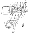
- a tractor hitch 10 comprises a frame 11 bolted to the tractor chassis 11a, a pair of lower implement support links 12 which form a unitary sub-assembly and which are received in a socket 13 mounted on frame 11, an upper implement support link 14, and two pairs of hydraulic cylinders 15 and 16 for moving the socket and hence the links 12 and 14 relative to the frame as will be described below.
- the socket 13 is mounted on frame 11 via a pair of support arms 17 which are each pivoted at one end via pins 18 to the socket and at the other end via pins 19 on to frame 11. Cylinders 15 act between the fame 11 and arms 17 via pins 20 which pass through the intermediate portions of the arms to move the socket 13 fore and aft relative to the frame 11.
- the second pair of cylinders 16 are connected with socket 13 via pins 21 and act on the frame 1 via pins 22 which connect the cylinders with a bell crank 23 which is in turn pivoted on frame 11 via pins 24. Operation of cylinder 16 raises and lowers the socket relative to the frame.
- Top link 14 is also mounted on bell crank 23 via pin 25 which passes through flanges 26.
- Bell crank 23 is connected with support arms 17 via a pair of generally horizontally extending links 27 using pins 28 and 29 respectively.
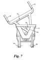
- the socket 13 is of generally triangular tapering form having a mouth 30 into which lower link sub-assembly 12 is inserted.
- Sub-assembly 12 is also of triangular form and has a pair of implement mounting hooks 31 and two side rails 32.
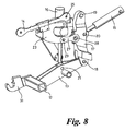
- the assembly 12 can be locked in a fully retracted position in socket 13 by a driver operated locking mechanism 35 which includes an operating lever 36 pivoted on the socket 13 by a pin 37 which extends through flanges 38.
- Lever 36 operates a latch 39 pivoted on socket 13 by pin 40 via a link 41.
- latch 39 When latch 39 is operative it engages behind a latching abutment 42 on sub-assembly 12 (see figure 5 ) to hold the assembly within the socket.
- the lever 36 is moved upwardly in the direction of arrow X to disengage latch 39 from abutment 42.
- lever 36 is also arranged to cause lever 43 attached to lever 36 to press on a surface 44 of sub- assembly 12 to ease the sub-assembly out of the socket to facilitate relative movement of the sub-assembly relative to the socket.
- the assembly 12 is manually moveable both in a fore and aft sense and a side to side sense relative to socket 13 and can also rotate within the general plane of the socket when the latch 39 is released.
- a removable stop pin 33 is provided on assembly 12 which engages in triangular opening 34 in the base of assembly 13 to prevent the complete accidental removal of sub-assembly 12 from socket 13.
- a hydraulic supply system 45 which also supplies pressurised fluid for the operation of other functions on the tractor such as normal the rear hitch etc.
- This system includes a pump 46 which supplies pressurised fluid from a reservoir 48 to a block of solenoid-operated hydraulic control valves 47 two of which (47a and 47b) are connected to cylinders 15 and 16 respectively.
- An electronic control unit 49 receives control inputs from the tractor operator from either a cab mounted pair of three-position rocker switches 50,51 or a similar pair of three position rocker switches 52,53 mounted near the front of the tractor.
- Rocker switches 50 and 52 when operated send signals to control unit 49 to command a fore or aft movement of the hitch relative to the frame 11 depending on whether portion 50a,52a or portion 50b,52b of the switch is pressed. These signals are processed by control unit 49 which in turn issues signals to cylinders 15 proportional to the operation of switches 50,52 to move support arms 17 fore or aft appropriately.
- rocker switches 51,53 sends signals to control unit 49 to command raising or lowering of the hitch relative to the frame depending on whether portion 51a,53a or portion 51b,53b of the switch is operated. These signals are processed by control unit which in turn issues signals to cylinders 16 proportional to the operation of switches 51,53 to raise or lower the socket 13 appropriately.
- the geometry of the hitch is such that when sub-assembly 12 is locked in socket 13 and socket 13 is extended by cylinders 15 the implement engaging hooks 31 at the end of top link 14 attached to the implement more substantially together.
- the link 14 is preferably of the hydraulic variable length type which includes a hydraulic cylinder 14a (see Figure 2 ).
- This variable length top link is controlled by a further rocker switch 54 in the cab and a further rocker switch 55 mounted near to the front of the tractor.
- switches have switch portions 54a and 55a which when activated hydraulically extended top link 14 and when switch portions 54b and 55b are operated reduce the length of the top link.
- Each further switch 54 and 55 activates a 4-position solenoid value 47c which admits or releases pressure from hydraulic top link 14.
- Each switch 54 and 55 has a float button 54c and 55c respectively which when activated places top link 14 in a hydraulic floating condition when its length is free to change.
- the above hitch is operated as follows to hitch-up to an implement using hooks 31 and top link 14.
- the driver positions the tractor roughly in front of the implement. He applies the hand brake, activates the front switches 52 and 53 and walks to the front of the tractor adjacent the implement. He operates switches 52 and 53 to position the hooks closer to the implement coupling bar and then unlocks the lower link sub-assembly 12 by operating lever 36 thus releasing the sub-assembly for movement relative to the socket 13 manually moves the sub-assembly 12 relative to socket 13 to couple the hooks 31 onto the implement coupling bar and operates switch position 55a to extend the top link 14 so that it can be connected to the implement. He then makes any further connections to the implement such as PTO drive and hydraulic piping connections with the implement safely coupled to the lower links and the top link.
- PTO drive and hydraulic piping connections with the implement safely coupled to the lower links and the top link.
- Float button 55c is then pressed to allow the length of the top link 14 to change in length and the sub-assembly 12 is then retracted into the socket 13 by pressing rocker switch portion 52a which extends the cylinders 15 further thus pushing sub-assembly 12 into socket 13.
- Eventually latch 39 is engaged to lock the sub-assembly 12 in socket 13. If this does not occur as a result of the operation of cylinders 15 as soon as the hitch is raised (eg by operating switch portion 53a) the sub-assembly 12 falls back into the socket 13 where it is latched by latch 39.
- the hitch therefore greatly simplifies the coupling of an implement to the tractor and avoids any need for the driver to keep leaving the tractor in order to be able to position the hitch sufficiently close to the implement for coupling to occur.
- the hitch also includes a draft force sensing system for use when using ground engaging implements.
- This sensing system is of the form described and claimed in the Applicants copending UK patent application No. 0414009.1 (Applicant's Reference 7487) which, with the hitch in as so called neutral position, only provides a draft force signal representative of the horizontal component of the forces applied to the implement by the ground. This eliminates the effect of the weight of the implement from the sensed signal which has hitherto been a problem in relation to front mounted hitches.
- This sensing system is provided by the extending cylinders 15, the pressure level in these cylinders being sensed by a pressure sensor 60 (see figure 2 ).
- This pressure signal is fed as an electrical input into a hitch control unit 61 to provide a signal proportional to the horizontal component of the force applied to the ground engaging implement hitched to links 12 and 14.
- the control unit also receives input signals from the driver via various input devices such as dials 62 and 63 for setting levels of draft force or implement position etc for the front hitch. These set values of draft force are compared with the force sensed by sensor 60 in unit 61 and an appropriate control signal is issued to valve 47b (either via control unit 49 or direct from unit 61) to raise or lower the implement to achieve the implement control setting set by the driver.
- the force sensed by sensor 60 is only representative of the horizontal component of the forces applied to the implement by the ground. This can be shown by the following analysis of the forces applied to the cylinders 15 by the hitch when it supports an implement Q as shown diagrammatically in Figure 9 .
- L3 distance "ab”since "a” is vertically above "b”
- the arrangement describe above can be modified by providing a socket cylinder 60 connected between the socket 13 and the lower link sub-assembly 12 as shown in Figure 10 .
- This cylinder 60 is pinned to the socket at 61 and to the lower link sub-assembly 12 at 62 and can be used to move the sub-assembly out of or into the socket this facilitating further the operation of coupling up an implement.
- This socket cylinder can conveniently again be controlled by a further rocker switch (not shown) on the front of the tractor.
- the front hitch can be modified by mounting the socket 13 directly on frame 11 for pivoting about pins 18 with raising cylinders 16 acting to raise and lower the socket relative to the frame and with extending cylinders 15 and support arms 17 being eliminated.
- raising cylinders 16 acting to raise and lower the socket relative to the frame and with extending cylinders 15 and support arms 17 being eliminated.
- the socket cylinder 60 of Figure 10 may also be used.
Landscapes
- Life Sciences & Earth Sciences (AREA)
- Zoology (AREA)
- Engineering & Computer Science (AREA)
- Mechanical Engineering (AREA)
- Soil Sciences (AREA)
- Environmental Sciences (AREA)
- Agricultural Machines (AREA)
Claims (23)
- Traktorfrontanbauvorrichtung (10) für die Montage eines Geräts an der Front eines Traktors, wobei die Anbauvorrichtung (10) dadurch gekennzeichnet ist, dass sie folgendes aufweist- einen einzelnen Sockel (13), der für eine Schwenkbewegung relativ zu dem Traktor montiert ist,- eine einzelne untere Verbindungsunteranordnung mit einem Paar unterer Lagerverbindungen (12) für das Gerät, wobei die Unteranordnung einen unteren Teil für eine Befestigung des Geräts und einen in dem Sockel (13) aufgenommenen inneren Teil aufweist, und- eine oder mehrere obere Lagerverbindungen (14) für das Gerät, die durch den Traktor gestützt sind,- wobei die untere Verbindungsunteranordnung (12) relativ zu dem Sockel (13) zwischen einer Kopplungsposition, in der die untere Verbindungsunteranordnung (12) zur Vereinfachung der Verbindung des Geräts mit den unteren Lagerverbindungen (12) für das Gerät zumindest teilweise aus dem Sockel (13) zurückziehbar ist, und einer blockierten Betriebsstellung des Geräts, in der die untere Verbindungsunteranordnung in dem Sockel (13) blockiert ist, verschwenkbar ist.
- Anbauvorrichtung nach Anspruch 1, dadurch gekennzeichnet, dass der Sockel (13) und die obere Lagerverbindung (14) oder die oberen Lagerverbindungen (14) auf einem Rahmen (11) montiert sind, der von dem Traktor getragen wird.
- Anbauvorrichtung nach Anspruch 2, dadurch gekennzeichnet, dass ein Ausfahrmittel (15) bereitgestellt ist, um den Sockel (13) im Wesentlichen horizontal zu dem Rahmen (11) zwischen der blockierten Betriebsstellung des Geräts und der Kopplungsstellung zu bewegen.
- Anbauvorrichtung nach einem der Ansprüche 1 bis 3, dadurch gekennzeichnet, dass der Sockel (13) eine sich verjüngende Form besitzt, die an ihrer Mündung (30) am weitesten ist, und dass die untere Verbindungsunteranordnung (12) eine entsprechende sich verjüngende Form besitzt.
- Anbauvorrichtung nach Anspruch 1 oder 2, dadurch gekennzeichnet, dass die Unteranordnung zur Vereinfachung des Anbaus vor und zurück sowie seitlich relativ zu dem Sockel (13) bewegbar und auch in der Hauptebene des Sockels (13) drehbar ist, wenn die untere Verbindungsunteranordnung (12) teilweise aus dem Sockel (13) zurückgezogen ist.
- Anbauvorrichtung nach einem der Ansprüche 1 bis 5, dadurch gekennzeichnet, dass die Unteranordnung (12) ein lösbares Stoppmittel (33) besitzt, welches mit dem Sockel (13, 34) zusammenarbeitet, um zu verhindern, dass die Unteranordnung unbeabsichtigterweise vollständig aus dem Sockel zurückgezogen wird.
- Anbauvorrichtung nach einem der Ansprüche 1 bis 6, dadurch gekennzeichnet, dass der Sockel (13) ein vom Bediener geregeltes Blockiermittel (35) zum Blockieren der Unteranordnung (12) in dem Sockel (13) aufweist.
- Anbauvorrichtung nach Anspruch 7, dadurch gekennzeichnet, dass das Blockiermittel (35, 36, 43) auch die untere Verbindungsunteranordnung (12) teilweise aus dem Sockel (13) heraus bewegt.
- Anbauvorrichtung nach einem der Ansprüche 1 bis 8, dadurch gekennzeichnet, dass ein hydraulischer Sockelzylinder (60) bereitgestellt ist, um die untere Verbindungsunteranordnung (12) relativ zu dem Sockel (13) zu bewegen.
- Anbauvorrichtung nach Anspruch 3, dadurch gekennzeichnet, dass das Ausfahrmittel ein hydraulisches Zylindermittel (15) aufweist, welches zwischen dem Sockel (13) und dem Rahmen (11) wirksam ist.
- Anbauvorrichtung nach einem der Ansprüche 1 bis 10, dadurch gekennzeichnet, dass ein Hebemittel (16) zwischen dem Sockel (13) und dem Traktor wirksam ist, um den Sockel (13) um eine erste im Wesentlichen horizontale Querachse (18) zu verschwenken, um den Sockel (13) und somit die untere Verbindungsanordnung (12) relativ zu dem Traktor anzuheben und abzusenken.
- Anbauvorrichtung nach Anspruch 3 und 11, dadurch gekennzeichnet, dass der Sockel (13) an einem Ende eines Paars von Stützelementen (17) für eine Schwenkbewegung um die erste im Wesentlichen horizontale Querachse (18) montiert ist, wobei das andere Ende der Stützelemente (17) um eine zweite im Wesentlichen horizontale Querachse (19) an dem Rahmen (11) verschwenkt wird, wobei das Ausfahrmittel (15) so zwischen dem Rahmen (11) und einem Teil (20) der Stützelemente (17) zwischen deren Enden wirksam ist, dass eine Betätigung des Ausfahrmittels (15) die Stützelemente (17) in einer Vorwärts- und Rückwärtsrichtung relativ zu dem Rahmen (11) um die zweite Achse (19) verschwenkt, um den Sockel (13) zwischen seiner zurückgezogenen und seiner ausgefahrenen Stellung zu bewegen.
- Anbauvorrichtung nach Anspruch 11 und 12, dadurch gekennzeichnet, dass das Hebemittel (16) über einen Dreibinder (23) auf den Rahmen (11) einwirkt, wobei die obere Lagerverbindung (14) oder jede der oberen Lagerverbindungen (14) für das Gerät ebenfalls mit dem Dreibinder (23) verbunden sind.
- Anbauvorrichtung nach Anspruch 13, dadurch gekennzeichnet, dass der Dreibinder (23) durch ein sich im Wesentlichen horizontal erstreckendes Verbindungsmittel (27) auch mit den Stützelementen (17) verbunden ist.
- Anbauvorrichtung nach einem der Ansprüche 11 bis 14, dadurch gekennzeichnet, dass das Hebemittel (16) weiterhin ein hydraulisches Zylindermittel (16) aufweist, welches zwischen dem Sockel (13) und dem Rahmen (11) wirksam ist.
- Anbauvorrichtung nach einem der Ansprüche 9 bis 15, dadurch gekennzeichnet, dass die Bedienerregelmittel (52, 53) für das Ausfahrmittel (15) und das Hebemittel (16) an der Front des Traktors vorgesehen sind.
- Anbauvorrichtung nach Anspruch 9, dadurch gekennzeichnet, dass die vom Bediener geregelten Mittel (52, 53) für den Sockelzylinder (60) an der Front des Traktors vorgesehen sind.
- Anbauvorrichtung nach einem der Ansprüche 1 bis 17, dadurch gekennzeichnet, dass die oder jede obere Lagerverbindung (14) für das Gerät in der Länge hydraulisch (14a) ausgefahren oder zurückgezogen werden kann.
- Anbauvorrichtung nach Anspruch 18, dadurch gekennzeichnet, dass die vom Bediener geregelten Mittel (55) zum Ausfahren oder Zurückziehen der oder jeder Lagerverbindung (14) für das Gerät an der Front des Traktors vorgesehen sind.
- Anbauvorrichtung nach einem der Ansprüche 11 bis 19, dadurch gekennzeichnet, dass das Heben (16) des Sockels (13) nach dem Verbinden der ausgefahrenen unteren Verbindungen mit einem Gerät dazu führt, dass sich die Unteranordnung (12) mit dem verbundenen Gerät in ihre zurückgezogene Stellung in dem Sockel (13) bewegt.
- Anbauvorrichtung nach einem der Ansprüche 11 bis 20 für eine Verwendung mit einem Boden bearbeitenden Gerät (Q), wobei ein Messsystem bereitgestellt ist, welches ein lediglich die horizontale Komponente (Gx) der durch den Boden auf das Gerät aufgebrachten Kräfte angebendes Signal bereitstellt, wodurch der Effekt des Gewichts des Geräts aus dem gemessenen Signal entfernt wird, und wobei ein Regelmittel (61) bereitgestellt ist, welches ein sich auf den gewünschten Betriebszustand des Geräts beziehendes Signal von dem Messsystem (15, 60) und von dem Bediener des Traktors (62, 63) empfängt, und welches diese Signale vergleicht, um dem Hebemittel (16) für die Einstellung der Arbeitsstellung des Geräts (Q) ein Ausgangssignal bereitzustellen, um den gewünschten Betriebszustand des Geräts zu erreichen.
- Anbauvorrichtung nach Anspruch 12 und 21, dadurch gekennzeichnet, dass das Messsystem einen mit dem mittleren Teil (20) der Stützelemente (17) verbundenen Sensor (15, 60) aufweist und die Geometrie der Verbindungen zwischen den Komponenten (17, 23, 27) der Anbauvorrichtung so gewählt ist, dass nur die horizontale Komponente (Gx) der von dem Gerät auf die oberen (14) und unteren (12) Verbindungen ausgeübten Kräfte über das Anbaugerät an den Sensor (15, 15) übertragen wird, wenn sich die Anbauvorrichtung in einer neutralen Arbeitsstellung befindet, in der das Hebemittel (16) vertikal und das Verbindungsmittel (12) horizontal wirksam ist.
- Anbauvorrichtung nach Anspruch 22, dieser wiederum nach Anspruch 12, dadurch gekennzeichnet, dass das Druckniveau in dem hydraulischen Zylindermittel (15) der Ausfahrmittel als Angabe des Niveaus der horizontalen Komponente (Gx) der auf das Gerät (Q) wirkenden Kräfte verwendet wird.
Applications Claiming Priority (2)
| Application Number | Priority Date | Filing Date | Title |
|---|---|---|---|
| GB0414011 | 2004-06-22 | ||
| GB0414011A GB2415354A (en) | 2004-06-22 | 2004-06-22 | Tractor front hitch |
Publications (2)
| Publication Number | Publication Date |
|---|---|
| EP1609345A1 EP1609345A1 (de) | 2005-12-28 |
| EP1609345B1 true EP1609345B1 (de) | 2008-04-09 |
Family
ID=32799991
Family Applications (1)
| Application Number | Title | Priority Date | Filing Date |
|---|---|---|---|
| EP05013214A Expired - Lifetime EP1609345B1 (de) | 2004-06-22 | 2005-06-20 | Traktorfrontanbauvorrichtung |
Country Status (4)
| Country | Link |
|---|---|
| US (1) | US7600574B2 (de) |
| EP (1) | EP1609345B1 (de) |
| DE (1) | DE602005005899T2 (de) |
| GB (1) | GB2415354A (de) |
Cited By (6)
| Publication number | Priority date | Publication date | Assignee | Title |
|---|---|---|---|---|
| US10670479B2 (en) | 2018-02-27 | 2020-06-02 | Methode Electronics, Inc. | Towing systems and methods using magnetic field sensing |
| US10696109B2 (en) | 2017-03-22 | 2020-06-30 | Methode Electronics Malta Ltd. | Magnetolastic based sensor assembly |
| US11084342B2 (en) | 2018-02-27 | 2021-08-10 | Methode Electronics, Inc. | Towing systems and methods using magnetic field sensing |
| US11135882B2 (en) | 2018-02-27 | 2021-10-05 | Methode Electronics, Inc. | Towing systems and methods using magnetic field sensing |
| US11221262B2 (en) | 2018-02-27 | 2022-01-11 | Methode Electronics, Inc. | Towing systems and methods using magnetic field sensing |
| US11491832B2 (en) | 2018-02-27 | 2022-11-08 | Methode Electronics, Inc. | Towing systems and methods using magnetic field sensing |
Families Citing this family (21)
| Publication number | Priority date | Publication date | Assignee | Title |
|---|---|---|---|---|
| JP4578410B2 (ja) * | 2006-01-16 | 2010-11-10 | ヤンマー株式会社 | 作業車両のフロントガード |
| FI20065658A0 (fi) * | 2006-10-16 | 2006-10-16 | Lh Lift Oy | Etunostolaite |
| GB0723993D0 (en) * | 2007-12-08 | 2008-01-16 | Agco Sa | Implement control system |
| US8256526B2 (en) * | 2008-07-08 | 2012-09-04 | A.I.L., Inc. | Apparatus and a system for providing guidance control for pull type tongued implements |
| US20110180282A1 (en) * | 2010-01-26 | 2011-07-28 | Degelman Industries Ltd. | Wrap around dozer blade hitch |
| US8353359B2 (en) * | 2010-10-08 | 2013-01-15 | Amerequip Corporation | Apparatus and method for attaching a utility vehicle 3-point hitch to an implement bracket |
| US8555995B2 (en) * | 2010-12-03 | 2013-10-15 | Jerry Harris | Three-point front hitch mountable to the frame of an agricultural tractor |
| GB201020863D0 (en) * | 2010-12-09 | 2011-01-26 | Agco Internat Ltd | Linkage rocker arm on an agricultural vehicle |
| US8696024B2 (en) | 2011-12-08 | 2014-04-15 | La Compagnie Normand Ltee | Coupler for a vehicle and a vehicle comprising same |
| US10356971B2 (en) | 2015-09-23 | 2019-07-23 | Deere & Company | Front attachment lift mechanism |
| US9930833B2 (en) | 2016-03-22 | 2018-04-03 | Cnh Industrial America Llc | Tilt cylinder remote attachment apparatus |
| US9567018B1 (en) * | 2016-09-02 | 2017-02-14 | Equipement Vtc Mfg Inc. | Tractor front linkage quick attach coupling system |
| FI127278B (fi) * | 2016-10-05 | 2018-02-28 | Lh Lift Oy | Työkoneen etunostolaite ja työkone |
| US11027787B2 (en) | 2017-10-31 | 2021-06-08 | Deere & Company | Attachment assembly for use with a work machine |
| US11014417B2 (en) | 2018-02-27 | 2021-05-25 | Methode Electronics, Inc. | Towing systems and methods using magnetic field sensing |
| WO2020081111A1 (en) * | 2018-10-19 | 2020-04-23 | Cowley Daniel J | Mechanism combining articulation and side-shift |
| US11606894B2 (en) | 2019-05-28 | 2023-03-21 | Copperhead Planter Products, Llc | Implement guidance module |
| US11267300B2 (en) * | 2019-06-26 | 2022-03-08 | Deere & Company | Hitch mechanism |
| GB201909473D0 (en) | 2019-07-01 | 2019-08-14 | Agco Int Gmbh | Implement hitch control system |
| GB201909474D0 (en) * | 2019-07-01 | 2019-08-14 | Agco Int Gmbh | Implement hitch control system |
| EP4706364A1 (de) | 2024-09-09 | 2026-03-11 | AGCO International GmbH | Eingabevorrichtung mit ober- und unterrad zur steuerung einer landwirtschaftlichen maschine |
Family Cites Families (26)
| Publication number | Priority date | Publication date | Assignee | Title |
|---|---|---|---|---|
| US3128830A (en) * | 1964-04-14 | Draft sensing tractor implement hitch | ||
| DE1457677C2 (de) * | 1965-12-17 | 1973-01-04 | Deere & Co., Moline, Ill. (V.St.A.) | Kupplungsvorrichtung zum Anschließen von Anbaugeräten an das Dreipunktgestänge von Schleppern |
| US3432184A (en) * | 1967-07-10 | 1969-03-11 | United States Steel Corp | Power actuated tractor hitch |
| US3561789A (en) * | 1968-11-22 | 1971-02-09 | Allis Chalmers Mfg Co | Tractor hitch |
| US3520369A (en) * | 1969-02-27 | 1970-07-14 | Int Harvester Co | Resilient draft sensing device |
| FR2061572B1 (de) * | 1969-07-25 | 1973-03-16 | Renault | |
| US3876092A (en) * | 1974-07-26 | 1975-04-08 | Rivinius Inc | Implement connecting coupler mechanism |
| US4425970A (en) * | 1981-09-21 | 1984-01-17 | Massey-Ferguson Inc. | Tractor draft sensing apparatus |
| EP0132428A1 (de) * | 1982-12-22 | 1985-02-06 | Släpvagnskopplingar Ab | Karren |
| US4515387A (en) * | 1983-03-25 | 1985-05-07 | Schuck Howard L | Hitch with swiveling tongue |
| DE3512428A1 (de) * | 1985-04-04 | 1986-10-16 | Deere & Co., Moline, Ill., US, Niederlassung Deere & Co. European Office, 6800 Mannheim | Laengenveraenderliche hubstrebe |
| GB2178290A (en) * | 1985-07-02 | 1987-02-11 | Christopher Edward Meddins | Implement mounting attachment |
| US4778195A (en) * | 1987-03-02 | 1988-10-18 | Bertrand Vachon | Tractor work implement coupler |
| GB8914927D0 (en) * | 1989-06-29 | 1989-08-23 | Steelfab Ltd | Implement attachment coupler |
| US5082065A (en) * | 1990-08-15 | 1992-01-21 | Support Services International, Inc. | Quick attach implement coupler |
| US5538086A (en) * | 1994-12-27 | 1996-07-23 | Wright; Rocky A. | Variable orientation attachment implement |
| US5697454A (en) * | 1995-07-18 | 1997-12-16 | Wilcox Brothers Incorporated | Three-point hitch assembly |
| US5997024A (en) * | 1998-04-07 | 1999-12-07 | Deere & Company | Hitch mechanism |
| US6148927A (en) * | 1998-08-21 | 2000-11-21 | Hoffart; Ronald J. | Adjustable three-point hitch |
| FR2789846B1 (fr) * | 1999-02-23 | 2001-05-11 | Altec | Dispositif de relevage destine a etre monte a l'avant ou a l'arriere d'un engin notamment agricole en vue de l'attelage d'un outil |
| US6227304B1 (en) * | 1999-03-01 | 2001-05-08 | Case Corporation | Upper hitch link |
| DE19951840B4 (de) * | 1999-10-28 | 2009-01-08 | Deere & Company, Moline | Anbauschnittstelle zur Kopplung von Arbeitsgeräten an ein Arbeitsfahrzeug |
| US6431288B1 (en) * | 2000-11-21 | 2002-08-13 | Ronald J. Hoffart | Front three-point hitch system |
| US6478094B2 (en) * | 2001-04-10 | 2002-11-12 | Frank David Alexander | Hydraulic three point tractor hitch |
| US6830112B2 (en) * | 2001-10-26 | 2004-12-14 | Mtd Products Inc | Front hitch system |
| US6510628B1 (en) * | 2001-10-31 | 2003-01-28 | Caterpillar Inc | Method and apparatus for determining a contact force of a work tool |
-
2004
- 2004-06-22 GB GB0414011A patent/GB2415354A/en not_active Withdrawn
-
2005
- 2005-06-20 DE DE602005005899T patent/DE602005005899T2/de not_active Expired - Lifetime
- 2005-06-20 EP EP05013214A patent/EP1609345B1/de not_active Expired - Lifetime
- 2005-06-21 US US11/157,470 patent/US7600574B2/en not_active Expired - Fee Related
Cited By (7)
| Publication number | Priority date | Publication date | Assignee | Title |
|---|---|---|---|---|
| US10696109B2 (en) | 2017-03-22 | 2020-06-30 | Methode Electronics Malta Ltd. | Magnetolastic based sensor assembly |
| US10940726B2 (en) | 2017-03-22 | 2021-03-09 | Methode Electronics Malta Ltd. | Magnetoelastic based sensor assembly |
| US10670479B2 (en) | 2018-02-27 | 2020-06-02 | Methode Electronics, Inc. | Towing systems and methods using magnetic field sensing |
| US11084342B2 (en) | 2018-02-27 | 2021-08-10 | Methode Electronics, Inc. | Towing systems and methods using magnetic field sensing |
| US11135882B2 (en) | 2018-02-27 | 2021-10-05 | Methode Electronics, Inc. | Towing systems and methods using magnetic field sensing |
| US11221262B2 (en) | 2018-02-27 | 2022-01-11 | Methode Electronics, Inc. | Towing systems and methods using magnetic field sensing |
| US11491832B2 (en) | 2018-02-27 | 2022-11-08 | Methode Electronics, Inc. | Towing systems and methods using magnetic field sensing |
Also Published As
| Publication number | Publication date |
|---|---|
| DE602005005899T2 (de) | 2009-06-10 |
| DE602005005899D1 (de) | 2008-05-21 |
| EP1609345A1 (de) | 2005-12-28 |
| GB2415354A (en) | 2005-12-28 |
| US20060016611A1 (en) | 2006-01-26 |
| GB0414011D0 (en) | 2004-07-28 |
| US7600574B2 (en) | 2009-10-13 |
Similar Documents
| Publication | Publication Date | Title |
|---|---|---|
| EP1609345B1 (de) | Traktorfrontanbauvorrichtung | |
| CA2063099C (en) | Interface system for a towed implement | |
| US4477101A (en) | Arrangement for coupling an implement to a tractor | |
| US6035943A (en) | Frame leveling system for tillage implements | |
| US4193458A (en) | Tractor and implement and hydraulic system therefor | |
| US5692573A (en) | Towing Arrangement | |
| SU1286101A3 (ru) | Механизм креплени дл зацеплени землеобрабатывающего оборудовани к т гачу | |
| EP0617881B1 (de) | Vorrichtung zum Verbinden eines Gerätes mit einem ziehenden Fahrzeug | |
| US4324296A (en) | Multi-section agricultural implement including latch assembly therefor | |
| US5092409A (en) | Coupling and lifting system for an implement, in particular an agricultural implement, that can be mounted on the front of a tractor | |
| US6105679A (en) | Control system for a hitched or trailed implement | |
| US6773223B2 (en) | Hydraulic attachment latch mechanism for skid steer loader | |
| AU613826B2 (en) | Hitch control system with start-up lock-out | |
| US3463510A (en) | Tractor-implement weight-transfer draft system | |
| US20080066934A1 (en) | Implement/hitch draft control using hitch cylinder pressure as load feedback | |
| US3731745A (en) | Combined draft hook operating and draft sensing | |
| US4805322A (en) | Excavating blade assembly | |
| EP0138519A2 (de) | Zugvorrichtungen | |
| EP1103171A1 (de) | Schlepperkupplung | |
| US4103796A (en) | Bucket attachment for tractors | |
| GB2479890A (en) | Three point coupler | |
| US2752836A (en) | Tractor implement hitch | |
| US3463511A (en) | Weight-transfer hitch | |
| EP2540149A1 (de) | Traktorwerkzeuganbauvorrichtung | |
| US4331347A (en) | Three-point hookup apparatus |
Legal Events
| Date | Code | Title | Description |
|---|---|---|---|
| PUAI | Public reference made under article 153(3) epc to a published international application that has entered the european phase |
Free format text: ORIGINAL CODE: 0009012 |
|
| AK | Designated contracting states |
Kind code of ref document: A1 Designated state(s): AT BE BG CH CY CZ DE DK EE ES FI FR GB GR HU IE IS IT LI LT LU MC NL PL PT RO SE SI SK TR |
|
| AX | Request for extension of the european patent |
Extension state: AL BA HR LV MK YU |
|
| 17P | Request for examination filed |
Effective date: 20060628 |
|
| AKX | Designation fees paid |
Designated state(s): DE FR GB IT |
|
| 17Q | First examination report despatched |
Effective date: 20070309 |
|
| GRAP | Despatch of communication of intention to grant a patent |
Free format text: ORIGINAL CODE: EPIDOSNIGR1 |
|
| GRAS | Grant fee paid |
Free format text: ORIGINAL CODE: EPIDOSNIGR3 |
|
| GRAA | (expected) grant |
Free format text: ORIGINAL CODE: 0009210 |
|
| AK | Designated contracting states |
Kind code of ref document: B1 Designated state(s): DE FR GB IT |
|
| REG | Reference to a national code |
Ref country code: GB Ref legal event code: FG4D |
|
| REF | Corresponds to: |
Ref document number: 602005005899 Country of ref document: DE Date of ref document: 20080521 Kind code of ref document: P |
|
| ET | Fr: translation filed | ||
| PLBE | No opposition filed within time limit |
Free format text: ORIGINAL CODE: 0009261 |
|
| STAA | Information on the status of an ep patent application or granted ep patent |
Free format text: STATUS: NO OPPOSITION FILED WITHIN TIME LIMIT |
|
| 26N | No opposition filed |
Effective date: 20090112 |
|
| REG | Reference to a national code |
Ref country code: FR Ref legal event code: PLFP Year of fee payment: 11 |
|
| PGFP | Annual fee paid to national office [announced via postgrant information from national office to epo] |
Ref country code: DE Payment date: 20150619 Year of fee payment: 11 Ref country code: GB Payment date: 20150618 Year of fee payment: 11 |
|
| PGFP | Annual fee paid to national office [announced via postgrant information from national office to epo] |
Ref country code: FR Payment date: 20150619 Year of fee payment: 11 Ref country code: IT Payment date: 20150623 Year of fee payment: 11 |
|
| REG | Reference to a national code |
Ref country code: DE Ref legal event code: R119 Ref document number: 602005005899 Country of ref document: DE |
|
| GBPC | Gb: european patent ceased through non-payment of renewal fee |
Effective date: 20160620 |
|
| REG | Reference to a national code |
Ref country code: FR Ref legal event code: ST Effective date: 20170228 |
|
| PG25 | Lapsed in a contracting state [announced via postgrant information from national office to epo] |
Ref country code: FR Free format text: LAPSE BECAUSE OF NON-PAYMENT OF DUE FEES Effective date: 20160630 Ref country code: DE Free format text: LAPSE BECAUSE OF NON-PAYMENT OF DUE FEES Effective date: 20170103 |
|
| PG25 | Lapsed in a contracting state [announced via postgrant information from national office to epo] |
Ref country code: GB Free format text: LAPSE BECAUSE OF NON-PAYMENT OF DUE FEES Effective date: 20160620 |
|
| PG25 | Lapsed in a contracting state [announced via postgrant information from national office to epo] |
Ref country code: IT Free format text: LAPSE BECAUSE OF NON-PAYMENT OF DUE FEES Effective date: 20160620 |