EP1609392A1 - Schienenbefestigungsteilstruktur - Google Patents
Schienenbefestigungsteilstruktur Download PDFInfo
- Publication number
- EP1609392A1 EP1609392A1 EP04722070A EP04722070A EP1609392A1 EP 1609392 A1 EP1609392 A1 EP 1609392A1 EP 04722070 A EP04722070 A EP 04722070A EP 04722070 A EP04722070 A EP 04722070A EP 1609392 A1 EP1609392 A1 EP 1609392A1
- Authority
- EP
- European Patent Office
- Prior art keywords
- above described
- drawer
- rail
- flange
- ribs
- Prior art date
- Legal status (The legal status is an assumption and is not a legal conclusion. Google has not performed a legal analysis and makes no representation as to the accuracy of the status listed.)
- Withdrawn
Links
Images


Classifications
-
- A—HUMAN NECESSITIES
- A47—FURNITURE; DOMESTIC ARTICLES OR APPLIANCES; COFFEE MILLS; SPICE MILLS; SUCTION CLEANERS IN GENERAL
- A47B—TABLES; DESKS; OFFICE FURNITURE; CABINETS; DRAWERS; GENERAL DETAILS OF FURNITURE
- A47B67/00—Chests; Dressing-tables; Medicine cabinets or the like; Cabinets characterised by the arrangement of drawers
- A47B67/04—Chests of drawers; Cabinets characterised by the arrangement of drawers
-
- A—HUMAN NECESSITIES
- A47—FURNITURE; DOMESTIC ARTICLES OR APPLIANCES; COFFEE MILLS; SPICE MILLS; SUCTION CLEANERS IN GENERAL
- A47B—TABLES; DESKS; OFFICE FURNITURE; CABINETS; DRAWERS; GENERAL DETAILS OF FURNITURE
- A47B88/00—Drawers for tables, cabinets or like furniture; Guides for drawers
- A47B88/40—Sliding drawers; Slides or guides therefor
- A47B88/423—Fastening devices for slides or guides
- A47B88/427—Fastening devices for slides or guides at drawer side
Definitions
- the present invention relates to a rail fixing part structure of a drawer that houses clothing and the like.
- chests are used on an occasion of housing clothing and the like.
- the chest is constructedby a chest bodymade of a synthetic resin and a drawer made of a synthetic resin which is housed in the chest body to be able to be drawn.
- a drawer part supported by the chest body is constructed by a metal rail.
- the present invention is made in view of the above conventional problems, and an object of the present invention is to provide a rail fixing part structure easy in mounting operation.
- a flange which extends toward the aforesaid drawer, is provided at the aforesaid rail, while ribs which vertically sandwich the aforesaid flange are provided at a side surface of the aforesaid drawer.
- the flange provided at the rail is inserted between the ribs which are provided at the flange, and the above described flange is vertically sandwiched with the ribs. Thereby, the above described rail is locked at the drawer.
- a support surface which extends along the aforesaid flange is provided at an upper end portion of the rib which supports a lower surface of the aforesaid flange.
- the support surface which extends along the above described flange is provided at the upper end portion of the rib which supports the lower surface of the above described flange.
- a screw-in part in which a screw that is inserted through the aforesaid flange is screwed in the state in which the aforesaid flange of the aforesaid rail is sandwiched between the aforesaid ribs is provided at the aforesaid drawer.
- the drawer is provided with the screw-in part in which the screw inserted through the above described flange is screwed is provided, and by screwing the above described screw into the above described screw-in part, the flange of the above described rail is fixed in the state in which the flange is sandwiched with the ribs of the drawer.
- FIG. 1 is a front view showing one embodiment of the present invention.
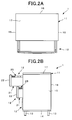
- FIG. 2A is a plane view of the same embodiment.
- FIG. 2B is a side view.
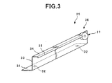
- FIG. 3 is a perspective view showing a rail in the same embodiment.
- FIG. 4 is a side view showing a drawer body in the same embodiment.
- FIG. 5 is a side view showing a section of a folded part of the drawer body in the same embodiment.
- Fig. 1 is a view showing a chest 1 including a rail fixing part structure according to an embodiment, and the chest 1 houses clothing and the like.
- the chest 1 is constructed by a wooden chest body 11 and drawings 12 made of a synthetic resin.
- the above described chest body 11 is formed into a rectangular shape by a bottom plate 14 provided with leg parts 13, side plates 15 and 15 vertically provided at both side portions of the bottom plate 14, a back plate 16 vertically provided at a back side of the above described bottom plate 14, a top plate 17 provided at an upper end of the above described side plates 15 and 15, and the above described back plate 16, as shown in Fig. 1 and Fig. 2.
- Three of the above described drawers 12 are housed in a front opening of the chest body 11 to be able to be drawn, and are constructed to be able to house and store material goods in the drawers 12.
- the above described drawer 12 is constructed by a drawer body 21 in a rectangular container shape, and a front plate 22 mounted in the state in which it is locked at claw parts 21a and 21a (see Fig. 4) of the drawer body 21, and the above described drawer body 21 and the above described front plate 22 are formed to be semitransparent and constructed to be able to confirm an inside.
- the front plate 22 is formed to be light blue and transparent, and the above described drawer body 21 is formed to be white and transparent.
- the above described front plate 22 and the drawer body 21 may be formed to be not only semitransparent but also formed to be transparent, or opaque, and in the case of opaque, they can be also colored.
- the above described front plate 22 and the above described drawer body 21 are constructed by separate pieces, and therefore, the above described front plate 22 and the above described drawer body 21 can be set to be the same color, or can be set to be different colors. As a result, the appearance quality can be enhanced and variation can be increased.
- a recessed part 23 is provided at a lower portion of the above described front plate 22, and a step part 24 on which a hand can be laid at the time of drawing is formed between the recessed part 23 and the ordinary part.
- the step part 24 is formed into a bow shape with a central portion projecting upward, and the operating force applied to the step part 24 is applied to a later-described rail 25 which supports the drawer 12 at the chest body 11.
- Metal rails 25, which are supported at a rail not shown provided at an inner surface of each of the side plates 15 and 15 of the above described chest body 11 and slidably support the drawer 12 at the above described chest body 11, are fixed to both side portions of the above described drawer body 21, and the drawer body 21 opened upward has its upper end portion reinforced by the rails 25.
- the rail 25 is formed by folding a long metal plate, and a flange 31 extending toward the above described drawer 12 is provided at the lower edge portion, as shown in Fig. 3. Screw insertion holes 32 and 32 are provided at both endportions of the flange 31 and a raised wall 33 rises from the side edge of the flange 31.
- a guide surface 34 extending in the direction to separate from the above described drawer 12 is provided at an upper edge of the raised wall 33, and a bent part 35 which is bent downward is formed at a side edge of the guide surface 34.
- the above described guide surface 34 is notched at one end portion of the rail 25, and a roller 37 a part of which projects from the above described guide surface 34 is rotatably supported at a region of the above described raised wall 33 in a notched part 36.
- the above described drawer body 21 is formed to be opened upward by a rectangular bottom surface 41, a front surface 42 raised from a front edge of the bottom surface 41, side surfaces 43 raised from both side edges of the above described bottom surface 41, and a back surface 44 raised from a rear edge of the above described bottom surface 41.
- an outward extending surface 45 which extends to an outside is formed at upper edges of the above described side surface 43 and the above described back surface 44, and a downward extending surface 46 which extends downward is formed at the extending surface 45.
- the downward extending surface 46 is constructed to be in surface contact with the raisedwall 33 of the mounted rail 25 to prevent tilt of the rail 25 and form a folded portion at the upper edge portions of the above described side surfaces 43 and the above described back surface 44 to be able to reinforce them.
- the folded portion is constituted of side folded portions 51 formed at the above described both side surfaces 43, and a rear folded part 52 formed over the back surface 44 from the rear portions of both the side surfaces 43, and gaps 53 are formed between the above described both side folded portions 51 and the above described rear folded part 52.
- upper ribs 54 and 54 extending downward from the above described outward extending surfaces 45 and 45 are formed at both ends of the above described side folded parts 51 and both ends of the above described rear folded part 52, and the upper ribs 54 and 54 are also provided to connect to the above described side surfaces 43.
- a lower rib 55 extending in the vertical direction is formed at a lower portion of the above described gap 53 between the above described side folded part 51 and the above described rear folded part 52, and on the front surface 42 side from the above described side folded part 51, the lower rib 55 extending in the vertical direction is formed.
- Upper ends of both the lower ribs 55 and 55 are provided at a lower position from the position of the height of the lower end of the above described upper rib 54, so that the flange 31 of the above described rail 25 can be vertically sandwiched with the above described upper ribs 54 and the lower ribs 55.
- Support surfaces 61 which extend along the above described flange 31 are integrally formed at upper end portions of the above described lower ribs 55 which support the above described flange 31 from the lower surface side, and the support surface 61 is constructed to be in surface contact with the lower surface of the above described flange 31.
- cylindrical screw-in parts 71 which extend downward are integrally formed at both end portions at the above described outward extending surfaces 45 of the above described both side folded parts 51 and 51.
- the screw-in parts 71 are provided at positions corresponding to screw insertion holes 32 and 32 formed at the above described flange 31 in the state in which the above described rail 25 is mounted, and the lower end of the screw-in part 71 is set to have a length dimension that reaches the top surface of the above described flange 31.
- tapping screws which are inserted through the above described screw insertion holes 32 and 32 of the above described flange 31 can be screwed into the above described screw-in parts 71 and 71 in the state in which the above described flange 31 of the above described rail 25 is sandwiched between the above described respective ribs 54 and 55.
- the flange 31 provided at the rail 25 is inserted between the upper ribs 54 and the lower ribs 55 provided at the drawer 12, and the above described flange 31 is vertically sandwiched with both the ribs 54 and 55. Thereby, the above described rail 25 is locked at the drawer 12.
- the above described rail 25 can be locked at the drawer 12 in the state in which the above described flange 31 is vertically sandwiched between both the ribs 54 and 55. Thereby, the metal rail 25 can be easily mounted to the drawer 12 of the synthetic resin, and the mounting operation can be easily performed.
- the support surfaces 61 which extend along the above described flange 31 is provided at the upper end portions of the lower ribs 55 which support the lower surface of the above described flange 31.
- the screw-in parts 71 which extend downward are integrally formed at both end portions at the outward extending surfaces 45 of the both side folded parts 51 and 51 of the above described drawer 12, and the screw-in parts 71 and 71 are provided at the positions corresponding to the screw insertion holes 32 and 32 of the above described rail 25.
- the tapping screws are inserted through the screw insertion holes 32 and 32 of the above described flange 31 in the state in which the flange 31 of the above described rail 25 is sandwiched between the respective ribs 54 and 55, and the tapping screws are screwed into the above described screw-in parts 71 and 71, whereby the flange 31 of the above described rail 25 can be screwed in the state in which the flange 31 is sandwiched between the respective ribs 54 and 55 of the above described drawer 12. Thereby, fixation can be further enhanced.
- the flange provided at the rail is inserted into the ribs provided at the drawer, whereby the rail can be locked at the drawer in the state in which the above described flange is vertically sandwiched with the ribs.
- the metal rail can be easily mounted to the drawer of the synthetic resin, and the mounting operation can be easily performed.
- the support surfaces which extend along the above described flange are provided at the upper end portions of the ribs which support the lower surface of the above described flange, and therefore, the fixed state of the flange can be further stabilized.
- the screw-in parts in which the screws inserted through the flange are screwed are provided at the drawer, and the flange of the above described rail can be fixed in the state in which the flange is sandwiched between the ribs of the drawer by screwing the above described screws into the above described screw-in parts. Thereby, fixation can be enhanced.
Landscapes
- Drawers Of Furniture (AREA)
Applications Claiming Priority (3)
| Application Number | Priority Date | Filing Date | Title |
|---|---|---|---|
| JP2003077191A JP4102227B2 (ja) | 2003-03-20 | 2003-03-20 | レール固定部構造 |
| JP2003077191 | 2003-03-20 | ||
| PCT/JP2004/003749 WO2004082432A1 (ja) | 2003-03-20 | 2004-03-19 | レール固定部構造 |
Publications (2)
| Publication Number | Publication Date |
|---|---|
| EP1609392A1 true EP1609392A1 (de) | 2005-12-28 |
| EP1609392A4 EP1609392A4 (de) | 2006-10-18 |
Family
ID=33027939
Family Applications (1)
| Application Number | Title | Priority Date | Filing Date |
|---|---|---|---|
| EP04722070A Withdrawn EP1609392A4 (de) | 2003-03-20 | 2004-03-19 | Schienenbefestigungsteilstruktur |
Country Status (6)
| Country | Link |
|---|---|
| US (1) | US20070007869A1 (de) |
| EP (1) | EP1609392A4 (de) |
| JP (1) | JP4102227B2 (de) |
| KR (1) | KR20050107519A (de) |
| CN (1) | CN100415142C (de) |
| WO (1) | WO2004082432A1 (de) |
Families Citing this family (12)
| Publication number | Priority date | Publication date | Assignee | Title |
|---|---|---|---|---|
| JP5053534B2 (ja) * | 2005-10-20 | 2012-10-17 | アイリスオーヤマ株式会社 | チェスト |
| USD615327S1 (en) * | 2008-02-22 | 2010-05-11 | Harn Marketing Sdn. Bhd. | Sink drawer |
| US20120305718A1 (en) * | 2010-02-04 | 2012-12-06 | Segos Co., Ltd. | Apparatus for fixing slide rail |
| US8967054B2 (en) | 2011-06-03 | 2015-03-03 | Kimball International, Inc. | Office desking system |
| JP5330491B2 (ja) * | 2011-12-09 | 2013-10-30 | アイリスオーヤマ株式会社 | チェスト |
| USD693606S1 (en) * | 2012-07-10 | 2013-11-19 | Lipper International, Inc. | Pull-out drawer apparatus |
| JP5896981B2 (ja) * | 2013-12-26 | 2016-03-30 | トクラス株式会社 | 引き出し、及び、キャビネット |
| KR101826833B1 (ko) | 2016-01-05 | 2018-02-08 | (주)세고스 | 슬라이드레일 고정장치 |
| WO2017119632A1 (ko) * | 2016-01-05 | 2017-07-13 | (주)세고스 | 슬라이드레일 고정장치 |
| EP3858193A4 (de) * | 2018-09-27 | 2022-09-14 | Murow Franklin, Esther | Integriertes system zur anpassung von schachteln oder behältern als klebende oder gleitende schubladen |
| CA3127240A1 (en) * | 2019-02-11 | 2020-08-20 | Ashley Furniture Industries, Llc | Furniture piece with plastic spacers for drawer slides |
| JP1658255S (de) * | 2019-08-09 | 2020-04-27 |
Family Cites Families (18)
| Publication number | Priority date | Publication date | Assignee | Title |
|---|---|---|---|---|
| AT387896B (de) * | 1984-12-10 | 1989-03-28 | Blum Gmbh Julius | Ausziehfuehrungsgarnitur fuer schubladen |
| CN2058572U (zh) * | 1989-11-01 | 1990-06-27 | 沈敏村 | 抽屉滑轨之改良构造 |
| JPH0736501Y2 (ja) * | 1989-11-17 | 1995-08-23 | 積水化学工業株式会社 | 引出し収納装置 |
| AT401856B (de) * | 1993-05-13 | 1996-12-27 | Blum Gmbh Julius | Schublade |
| JP2698962B2 (ja) * | 1994-02-15 | 1998-01-19 | 小松ウオール工業株式会社 | ファイリングキャビネット等の引出し |
| DE19546098A1 (de) * | 1995-12-11 | 1997-06-12 | Lautenschlaeger Mepla Werke | Halterungs-Anordnung für Schubladen-Böden an den Seitenwänden der Schublade |
| IT236404Y1 (it) * | 1997-01-21 | 2000-08-17 | Ferrari Franco | Elemento per la realizzazione di cassetti per mobili |
| US6217139B1 (en) * | 1997-09-09 | 2001-04-17 | Kimball International, Inc. | Drawer for standardized furniture unit |
| US6010200A (en) * | 1998-09-25 | 2000-01-04 | R&R Technologies, Llc | Adapter rail for plastic drawer |
| JP3060633U (ja) * | 1998-12-28 | 1999-09-07 | アイリスオーヤマ株式会社 | 組立式チェスト |
| JP3066057U (ja) * | 1999-07-26 | 2000-02-18 | アイリスオーヤマ株式会社 | 抜落ち防止具付き引出し |
| US6402276B1 (en) * | 2000-03-06 | 2002-06-11 | Ron E. King | Drawer guide assembly and furniture incorporating same |
| US6494551B1 (en) * | 2000-09-06 | 2002-12-17 | Joseph M. Markley | Pinched rail drawer guide system |
| US6354683B1 (en) * | 2000-11-30 | 2002-03-12 | Christopher B. Benbow | Apparatus and method for aligning and securing a drawer slide |
| JP2002325664A (ja) * | 2001-05-07 | 2002-11-12 | Yoshikawakuni Kogyosho:Kk | 衣類収納ケース |
| CN2482895Y (zh) * | 2001-05-24 | 2002-03-27 | 川湖工厂股份有限公司 | 滑轨的固定座 |
| FR2825597B1 (fr) * | 2001-06-12 | 2005-08-12 | Pierre Henry Sa | Bloc a tiroirs ou caisson |
| ITMI20011821A1 (it) * | 2001-08-29 | 2003-03-01 | Salice Arturo Spa | Guida per cassetti e procedimento per la sua realizzazione e per il suo montaggio |
-
2003
- 2003-03-20 JP JP2003077191A patent/JP4102227B2/ja not_active Expired - Lifetime
-
2004
- 2004-03-19 CN CNB2004800048096A patent/CN100415142C/zh not_active Expired - Fee Related
- 2004-03-19 WO PCT/JP2004/003749 patent/WO2004082432A1/ja not_active Ceased
- 2004-03-19 KR KR1020057017321A patent/KR20050107519A/ko not_active Withdrawn
- 2004-03-19 EP EP04722070A patent/EP1609392A4/de not_active Withdrawn
- 2004-03-19 US US10/550,128 patent/US20070007869A1/en not_active Abandoned
Also Published As
| Publication number | Publication date |
|---|---|
| JP2004283288A (ja) | 2004-10-14 |
| JP4102227B2 (ja) | 2008-06-18 |
| KR20050107519A (ko) | 2005-11-11 |
| EP1609392A4 (de) | 2006-10-18 |
| WO2004082432A1 (ja) | 2004-09-30 |
| CN100415142C (zh) | 2008-09-03 |
| CN1750775A (zh) | 2006-03-22 |
| HK1086994A1 (zh) | 2006-10-06 |
| US20070007869A1 (en) | 2007-01-11 |
Similar Documents
| Publication | Publication Date | Title |
|---|---|---|
| EP1609392A1 (de) | Schienenbefestigungsteilstruktur | |
| US10932569B2 (en) | Drawer comprising a base panel, two lateral walls, a rear wall and a screen | |
| US11191359B2 (en) | Cabinet | |
| US12599232B2 (en) | Furniture body having a front panel | |
| CN110831463B (zh) | 箱式家具 | |
| US6325473B1 (en) | Pull-out guide for drawers | |
| KR101398354B1 (ko) | 수납장의 슬림형 미닫이식 도어시스템 | |
| JP2009097280A (ja) | 棚板付補助壁の構造 | |
| KR102331263B1 (ko) | 문짝이 간접 조명되는 수납용 가구 | |
| JP2009097279A (ja) | 補助壁の取付構造 | |
| HK1086994B (en) | Rail fixing part structure | |
| GB2132473A (en) | Display case | |
| JPS6139577Y2 (de) | ||
| JP4168898B2 (ja) | 照明付き収納体 | |
| ITVI980054A1 (it) | Intelaiatura per ante e piani di mobili | |
| KR102803992B1 (ko) | 냉장고의 도어 | |
| KR920008349Y1 (ko) | 냉장고의 야채박스 장착장치 | |
| JP5346164B2 (ja) | 補助壁の取付構造 | |
| KR960009718Y1 (ko) | 쇼케이스 프레임 | |
| KR100605665B1 (ko) | 욕실용 수납장의 프레임 구조 | |
| KR101789772B1 (ko) | 싱크대의 걸레받이 서랍용 브라켓 및 이를 이용한 싱크대의 걸레받이 서랍 | |
| KR100438196B1 (ko) | 납골함 안치단의 조립구조 | |
| JP2000342345A (ja) | 机の支持脚におけるカバー部材 | |
| HK40020590A (en) | Cabinet furniture item | |
| HK40020590B (en) | Cabinet furniture item |
Legal Events
| Date | Code | Title | Description |
|---|---|---|---|
| PUAI | Public reference made under article 153(3) epc to a published international application that has entered the european phase |
Free format text: ORIGINAL CODE: 0009012 |
|
| 17P | Request for examination filed |
Effective date: 20051011 |
|
| AK | Designated contracting states |
Kind code of ref document: A1 Designated state(s): AT BE BG CH CY CZ DE DK EE ES FI FR GB GR HU IE IT LI LU MC NL PL PT RO SE SI SK TR |
|
| AX | Request for extension of the european patent |
Extension state: AL LT LV MK |
|
| DAX | Request for extension of the european patent (deleted) | ||
| A4 | Supplementary search report drawn up and despatched |
Effective date: 20060920 |
|
| STAA | Information on the status of an ep patent application or granted ep patent |
Free format text: STATUS: THE APPLICATION HAS BEEN WITHDRAWN |
|
| 18W | Application withdrawn |
Effective date: 20090401 |