EP1609552A1 - Méthode de fabrication d'un corps d'injecteur. - Google Patents
Méthode de fabrication d'un corps d'injecteur. Download PDFInfo
- Publication number
- EP1609552A1 EP1609552A1 EP05102233A EP05102233A EP1609552A1 EP 1609552 A1 EP1609552 A1 EP 1609552A1 EP 05102233 A EP05102233 A EP 05102233A EP 05102233 A EP05102233 A EP 05102233A EP 1609552 A1 EP1609552 A1 EP 1609552A1
- Authority
- EP
- European Patent Office
- Prior art keywords
- valve body
- valve
- tool head
- fuel
- wall surface
- Prior art date
- Legal status (The legal status is an assumption and is not a legal conclusion. Google has not performed a legal analysis and makes no representation as to the accuracy of the status listed.)
- Granted
Links
- 239000000446 fuel Substances 0.000 title claims abstract description 28
- 238000000034 method Methods 0.000 title claims abstract description 28
- 238000004519 manufacturing process Methods 0.000 title claims description 11
- 238000002347 injection Methods 0.000 claims abstract description 11
- 239000007924 injection Substances 0.000 claims abstract description 11
- 239000003792 electrolyte Substances 0.000 claims description 8
- 239000006181 electrochemical material Substances 0.000 claims description 6
- 238000007730 finishing process Methods 0.000 abstract 1
- 238000003780 insertion Methods 0.000 abstract 1
- 230000037431 insertion Effects 0.000 abstract 1
- 238000003754 machining Methods 0.000 description 9
- 238000002485 combustion reaction Methods 0.000 description 7
- 239000007921 spray Substances 0.000 description 7
- 230000015572 biosynthetic process Effects 0.000 description 2
- 238000004939 coking Methods 0.000 description 2
- 238000010586 diagram Methods 0.000 description 2
- 238000005868 electrolysis reaction Methods 0.000 description 2
- 238000000227 grinding Methods 0.000 description 2
- 239000000463 material Substances 0.000 description 2
- 239000004215 Carbon black (E152) Substances 0.000 description 1
- 230000002411 adverse Effects 0.000 description 1
- 230000008021 deposition Effects 0.000 description 1
- 238000011161 development Methods 0.000 description 1
- 230000018109 developmental process Effects 0.000 description 1
- 229930195733 hydrocarbon Natural products 0.000 description 1
- 150000002430 hydrocarbons Chemical class 0.000 description 1
- 239000003921 oil Substances 0.000 description 1
- 238000003825 pressing Methods 0.000 description 1
- 238000007493 shaping process Methods 0.000 description 1
- 230000006641 stabilisation Effects 0.000 description 1
- 238000011105 stabilization Methods 0.000 description 1
- 238000003860 storage Methods 0.000 description 1
Images
Classifications
-
- F—MECHANICAL ENGINEERING; LIGHTING; HEATING; WEAPONS; BLASTING
- F02—COMBUSTION ENGINES; HOT-GAS OR COMBUSTION-PRODUCT ENGINE PLANTS
- F02M—SUPPLYING COMBUSTION ENGINES IN GENERAL WITH COMBUSTIBLE MIXTURES OR CONSTITUENTS THEREOF
- F02M61/00—Fuel-injectors not provided for in groups F02M39/00 - F02M57/00 or F02M67/00
- F02M61/16—Details not provided for in, or of interest apart from, the apparatus of groups F02M61/02 - F02M61/14
- F02M61/168—Assembling; Disassembling; Manufacturing; Adjusting
-
- B—PERFORMING OPERATIONS; TRANSPORTING
- B23—MACHINE TOOLS; METAL-WORKING NOT OTHERWISE PROVIDED FOR
- B23H—WORKING OF METAL BY THE ACTION OF A HIGH CONCENTRATION OF ELECTRIC CURRENT ON A WORKPIECE USING AN ELECTRODE WHICH TAKES THE PLACE OF A TOOL; SUCH WORKING COMBINED WITH OTHER FORMS OF WORKING OF METAL
- B23H9/00—Machining specially adapted for treating particular metal objects or for obtaining special effects or results on metal objects
-
- F—MECHANICAL ENGINEERING; LIGHTING; HEATING; WEAPONS; BLASTING
- F02—COMBUSTION ENGINES; HOT-GAS OR COMBUSTION-PRODUCT ENGINE PLANTS
- F02M—SUPPLYING COMBUSTION ENGINES IN GENERAL WITH COMBUSTIBLE MIXTURES OR CONSTITUENTS THEREOF
- F02M61/00—Fuel-injectors not provided for in groups F02M39/00 - F02M57/00 or F02M67/00
- F02M61/16—Details not provided for in, or of interest apart from, the apparatus of groups F02M61/02 - F02M61/14
- F02M61/18—Injection nozzles, e.g. having valve seats; Details of valve member seated ends, not otherwise provided for
- F02M61/1806—Injection nozzles, e.g. having valve seats; Details of valve member seated ends, not otherwise provided for characterised by the arrangement of discharge orifices, e.g. orientation or size
-
- F—MECHANICAL ENGINEERING; LIGHTING; HEATING; WEAPONS; BLASTING
- F02—COMBUSTION ENGINES; HOT-GAS OR COMBUSTION-PRODUCT ENGINE PLANTS
- F02M—SUPPLYING COMBUSTION ENGINES IN GENERAL WITH COMBUSTIBLE MIXTURES OR CONSTITUENTS THEREOF
- F02M61/00—Fuel-injectors not provided for in groups F02M39/00 - F02M57/00 or F02M67/00
- F02M61/16—Details not provided for in, or of interest apart from, the apparatus of groups F02M61/02 - F02M61/14
- F02M61/18—Injection nozzles, e.g. having valve seats; Details of valve member seated ends, not otherwise provided for
- F02M61/1873—Valve seats or member ends having circumferential grooves or ridges, e.g. toroidal
-
- F—MECHANICAL ENGINEERING; LIGHTING; HEATING; WEAPONS; BLASTING
- F02—COMBUSTION ENGINES; HOT-GAS OR COMBUSTION-PRODUCT ENGINE PLANTS
- F02M—SUPPLYING COMBUSTION ENGINES IN GENERAL WITH COMBUSTIBLE MIXTURES OR CONSTITUENTS THEREOF
- F02M61/00—Fuel-injectors not provided for in groups F02M39/00 - F02M57/00 or F02M67/00
- F02M61/16—Details not provided for in, or of interest apart from, the apparatus of groups F02M61/02 - F02M61/14
- F02M61/18—Injection nozzles, e.g. having valve seats; Details of valve member seated ends, not otherwise provided for
- F02M61/188—Spherical or partly spherical shaped valve member ends
Definitions
- the invention is based on a method for producing a valve body for a Fuel valve, in particular for a fuel injection valve, the at least one a Outlet opening for the fuel enclosing, on a wall surface of the valve body having trained valve seat.
- a valve body with valve seat for a Fuel injection valve (DE 197 57 117 A1) come different mechanical Machining tools used with those on sections of the valve body for guidance an axially movable valve member and the formation of valve seats separated in time Fine machining is performed.
- a valve body with cylindrical Outer contour produced in which a through hole with an inflow, a Guide and a valve seat area is incorporated, the contours of the areas by appropriate prototyping and massive forming, such as cold forming or cold pressing, be generated.
- a fine machining of the valve seat portion and the Guide section carried out by means of a hard master ball, the fine machining achieved by honing, fine grinding or lapping with honing oils, grinding pastes or lapping pastes becomes.
- a blind hole is introduced into the valve body instead of the through hole, which is sunk into the valve body beyond the valve seat area to a Tool outlet zone for the valve seat area processing finishing tool to create.
- a tool outlet zone is a large in the operation of the fuel valve Dead volume, which has the consequence that fuel that fills the dead volume, at closed valve uncontrolled from the outlet openings or spray holes in the Chamber wall can flow out. This in turn leads to an increase in hydrocarbon emissions of the internal combustion engine and for the deposition of combustion residues in the Spray holes and dead volume, which is referred to as so-called coking.
- the inventive method for producing a valve body for a fuel valve has the advantage that simulated on the tool head contours in the micron range with a single process step without contact on the wall surface of the valve body and the Valve seat of the valve body can be transferred, so to speak on valve seat and wall surface be imaged.
- By appropriate shaping of the surface of the tool head leave to produce desired contours of valve seats with high precision and very good quality, without that a tool outlet zone must be kept in the valve body.
- the valve body has a minimum dead volume, whereby the aforementioned, adverse phenomena in the operation of the fuel valve, such as larger HC emission rates and coking, to be avoided.
- the electrode head exposed as an electrode is subject to different than the known editing tools - no wear, since it does not interfere with the valve body Touch comes and in the electrochemical electrolysis process material exclusively from Valve body is removed. Just as little as a tool exit zone are at Manufacturing process Centering tools required for the tool head. The surfaces of Valve body wall and valve seat are obtained in polished quality.
- valve body By appropriate design of the shape of the tool head may additionally desired Structures are transferred to the valve body, such. axially extending Fuel outlet channels or flow structures for improving the Valve dynamics. These structures are in the same work step as the production of the Valve seats realized.
- the electrochemical Material removal process in a named ECM process electrochemical machining known electrolysis process performed.
- the tool head is called Katode and the valve body operated as an anode and as a voltage source, a pulse generator used.
- Through a working gap between the head surface of the tool head and the the wall surface of the valve body carrying at least one valve seat is present passed an electrolyte stream.
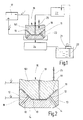
- valve body 11 for a fuel valve in particular for a fuel injection valve for internal combustion engines or internal combustion engines, is described below with reference to a device shown in Fig. 1 in the block diagram.
- a valve body 11 e.g. a multi-hole valve or a seat hole nozzle has several, lying in a wall surface 111 of the valve body 11, usually as injection holes designated outlet openings 12 for the fuel, which the inlets of the Form valve body 11 guided injection channels 13.
- Each outlet opening 12 is of a valve seat 14 formed on the wall surface 111 of the valve body 11 is formed is.
- Valve closure member 15 immersed in the valve body 11 a Valve closure member 15 which, with the valve seats 14 for closing and releasing the Outlet openings 12 and injection channels 13 cooperates, wherein the valve closing member 15th with line contact or very narrow surface contact on the valve seats 14 the Outlets 12 seals against the fuel inlet.
- the aim of the process is, on the one hand, a valve seat with polished surface quality
- a valve seat with polished surface quality On the other hand, in the valve body 11 to avoid dead volume, from which even at closed valve fuel through the spray channels 13 can flow.
- valve body 11 first of all the valve body 11 with injection channels 13 and roughly contoured wall surface 111 with the roughly contoured shape Valve seats 14 prefabricated.
- the desired final contour of the wall surface 111 and the Outlet openings 12 of the injection channels 13 enclosing valve seats 14 is on the Head surface of the tool head 161 of a tool 16 highly accurately simulated.
- the Tool 16 is lowered with its tool head 161 in the valve body 11, and Tool head 161 and valve body 11 are used as electrodes in an electrochemical Material removal process, in the course of which the contour of the surface of the Tool head 161 is accurately imaged on the wall surface 111 of the valve body 11.
- the electrochemical material removal process is known and is referred to as ECM process (Pulse unipolar electrochemical machining) for the production of holes with small Diameter already used.
- ECM process Pulse unipolar electrochemical machining
- the electrochemical Material removal process of the tool head 161 as a cathode and the valve body 10 as Anode operated in electrical pulse mode including the tool head 161 to the negative pole and the valve body 10 is connected to the positive pole of a pulse generator 17.
- Over a central bore 18 in the tool head 161 is a between the valve body 10 and the Surface of the tool head 161 forming working gap 19 is supplied to an electrolyte.
- the electrolyte is removed from a storage container 20 by means of a pump 21 and a Stabilization chamber 22 supplied to the electrolyte flow, at the central bore 18 in the Tool head 161 is connected.
- the working gap 19 supplied electrolyte flows over the spray channels 13 and the edges of the working gap 19 and is in a collecting container 23 caught. From there, the electrolyte enters a regenerator 24, in which also the vom Valve body 10 removed material is filtered out, and finally the again Reservoir 20 is supplied.
- a regenerator 24 in which also the vom Valve body 10 removed material is filtered out, and finally the again Reservoir 20 is supplied.
- the Tool head 161 a mechanical vibration movement in the axial direction, which by the Double arrow 25 is indicated in Fig. 1.
- valve body 10 with the during the electrochemical process in the Valve body 11 recessed tool head 161 shown enlarged in longitudinal section.
- the Wall surface 111 of the valve body 11 is already very far removed and has the contour of the Surface of the tool head 161 assumed.
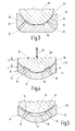
- Fig. 3 is the manufactured according to FIG Valve body 11 in conjunction with a cooperating with the valve seats 14 Valve closure member 15 shown in longitudinal section.
- valve seat 14 on the Wall surface 111 of the valve body 11 which corresponds with the help of a so to speak as a negative replicated contour on the surface of the tool head 161 produced as described is, can be seen in the sectional view of FIG. 4.
- the two each have a valve opening 13th enclosing valve seats 14 are opposite to the wall surface 111 of the valve body eleventh designed to be sublime, thus projecting beyond the wall surface 111.
- valve body 11 produced according to FIG. 4 is inserted therein, with the Valve seats 14 cooperating valve closure member 15 shown. It can be clearly seen that in this valve seat shape, the outlet openings 12 to the spray channels 13 at closed valve also completely opposite the remaining dead volume 10th are sealed below the valve closing member 15, so that the existing there fuel can not get into the outlet openings 12. The outflow of fuel over the Spray channels 13 in the combustion chamber of the engine is reliably prevented.
Landscapes
- Engineering & Computer Science (AREA)
- Mechanical Engineering (AREA)
- Chemical & Material Sciences (AREA)
- Combustion & Propulsion (AREA)
- General Engineering & Computer Science (AREA)
- Physics & Mathematics (AREA)
- Thermal Sciences (AREA)
- Manufacturing & Machinery (AREA)
- Fuel-Injection Apparatus (AREA)
Applications Claiming Priority (2)
| Application Number | Priority Date | Filing Date | Title |
|---|---|---|---|
| DE200410030762 DE102004030762A1 (de) | 2004-06-25 | 2004-06-25 | Verfahren zur Herstellung eines Ventilkörpers für ein Kraftstoffventil |
| DE102004030762 | 2004-06-25 |
Publications (2)
| Publication Number | Publication Date |
|---|---|
| EP1609552A1 true EP1609552A1 (fr) | 2005-12-28 |
| EP1609552B1 EP1609552B1 (fr) | 2010-02-17 |
Family
ID=35058221
Family Applications (1)
| Application Number | Title | Priority Date | Filing Date |
|---|---|---|---|
| EP20050102233 Expired - Lifetime EP1609552B1 (fr) | 2004-06-25 | 2005-03-21 | Méthode de fabrication d'un corps d'injecteur. |
Country Status (2)
| Country | Link |
|---|---|
| EP (1) | EP1609552B1 (fr) |
| DE (2) | DE102004030762A1 (fr) |
Families Citing this family (2)
| Publication number | Priority date | Publication date | Assignee | Title |
|---|---|---|---|---|
| DE102006060793A1 (de) * | 2006-12-21 | 2008-06-26 | Daimler Ag | Verfahren zur Bearbeitung eines Ventilsitzes |
| DE102009057410A1 (de) * | 2009-12-08 | 2011-06-09 | Continental Automotive Gmbh | Verfahren und Vorrichtung zum Bearbeiten eines Werkstücks |
Citations (4)
| Publication number | Priority date | Publication date | Assignee | Title |
|---|---|---|---|---|
| US4639568A (en) * | 1984-07-13 | 1987-01-27 | Ex-Cell-O Corporation | Apparatus and method for finishing fuel injector spray tips using EDM |
| EP0425236A1 (fr) * | 1989-10-26 | 1991-05-02 | Lucas Industries Public Limited Company | Buse d'injection de combustible pour moteurs à combustion interne |
| US5833835A (en) * | 1995-07-18 | 1998-11-10 | U.S. Philips Corporation | Method and apparatus for electrochemical machining by bipolar current pulses |
| DE10042612A1 (de) * | 1999-08-30 | 2001-04-26 | Riken Wako | Verfahren und Vorrichtung zum Schleifen einer inneren Oberfläche und Kraftstoffeinspritzdüse |
-
2004
- 2004-06-25 DE DE200410030762 patent/DE102004030762A1/de not_active Withdrawn
-
2005
- 2005-03-21 EP EP20050102233 patent/EP1609552B1/fr not_active Expired - Lifetime
- 2005-03-21 DE DE200550009019 patent/DE502005009019D1/de not_active Expired - Lifetime
Patent Citations (4)
| Publication number | Priority date | Publication date | Assignee | Title |
|---|---|---|---|---|
| US4639568A (en) * | 1984-07-13 | 1987-01-27 | Ex-Cell-O Corporation | Apparatus and method for finishing fuel injector spray tips using EDM |
| EP0425236A1 (fr) * | 1989-10-26 | 1991-05-02 | Lucas Industries Public Limited Company | Buse d'injection de combustible pour moteurs à combustion interne |
| US5833835A (en) * | 1995-07-18 | 1998-11-10 | U.S. Philips Corporation | Method and apparatus for electrochemical machining by bipolar current pulses |
| DE10042612A1 (de) * | 1999-08-30 | 2001-04-26 | Riken Wako | Verfahren und Vorrichtung zum Schleifen einer inneren Oberfläche und Kraftstoffeinspritzdüse |
Also Published As
| Publication number | Publication date |
|---|---|
| EP1609552B1 (fr) | 2010-02-17 |
| DE102004030762A1 (de) | 2006-01-19 |
| DE502005009019D1 (de) | 2010-04-01 |
Similar Documents
| Publication | Publication Date | Title |
|---|---|---|
| EP3138647B1 (fr) | Dispositif et procédé destinés à l'usinage électrochimique de pièces à usiner | |
| DE10360080A1 (de) | Verfahren und Vorrichtung zum Abtragen von metallischem Material eines Werkstücks | |
| DE112016004270T5 (de) | Elektrisches Funkenerosions-Verfahren zur Erzeugung von variablen Spritzloch-Geometrien | |
| DE112004000897T5 (de) | Kraftstoffeinspritzventil mit einer Düsenscheibe und Verfahren zum Herstellen der Düsenscheibe mit einem asymmetrischen Dorn | |
| DE10046304C1 (de) | Verfahren zum Herstellen eines Ventilsitzkörpers eines Brennstoffeinspritzventils | |
| DE2701291A1 (de) | Verfahren zur herstellung des koerperendes einer elektromagnetischen einspritzduese sowie elektromagnetische einspritzduese | |
| EP1609552B1 (fr) | Méthode de fabrication d'un corps d'injecteur. | |
| EP1644635A1 (fr) | Soupape d'injection de carburant et son procede de fabrication | |
| DE102016004584B4 (de) | Verfahren zur Bearbeitung eines Einspritzventils zum Einspritzen von Kraftstoff in einen Verbrennungsmotor | |
| EP2943681B1 (fr) | Moyen de dosage et d'injection de carburant, et procédé de fabrication d'un moyen de dosage et d'injection de carburant | |
| DE102011002658A1 (de) | Verfahren zum Herstellen von Bohrungen | |
| DE2358220A1 (de) | Verfahren zur herstellung eines kraftstoffeinlagerungsraumes fuer kraftstoffeinspritzventile | |
| DE102005009831B4 (de) | Verfahren zur Herstellung einer Ventilanordnung, insbesondere für ein Expansionsventil sowie eine Ventilanordnung | |
| DE102018005849A1 (de) | Gemischbildungsraumabgrenzungsteil und Verfahren zu dessen Herstellung | |
| DE19963389A1 (de) | Verfahren zur Herstellung eines Ventilstücks für eine Kraftstoff-Einspritzvorrichtung | |
| DE102004032201B3 (de) | Verfahren zur Bearbeitung von hochdruckfesten Dichtflächen an zwei metallischen Körpern | |
| DE102013225018B4 (de) | Verfahren zum Herstellen eines Düsenkörpers | |
| DE2725707A1 (de) | Einspritzduese fuer brennkraftmaschinen | |
| DE202016002391U1 (de) | Einspritzventil zum Einspritzen von Kraftstoff in einen Verbrennungsmotor | |
| DE112019001528T5 (de) | Kraftstoffeinspritzventilsitzanordnung, die einen einsatz umfasst, der einen ventilsitz bildet | |
| DE112019001538T5 (de) | Kraftstoffeinspritzventilsitzanordnung, die einen in position geformten einsatz umfasst, und verfahren zur herstellung davonhintergrund | |
| DE112019001387T5 (de) | Kraftstoffeinspritzventilsitzanordnung, die einsatzpositionierungs- und -haltemerkmale umfasst | |
| DE102019213342A1 (de) | Verfahren und Vorrichtung zum elektrochemischen Bearbeiten von Bauteilen | |
| DE102016203229A1 (de) | Elektrodenanordnung und Verfahren zur elektrochemischen Bearbeitung eines metallischen Bauteils, insbesondere eines Kraftstoffinjektorgehäuses | |
| DE112019001530T5 (de) | Kraftstoffeinspritzventilsitzanordnung, die einsatzabdichtungsmerkmale umfasst |
Legal Events
| Date | Code | Title | Description |
|---|---|---|---|
| PUAI | Public reference made under article 153(3) epc to a published international application that has entered the european phase |
Free format text: ORIGINAL CODE: 0009012 |
|
| AK | Designated contracting states |
Kind code of ref document: A1 Designated state(s): AT BE BG CH CY CZ DE DK EE ES FI FR GB GR HU IE IS IT LI LT LU MC NL PL PT RO SE SI SK TR |
|
| AX | Request for extension of the european patent |
Extension state: AL BA HR LV MK YU |
|
| 17P | Request for examination filed |
Effective date: 20060628 |
|
| AKX | Designation fees paid |
Designated state(s): DE FR IT |
|
| 17Q | First examination report despatched |
Effective date: 20060921 |
|
| GRAP | Despatch of communication of intention to grant a patent |
Free format text: ORIGINAL CODE: EPIDOSNIGR1 |
|
| GRAS | Grant fee paid |
Free format text: ORIGINAL CODE: EPIDOSNIGR3 |
|
| GRAA | (expected) grant |
Free format text: ORIGINAL CODE: 0009210 |
|
| AK | Designated contracting states |
Kind code of ref document: B1 Designated state(s): DE FR IT |
|
| REF | Corresponds to: |
Ref document number: 502005009019 Country of ref document: DE Date of ref document: 20100401 Kind code of ref document: P |
|
| PLBE | No opposition filed within time limit |
Free format text: ORIGINAL CODE: 0009261 |
|
| STAA | Information on the status of an ep patent application or granted ep patent |
Free format text: STATUS: NO OPPOSITION FILED WITHIN TIME LIMIT |
|
| 26N | No opposition filed |
Effective date: 20101118 |
|
| PGFP | Annual fee paid to national office [announced via postgrant information from national office to epo] |
Ref country code: FR Payment date: 20110401 Year of fee payment: 7 |
|
| PGFP | Annual fee paid to national office [announced via postgrant information from national office to epo] |
Ref country code: IT Payment date: 20110329 Year of fee payment: 7 |
|
| REG | Reference to a national code |
Ref country code: FR Ref legal event code: ST Effective date: 20121130 |
|
| PG25 | Lapsed in a contracting state [announced via postgrant information from national office to epo] |
Ref country code: FR Free format text: LAPSE BECAUSE OF NON-PAYMENT OF DUE FEES Effective date: 20120402 |
|
| PG25 | Lapsed in a contracting state [announced via postgrant information from national office to epo] |
Ref country code: IT Free format text: LAPSE BECAUSE OF NON-PAYMENT OF DUE FEES Effective date: 20120321 |
|
| PGFP | Annual fee paid to national office [announced via postgrant information from national office to epo] |
Ref country code: DE Payment date: 20190520 Year of fee payment: 15 |
|
| REG | Reference to a national code |
Ref country code: DE Ref legal event code: R119 Ref document number: 502005009019 Country of ref document: DE |
|
| PG25 | Lapsed in a contracting state [announced via postgrant information from national office to epo] |
Ref country code: DE Free format text: LAPSE BECAUSE OF NON-PAYMENT OF DUE FEES Effective date: 20201001 |