EP1609628A1 - Systeme de capteur pour pneu - Google Patents
Systeme de capteur pour pneu Download PDFInfo
- Publication number
- EP1609628A1 EP1609628A1 EP04723079A EP04723079A EP1609628A1 EP 1609628 A1 EP1609628 A1 EP 1609628A1 EP 04723079 A EP04723079 A EP 04723079A EP 04723079 A EP04723079 A EP 04723079A EP 1609628 A1 EP1609628 A1 EP 1609628A1
- Authority
- EP
- European Patent Office
- Prior art keywords
- sensor unit
- tire
- sensor
- installation position
- air chamber
- Prior art date
- Legal status (The legal status is an assumption and is not a legal conclusion. Google has not performed a legal analysis and makes no representation as to the accuracy of the status listed.)
- Withdrawn
Links
Images

Classifications
-
- B—PERFORMING OPERATIONS; TRANSPORTING
- B60—VEHICLES IN GENERAL
- B60C—VEHICLE TYRES; TYRE INFLATION; TYRE CHANGING; CONNECTING VALVES TO INFLATABLE ELASTIC BODIES IN GENERAL; DEVICES OR ARRANGEMENTS RELATED TO TYRES
- B60C23/00—Devices for measuring, signalling, controlling, or distributing tyre pressure or temperature, specially adapted for mounting on vehicles; Arrangement of tyre inflating devices on vehicles, e.g. of pumps or of tanks; Tyre cooling arrangements
- B60C23/02—Signalling devices actuated by tyre pressure
- B60C23/04—Signalling devices actuated by tyre pressure mounted on the wheel or tyre
- B60C23/0408—Signalling devices actuated by tyre pressure mounted on the wheel or tyre transmitting the signals by non-mechanical means from the wheel or tyre to a vehicle body mounted receiver
Definitions
- the present invention relates to a sensor system for a tire, which detects information inside the tire such as an air pressure and a temperature, and more particularly relates to a sensor system for a tire which enables an installation condition of a sensor unit in a tire's air chamber to be known.
- a sensor unit is installed in a tire's air chamber.
- the falling of the sensor unit cannot be known. If a vehicle runs while the sensor unit has fallen off, an electronic component of the sensor unit will be destroyed, and communication may be disabled or a false alarm may be given.
- a sensor system for a tire of the present invention to achieve the foregoing object is a sensor system for a tire, in which a sensor unit is installed in a tire's air chamber, including detecting means for detecting a relative change in a distance between the sensor unit and a position where the sensor unit should be installed.
- the detecting means for detecting the relative change in the distance between the sensor unit and the position where the sensor unit should be installed if the sensor unit falls off a predetermined installation position in assembly of a rim, the falling of the sensor unit can be easily known. Therefore, destruction of an electronic component, disabled communication, a false alarm, and the like attributable to the falling of the sensor unit can be prevented.
- the following structure in order to detect the relative change in the distance between the sensor unit and its installation position, the following structure can be adopted.
- a sensor system for a tire of the present invention is a sensor system for a tire, in which a sensor unit is installed in a tire's air chamber, including: a base which fixes the sensor unit in its installation position, the base being attached to the sensor unit; a conductive path with a pair of contact points formed in the base, the conductive path connecting the contact points thereof; and a detection circuit with a pair of contact points formed in the sensor unit, the detection circuit connecting the contact points thereof, and the contact points being arranged corresponding to positions of the contact points in the base.
- a relative change in a distance between the sensor unit and its installation position is detected based on an open and closed state of the detection circuit.
- a sensor system for a tire of the present invention is a sensor system for a tire, in which a sensor unit is installed in a tire's air chamber, including a proximity sensor which reacts to metal, the proximity sensor being arranged in the sensor unit.
- a relative change in a distance between the sensor unit and its installation position is detected based on an output of the proximity sensor.
- a sensor system for a tire of the present invention is a sensor system for a tire, in which a sensor unit is installed in a tire's air chamber, including, a probing member which is elastically energized toward an installation position of the sensor unit, the probing member being arranged in the sensor unit.
- a relative change in a distance between the sensor unit and its installation position is detected based on displacement of the probing member.
- a sensor system for a tire of the present invention is a sensor system for a tire, in which a sensor unit is installed in a tire's air chamber, including a passive transponder mounted in the sensor unit.
- a relative change in a distance between the sensor unit and its installation position is detected based on a response of the passive transponder to a reader having a limited output.
- the sensor unit includes an electronic component required to detect information inside the tire, the component being housed in a case.
- the electronic component which constitutes the sensor unit, and structure of the case, are not particularly limited.
- Fig. 1 shows a sensor system for a tire according to a first embodiment of the present invention.
- R denotes a rim
- T denotes a tire
- S denotes a tire's air chamber.
- the sensor system for a tire of this embodiment includes a sensor unit 1 for detecting information inside the tire, and a base 11 for fixing the sensor unit 1.
- the sensor unit 1 is installed in the tire's air chamber by means of the base 11.
- the sensor unit 1 includes an electronic component in a case, measures an air pressure of the tire and an internal temperature thereof, and transmits the measurement results to the outside of the tire.
- the base 11 includes at least a pair of locking parts 13 and 13 which are protruded from a bottom part 12. These locking parts 13 and 13 lock the sensor unit 1 by sandwiching the unit.
- the bottom part 12 of the base 11 is fixed to an outer peripheral surface of the rim R, for example.
- the sensor unit 1 is attachable to and detachable from the base 11 fixed to the outer peripheral surface of the rim R.
- a pair of contact points 14 and 14 are provided at portions of the base 11 where the base comes into contact with the sensor unit 1. Moreover, in the base 11, a conductive path 15 is formed, which electrically connects the pair of contact points 14 and 14 to each other. Meanwhile, a pair of contact points 2 and 2 are provided at portions of the sensor unit 1 where the unit comes into contact with the base 11. Moreover, in the sensor unit 1, a detection circuit 3 is formed, which electrically connects the pair of contact points 2 and 2 to each other. This detection circuit 3 is formed in the electronic component of the sensor unit 1.
- the detection circuit 3 when the sensor unit 1 is attached to the base 11, the detection circuit 3 is set in a closed state. On the other hand, if the sensor unit 1 becomes detached from the base 11 or moves out from a predetermined locking position on the base 11 in assembly of the rim and the like, the detection circuit 3 is set in an open state. Therefore, based on the open or closed state of the detection circuit 3, a relative change in a distance between the sensor unit 1 and a position where the sensor unit should be installed is detected. Thus, an installation condition of the sensor unit 1 can be known.
- Fig. 2 shows a sensor system for a tire according to a second embodiment of the present invention.
- R denotes a rim
- T denotes a tire
- S denotes a tire's air chamber.
- the sensor system for a tire of this embodiment includes a sensor unit 21 for detecting information inside the tire.
- the sensor unit 21 is installed in the tire's air chamber.
- the sensor unit 21 includes an electronic component in a case, measures an air pressure of the tire and an internal temperature thereof, and transmits the measurement results to the outside of the tire.
- an eddy-current type proximity sensor 22 which reacts to metal is provided in the sensor unit 21.
- This proximity sensor 22 is disposed so as to face a position where the sensor unit 21 is installed, and generates an output according to a mass of and a distance from a metal member existing in the position.
- the proximity sensor 22 can be configured as described below. Sensitivity of the proximity sensor 22 is controlled so as to react to the rim R made of metal, and, when the proximity sensor 22 comes off the rim R, the sensor no longer reacts to the rim.
- the proximity sensor 22 can be also configured as described below.
- the sensitivity of the proximity sensor 22 is controlled so as to react to a steel wire embedded inside the tire, and, when the proximity sensor 22 comes off the tire, the sensor no longer reacts to the steel wire.
- the proximity sensor 22 is used as a switch.
- an output of the proximity sensor 22 when the sensor unit 21 is installed in a normal position is stored, and a relative change in a distance between the sensor unit 21 and its installation position may be detected based on a change in the output.
- the proximity sensor 22 when the sensor unit 21 is installed in a predetermined position, the proximity sensor 22 generates a predetermined output. Meanwhile, if the sensor unit 21 becomes detached from its installation position in assembly of the rim and the like, the output of the proximity sensor 22 changes. Therefore, the relative change in the distance between the sensor unit 21 and its installation position is detected based on the output of the proximity sensor 22. Thus, an installation condition of the sensor unit 21 can be known.
- Fig. 3 shows a sensor system for a tire according to a third embodiment of the present invention.
- R denotes a rim
- T denotes a tire
- S denotes a tire's air chamber.
- the sensor system for a tire of this embodiment includes a sensor unit 31 for detecting information inside the tire.
- the sensor unit 31 is installed in the tire's air chamber.
- the sensor unit 31 includes an electronic component in a case, measures an air pressure of the tire and an internal temperature thereof, and transmits the measurement results to the outside of the tire.
- a rod-like probing member 32 which is elastically energized toward an installation position of the sensor unit 31 is provided in the sensor unit 31.
- the probing member 32 can freely come out of or get back into the sensor unit 31 while being energized by an elastic body 33 such as a spring.
- the sensor unit 31 is installed in a state where the probing member 32 pressed against the installation position is housed in the sensor unit 31.
- a circuit which is opened or closed according to a position of the probing member 32 is provided.
- the probing member 32 is set in a state of being housed in the sensor unit 31. Meanwhile, if the sensor unit 31 becomes detached from its installation position in assembly of the rim and the like, the probing member 32 comes out of the sensor unit 31, and a relative position of the probing member 32 in the sensor unit 31 is changed. Therefore, a relative change in a distance between the sensor unit 31 and its installation position is detected based on displacement of the probing member 32. Thus, an installation condition of the sensor unit 31 can be known.
- the installation condition of the sensor unit may be constantly monitored. In such a case, however, too much power is consumed.
- detecting means for detecting the relative change in the distance between the sensor unit and its installation position be operated at predetermined time intervals.
- a detection result concerning the installation condition of the sensor unit may be transmitted to the outside of the tire by utilizing a transmitter that is included in the electronic component of the sensor unit.
- a code for the predetermined position in a communication protocol may be changed or a protocol signal different from a usual one may be transmitted.
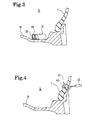
- Fig. 4 shows a sensor system for a tire according to a fourth embodiment of the present invention.
- R denotes a rim
- T denotes a tire
- S denotes a tire's air chamber.
- the sensor system for a tire of this embodiment includes a sensor unit 41 for detecting information inside the tire.
- the sensor unit 41 is installed in the tire's air chamber.
- the sensor unit 41 includes an electronic component in a case, measures an air pressure of the tire and an internal temperature thereof, and transmits the measurement results to the outside of the tire.
- the sensor unit 41 includes a passive transponder 42.
- This passive transponder 42 transmits a response signal in response to an inquiry signal from the outside of the tire.
- the passive transponder 42 may be inserted into the case of the sensor unit 41 as an independent component or may be included in a circuit of the electronic component of the sensor unit 41.
- a reader (scanner) 43 for providing the inquiry signal is simultaneously used.
- This reader 43 has a limited output. Specifically, an output range of the reader 43 is limited within a 10-cm radius, preferably within a 5-cm radius. Accordingly, if the passive transponder 42 is out of the output range of the reader 43, the response signal cannot be obtained for the inquiry signal.
- the sensor unit 41 is installed in a predetermined position on an inner surface of the tire T.
- the sensor unit 41 is installed behind a specific character displayed on a side face of the tire on an outer side of a vehicle. Accordingly, in a state where the rim is assembled, the reader 43 is brought close to a position where the sensor unit 41 should be installed from the outside of the tire. Thus, the inquiry signal is provided. In this event, the response signal can be obtained if the sensor unit 41 is installed in the predetermined position. The response signal cannot be obtained, however, if the sensor unit 41 does not exist in the predetermined position. Therefore, a relative change in a distance between the sensor unit 41 and its installation position is detected based on a response of the passive transponder 42 to the reader 43 having the limited output. Thus, an installation condition of the sensor unit 41 can be known.
- the present invention can be effectively utilized in tire manufacturing industries and thus in automobile manufacturing industries.
Landscapes
- Engineering & Computer Science (AREA)
- Mechanical Engineering (AREA)
- Measuring Fluid Pressure (AREA)
Applications Claiming Priority (3)
| Application Number | Priority Date | Filing Date | Title |
|---|---|---|---|
| JP2003094884A JP4169623B2 (ja) | 2003-03-31 | 2003-03-31 | タイヤ用センサシステム |
| JP2003094884 | 2003-03-31 | ||
| PCT/JP2004/004124 WO2004087440A1 (fr) | 2003-03-31 | 2004-03-24 | Systeme de capteur pour pneu |
Publications (2)
| Publication Number | Publication Date |
|---|---|
| EP1609628A1 true EP1609628A1 (fr) | 2005-12-28 |
| EP1609628A4 EP1609628A4 (fr) | 2006-04-12 |
Family
ID=33127414
Family Applications (1)
| Application Number | Title | Priority Date | Filing Date |
|---|---|---|---|
| EP04723079A Withdrawn EP1609628A4 (fr) | 2003-03-31 | 2004-03-24 | Systeme de capteur pour pneu |
Country Status (6)
| Country | Link |
|---|---|
| US (1) | US7370522B2 (fr) |
| EP (1) | EP1609628A4 (fr) |
| JP (1) | JP4169623B2 (fr) |
| CN (1) | CN100439133C (fr) |
| CA (1) | CA2515910A1 (fr) |
| WO (1) | WO2004087440A1 (fr) |
Cited By (2)
| Publication number | Priority date | Publication date | Assignee | Title |
|---|---|---|---|---|
| DE102007046485A1 (de) * | 2007-09-28 | 2009-04-23 | Continental Automotive Gmbh | Vorrichtung zur Zustandsüberwachung eines elektrisch leitenden Felgenbands, Radeinheit mit einer solchen Vorrichtung sowie Verfahren zur Zustandsüberwachung eines Felgenbands |
| WO2014041060A1 (fr) * | 2012-09-17 | 2014-03-20 | Bayerische Motoren Werke Aktiengesellschaft | Stockage d'informations concernant un pneu dans un capteur de pneu |
Families Citing this family (8)
| Publication number | Priority date | Publication date | Assignee | Title |
|---|---|---|---|---|
| FR2874271B1 (fr) * | 2004-08-10 | 2006-11-24 | Siemens Vdo Automotive Sas | Procede et dispositif de detection de la desolidarisation d'un capteur par rapport a un vehicule sur lequel est monte le dit capteur |
| DE102005006904B4 (de) * | 2004-11-18 | 2014-10-30 | Volkswagen Ag | Reifendruckkontrollsystem für ein Fahrzeug |
| US7271709B2 (en) * | 2005-08-18 | 2007-09-18 | Ford Global Technologies, Llc | Robust method and system for the automatic detection of a detached remote tire pressure sensor of a tire pressure monitoring system |
| US20070088479A1 (en) * | 2005-10-19 | 2007-04-19 | Trw Automotive U.S. Llc | Apparatus with sensor assembly for sensing a vehicle crash condition and associated method |
| EP2473676B8 (fr) * | 2009-08-31 | 2018-11-21 | Compagnie Générale des Etablissements Michelin | Procédé et appareil pour déterminer la profondeur d' un élément métallique dans un matériau en caoutchouc ou élastomère |
| DE102011003134A1 (de) | 2011-01-25 | 2012-07-26 | Bayerische Motoren Werke Aktiengesellschaft | Anordnung einer Reifendruck-Sensoreinheit |
| JP6048291B2 (ja) * | 2013-04-17 | 2016-12-21 | 株式会社デンソー | センサ装置 |
| JP6567471B2 (ja) | 2016-06-30 | 2019-08-28 | 株式会社ブリヂストン | 加速度センサの脱落判定方法及び加速度センサの脱落判定装置 |
Family Cites Families (17)
| Publication number | Priority date | Publication date | Assignee | Title |
|---|---|---|---|---|
| US4578992A (en) * | 1982-11-05 | 1986-04-01 | Philip E. Galasko | Detection of a low pressure condition of a vehicle tire |
| GB8430389D0 (en) * | 1984-12-01 | 1985-01-09 | Bamford Excavators Ltd | Earth moving machine |
| US5181975A (en) * | 1991-03-27 | 1993-01-26 | The Goodyear Tire & Rubber Company | Integrated circuit transponder with coil antenna in a pneumatic tire for use in tire identification |
| JP2715741B2 (ja) * | 1991-10-02 | 1998-02-18 | ダイキン工業株式会社 | 空気調和装置 |
| JP2536354B2 (ja) * | 1991-10-11 | 1996-09-18 | ダイキン工業株式会社 | 冷凍装置の保護装置 |
| US5287626A (en) * | 1992-11-16 | 1994-02-22 | Reich Dennis A | Apparatus and method for measuring rotation angle |
| JPH10504783A (ja) | 1994-08-31 | 1998-05-12 | オター コントロールズ リミテッド | タイヤ状態監視システム |
| US5620286A (en) * | 1994-11-09 | 1997-04-15 | Rank Taylor Hobson, Ltd. | Flycutting machine for manufacturing printed circuit boards |
| EP0954773B1 (fr) * | 1997-01-22 | 2002-09-04 | Siemens Aktiengesellschaft | Procede et dispositif pour la mise a poste d'une unite mobile autonome |
| JP3161349B2 (ja) * | 1997-02-05 | 2001-04-25 | 株式会社豊田自動織機製作所 | 産業車両の車体揺動制御装置 |
| JP3869909B2 (ja) | 1997-05-20 | 2007-01-17 | 横浜ゴム株式会社 | 空気入りタイヤの内圧検知装置 |
| US6448977B1 (en) * | 1997-11-14 | 2002-09-10 | Immersion Corporation | Textures and other spatial sensations for a relative haptic interface device |
| US6269688B1 (en) * | 1997-12-04 | 2001-08-07 | Intercomp Company | Apparatus and method for testing tires |
| GB2370640A (en) * | 2000-08-08 | 2002-07-03 | Transense Technologies Plc | SAW device with integral patch antenna |
| US6420967B1 (en) * | 2001-01-31 | 2002-07-16 | Lear Corporation | System and method for shared vehicle tire pressure monitoring, remote keyless entry, and vehicle immobilization |
| DE10137591B4 (de) * | 2001-08-01 | 2005-07-14 | Daimlerchrysler Ag | Telemetrisches Reifendruck-Kontrollsystem |
| US6931920B2 (en) * | 2003-07-16 | 2005-08-23 | Lear Corporation | Tire monitoring system |
-
2003
- 2003-03-31 JP JP2003094884A patent/JP4169623B2/ja not_active Expired - Fee Related
-
2004
- 2004-03-24 WO PCT/JP2004/004124 patent/WO2004087440A1/fr not_active Ceased
- 2004-03-24 CN CNB2004800076414A patent/CN100439133C/zh not_active Expired - Fee Related
- 2004-03-24 US US10/546,811 patent/US7370522B2/en not_active Expired - Fee Related
- 2004-03-24 CA CA002515910A patent/CA2515910A1/fr not_active Abandoned
- 2004-03-24 EP EP04723079A patent/EP1609628A4/fr not_active Withdrawn
Cited By (3)
| Publication number | Priority date | Publication date | Assignee | Title |
|---|---|---|---|---|
| DE102007046485A1 (de) * | 2007-09-28 | 2009-04-23 | Continental Automotive Gmbh | Vorrichtung zur Zustandsüberwachung eines elektrisch leitenden Felgenbands, Radeinheit mit einer solchen Vorrichtung sowie Verfahren zur Zustandsüberwachung eines Felgenbands |
| WO2014041060A1 (fr) * | 2012-09-17 | 2014-03-20 | Bayerische Motoren Werke Aktiengesellschaft | Stockage d'informations concernant un pneu dans un capteur de pneu |
| US9764605B2 (en) | 2012-09-17 | 2017-09-19 | Bayerische Motoren Werke Aktiengesellschaft | Storing of tire information in a tire sensor |
Also Published As
| Publication number | Publication date |
|---|---|
| WO2004087440A1 (fr) | 2004-10-14 |
| CN100439133C (zh) | 2008-12-03 |
| JP4169623B2 (ja) | 2008-10-22 |
| US7370522B2 (en) | 2008-05-13 |
| EP1609628A4 (fr) | 2006-04-12 |
| JP2004299536A (ja) | 2004-10-28 |
| CA2515910A1 (fr) | 2004-10-14 |
| CN1761583A (zh) | 2006-04-19 |
| US20060196257A1 (en) | 2006-09-07 |
Similar Documents
| Publication | Publication Date | Title |
|---|---|---|
| JP7092486B2 (ja) | ホイールファスナアラーム | |
| JP3381194B2 (ja) | 車両のタイヤパラメータデータを検知し送出するトランスポンダ及びセンサー装置 | |
| US7370522B2 (en) | Sensor system for tire | |
| US6087930A (en) | Active integrated circuit transponder and sensor apparatus for transmitting vehicle tire parameter data | |
| KR101109205B1 (ko) | 봉인부 | |
| US8310356B2 (en) | Wireless brake electronic wear sensors | |
| KR100462122B1 (ko) | 타이어 상태 감시장치 | |
| EP0662050B1 (fr) | Systeme de controle de l'etat des pneus | |
| US20070262853A1 (en) | Vehicle alarm | |
| WO2012042515A4 (fr) | Module de détection d'état et de communication et système de traçage à distance de cadenas | |
| EP1398736B1 (fr) | Appareil et procédé pour surveiller la pression des pneumatiques | |
| GB9925021D0 (en) | Wireless health monitoring system | |
| CN1476389A (zh) | 低电流消耗的轮胎压力监测系统 | |
| US6693520B2 (en) | Safety back-up sensor for a vehicle | |
| KR20010039558A (ko) | 타이어 공기압 감시장치 및 그 방법 | |
| JP3936612B2 (ja) | マグネットセンサ、マグネットセンサシステム、警報システム及びホームセキュリティシステム | |
| CN111163976A (zh) | 安全带锁系统 | |
| AU2019332047B2 (en) | Fastener | |
| EP1682388B1 (fr) | Detecteur d'occupation de siege | |
| US6093978A (en) | Security system for a motor vehicle opening leaf comprising improved connection means | |
| EP1085990A1 (fr) | Capteur de pression pour pneu et systeme d'alarme correspondant | |
| US20030112136A1 (en) | Tire pressure warning device | |
| JPS63293318A (ja) | ボ−ルジョイントの摩耗検出装置 | |
| WO2007130670A2 (fr) | Alarme pour véhicule | |
| JP2005331361A (ja) | タイヤ空気圧警報センサ |
Legal Events
| Date | Code | Title | Description |
|---|---|---|---|
| PUAI | Public reference made under article 153(3) epc to a published international application that has entered the european phase |
Free format text: ORIGINAL CODE: 0009012 |
|
| 17P | Request for examination filed |
Effective date: 20050909 |
|
| AK | Designated contracting states |
Kind code of ref document: A1 Designated state(s): AT BE BG CH CY CZ DE DK EE ES FI FR GB GR HU IE IT LI LU MC NL PL PT RO SE SI SK TR |
|
| AX | Request for extension of the european patent |
Extension state: AL LT LV MK |
|
| A4 | Supplementary search report drawn up and despatched |
Effective date: 20060228 |
|
| DAX | Request for extension of the european patent (deleted) | ||
| RBV | Designated contracting states (corrected) |
Designated state(s): DE FR GB |
|
| 17Q | First examination report despatched |
Effective date: 20061128 |
|
| STAA | Information on the status of an ep patent application or granted ep patent |
Free format text: STATUS: THE APPLICATION IS DEEMED TO BE WITHDRAWN |
|
| 18D | Application deemed to be withdrawn |
Effective date: 20090311 |