EP1609663A1 - Vorrichtung und Verfahren zum Überprüfen und/oder Kalibrieren einer in einem Fahrzeugsitz angeordneten Insassenerkennungseinrichtung - Google Patents
Vorrichtung und Verfahren zum Überprüfen und/oder Kalibrieren einer in einem Fahrzeugsitz angeordneten Insassenerkennungseinrichtung Download PDFInfo
- Publication number
- EP1609663A1 EP1609663A1 EP04014871A EP04014871A EP1609663A1 EP 1609663 A1 EP1609663 A1 EP 1609663A1 EP 04014871 A EP04014871 A EP 04014871A EP 04014871 A EP04014871 A EP 04014871A EP 1609663 A1 EP1609663 A1 EP 1609663A1
- Authority
- EP
- European Patent Office
- Prior art keywords
- seat
- vehicle seat
- child
- child seat
- vehicle
- Prior art date
- Legal status (The legal status is an assumption and is not a legal conclusion. Google has not performed a legal analysis and makes no representation as to the accuracy of the status listed.)
- Granted
Links
Images


Classifications
-
- B—PERFORMING OPERATIONS; TRANSPORTING
- B60—VEHICLES IN GENERAL
- B60R—VEHICLES, VEHICLE FITTINGS, OR VEHICLE PARTS, NOT OTHERWISE PROVIDED FOR
- B60R21/00—Arrangements or fittings on vehicles for protecting or preventing injuries to occupants or pedestrians in case of accidents or other traffic risks
- B60R21/01—Electrical circuits for triggering passive safety arrangements, e.g. airbags, safety belt tighteners, in case of vehicle accidents or impending vehicle accidents
- B60R21/015—Electrical circuits for triggering passive safety arrangements, e.g. airbags, safety belt tighteners, in case of vehicle accidents or impending vehicle accidents including means for detecting the presence or position of passengers, passenger seats or child seats, and the related safety parameters therefor, e.g. speed or timing of airbag inflation in relation to occupant position or seat belt use
- B60R21/01556—Child-seat detection systems
-
- B—PERFORMING OPERATIONS; TRANSPORTING
- B60—VEHICLES IN GENERAL
- B60N—SEATS SPECIALLY ADAPTED FOR VEHICLES; VEHICLE PASSENGER ACCOMMODATION NOT OTHERWISE PROVIDED FOR
- B60N2/00—Seats specially adapted for vehicles; Arrangement or mounting of seats in vehicles
- B60N2/002—Seats provided with an occupancy detection means mounted therein or thereon
-
- B—PERFORMING OPERATIONS; TRANSPORTING
- B60—VEHICLES IN GENERAL
- B60N—SEATS SPECIALLY ADAPTED FOR VEHICLES; VEHICLE PASSENGER ACCOMMODATION NOT OTHERWISE PROVIDED FOR
- B60N2/00—Seats specially adapted for vehicles; Arrangement or mounting of seats in vehicles
- B60N2/24—Seats specially adapted for vehicles; Arrangement or mounting of seats in vehicles for particular purposes or particular vehicles
- B60N2/26—Seats specially adapted for vehicles; Arrangement or mounting of seats in vehicles for particular purposes or particular vehicles for children
- B60N2/28—Seats readily mountable on, and dismountable from, existing seats or other parts of the vehicle
-
- G—PHYSICS
- G01—MEASURING; TESTING
- G01M—TESTING STATIC OR DYNAMIC BALANCE OF MACHINES OR STRUCTURES; TESTING OF STRUCTURES OR APPARATUS, NOT OTHERWISE PROVIDED FOR
- G01M99/00—Subject matter not provided for in other groups of this subclass
- G01M99/001—Testing of furniture, e.g. seats or mattresses
-
- B—PERFORMING OPERATIONS; TRANSPORTING
- B60—VEHICLES IN GENERAL
- B60N—SEATS SPECIALLY ADAPTED FOR VEHICLES; VEHICLE PASSENGER ACCOMMODATION NOT OTHERWISE PROVIDED FOR
- B60N2/00—Seats specially adapted for vehicles; Arrangement or mounting of seats in vehicles
- B60N2/24—Seats specially adapted for vehicles; Arrangement or mounting of seats in vehicles for particular purposes or particular vehicles
- B60N2/26—Seats specially adapted for vehicles; Arrangement or mounting of seats in vehicles for particular purposes or particular vehicles for children
- B60N2/266—Seats specially adapted for vehicles; Arrangement or mounting of seats in vehicles for particular purposes or particular vehicles for children with detection or alerting means responsive to presence or absence of children; with detection or alerting means responsive to improper locking or installation of the child seats or parts thereof
- B60N2/268—Seats specially adapted for vehicles; Arrangement or mounting of seats in vehicles for particular purposes or particular vehicles for children with detection or alerting means responsive to presence or absence of children; with detection or alerting means responsive to improper locking or installation of the child seats or parts thereof detecting or alerting means responsive to the installation of the child seats in the vehicle
-
- B—PERFORMING OPERATIONS; TRANSPORTING
- B60—VEHICLES IN GENERAL
- B60N—SEATS SPECIALLY ADAPTED FOR VEHICLES; VEHICLE PASSENGER ACCOMMODATION NOT OTHERWISE PROVIDED FOR
- B60N2210/00—Sensor types, e.g. for passenger detection systems or for controlling seats
- B60N2210/40—Force or pressure sensors
Definitions
- the invention relates to a device and a method for checking and / or calibrating an occupant detection device arranged in a vehicle seat, in a child seat to a vehicle seat is pressed or in which a vehicle seat is acted upon by a child seat and a corresponding reaction of the occupant detection device of the vehicle seat is evaluated.
- the checking or calibrating a arranged in a vehicle seat Occupant recognition device is known in principle.
- goal of Verification is to find out if the occupant detection device an occupancy of the vehicle seat, in the present case by a in Child sitting in a child seat, recorded correctly. If this is not the case, then the occupant recognition device can be corrected accordingly.
- the problem is that the occupant detection device not only a Variety of structurally different child seats must recognize but that this detection also in different mounting positions a child seat, fastenings of the child seat and assignments of the child seat Child seat with different heavy children done reliably got to.
- This procedure can be carried out with other child seats and on several vehicle seats are repeated to remove all existing ones Child seats and vehicle seats to create a test matrix, based derer the function of the occupant detection device for in the Practice essentially occurring cases assessable or adjustable.
- the invention is based on the object, an apparatus and a method to create an accelerated and in particular to reliable and reproducible results leading review and / or calibration of an occupant detection device arranged in a vehicle seat allows.
- the device according to the invention comprises a child seat storage for storage at least one child seat, a vehicle seat mount for Recording at least one vehicle seat and a robot through which a child seat mounted in the child seat bearing can be removed from the child seat bearing and a vehicle seat held in the vehicle seat mount is pressable.
- each child seat for Simulation of possible installation positions and / or seat occupancy of the Child seat in different predetermined relative positions with respect each vehicle seat and / or different degrees to these pressed be.
- Installation options or assignments of the child seat by simulates the robot and during the check or calibration of the Occupant recognition device are taken into account.
- the vehicle seat is at least one predetermined Force / torque combination acted upon, the one defined Combination of occupancy of the child seat and voltages corresponds, which in a backup of the child seat on the vehicle seat in a for Safety belt used to occur.
- the one defined Combination of occupancy of the child seat and voltages corresponds, which in a backup of the child seat on the vehicle seat in a for Safety belt used to occur.
- seat occupancy and belt tensions are thus in Force / torque combinations are converted according to the robot can exercise on the vehicle seat. That way you can Combinations of actually occurring seat occupancy and belt tension be exactly simulated by the robot.
- At least one, in particular Vehicle seat dependent, force / torque combinations in one Memory unit to be stored. Because a lot of different Child seats exists, which, inter alia, in their size and in the Type of attachment to the vehicle seat can differ, the typically occurring belt tensions depending on the child seat strong vary. By storing at least one force / torque combination for every child seat type to be tested, this diversity can be considered by child seats and even greater reliability and Reproducibility of the test result can be achieved.
- each in the child seat bearing stored child seat can also provide information about the geometry of each in the child seat bearing stored child seat and / or information about the geometry each vehicle seat received in the vehicle seat mount be stored in a memory unit. This allows for consideration the structural design of the child seats or vehicle seats and thus an even better simulation of the installation positions occurring in practice and mounting options of the child seat on the vehicle seat. This will increase the reliability and reproducibility of the Verification or calibration of the occupant detection device yet further increased.
- the robot preferably has a coupling / sensor head for coupling of the robot to the child seat and to measure forces and torques on, when pressing the child seat to the vehicle seat occur.
- the coupling / sensor head thus not only creates a connection between robot and child seat, but it also allows one Check that the specified, to be exercised on the vehicle seat Forces and torques are maintained exactly, thereby an even higher reliability and reproducibility of the test result be achieved.
- Each child seat can have a flange for coupling to the robot exhibit. This allows the robot to any child seat of the child seat bearing to connect it and to move it from the warehouse in a simple way remove.
- the child seat bearing and / or the vehicle seat mount at least partially arranged around the robot around the robot.
- the Robot may further include a work area of 360 °.
- the child seat bearing and the vehicle seat mount may thus be approximately a circle form, in the center of the robot is arranged.
- the robot can in this arrangement by appropriate rotation and corresponding Extending a robot arm to reach each child seat of the child seat bearing and sit on each vehicle seat.
- the child seat bearing can be a shelf device for receiving a variety have child seats.
- the child seats are not only in one row next to each other but also in several rows stacked. This allows the accommodation of a variety of child seats in a relatively small space.
- a plurality of vehicle seats are detachable on the vehicle seat mount fixable.
- the simultaneous mounting of several vehicle seats enables a particularly quick and thus time-saving review or calibration of the occupant detection devices of several vehicle seats.
- Characterized in that the vehicle seats releasably attached to the vehicle seat mount fastened, can also be already tested vehicle seats replace easily with other vehicle seats still under test.
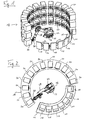
- Fig. 1 and 2 is a device according to the invention for verification and / or calibration of an occupant detection device of a vehicle seat 10 is shown.
- the device comprises a not shown Vehicle seat holder 11 for holding a plurality of vehicle seats 10.
- the vehicle seat mount 11 is for receiving designed by a maximum of seven vehicle seats 10. But it is the same possible to design the vehicle seat support 11 so that it more than can accommodate seven vehicle seats 10, or they are correspondingly smaller to dimension. Of course, it is in the one shown in Figs. 1 and 2 Embodiment also possible, the vehicle seat mount 11 with less than the maximum number of seven vehicle seats 10 too equip.
- the vehicle seats 10 received by the vehicle seat mount 11 are arranged side by side in a row. It is the turn of the Vehicle seats 10 curved such that the vehicle seats 10 a circle segment form, the angle in the illustrated embodiment approximately 110 °. Depending on the number of vehicle seats 10 or curvature of the Vehicle seat row may be the angle of the vehicle seat 10 described Circular segments also be greater or less than 110 °.
- vehicle seats 10 is in the illustrated embodiment around differently equipped seats of a model row or around different types of vehicle seats. But it is also conceivable one Arrangement of two or more similar vehicle seats in one Series to verify the measurements described below.
- the vehicle seats 10 are detachably connected to the vehicle seat mount 11.
- Each vehicle seat 10 may, for example be provided with a flange or adapter by means of a screw or locking connection to a trained accordingly Mating flange or mating adapter of the vehicle seat mount 11 can be fixed is.
- Each vehicle seat 10 is further provided with a to be checked and / or closed calibrating occupant detection device provided in the Area of the seat cushion 12 of the vehicle seat 10 arranged pressure sensor mat includes.
- the occupant detection device of each vehicle seat 10 communicates via a line 14 with an evaluation unit 16 (Fig. 3), which an evaluation of by the respective occupant detection device determined measured values.
- the device according to the invention has a child seat bearing 18 for storing a plurality of Child seats 20 on.
- the child seat bearing 18 comprises a shelf device, in the child seats 20 in several rows next to each other and are housed one above the other.
- the illustrated embodiment has the shelf device of the child seat bearing 18 three above the other arranged rows of twelve child seats 20, so it can a maximum of thirty six child seats 20 record.
- the capacity of the child seat bearing 18 completely to exploit i. There may also be fewer than thirty six child seats be housed in the child seat 18.
- the reverse is true also possible to provide a child seat bearing 18 with a larger capacity, for example, designed for a few hundred child seats 20 is.
- the child seat bearing 18 is curved and forms a circle segment, the Vehicle seat row is arranged opposite.
- the angle of the through Child seat bearing 18 formed circle segment is slightly more than 180 ° and its radius of curvature is slightly larger than the radius of curvature the vehicle seat row.
- the child seat bearing 18 and the row of vehicle seats 10 form in the illustrated embodiment about a circle, which is almost closed.
- a robot 22 is arranged, the one firmly anchored to the base base portion 24 and a working section 26, which is about a vertical axis through 360 ° relative to the base portion 24 is rotatable.
- the robot 22 covers with others Words a workspace of 360 °.
- the working section 22 comprises a freely movable in a vertical plane robot arm 28, at whose free end a freely movable in all directions Coupling / sensor head 30 is arranged.
- the coupling / sensor head 30 is used for coupling the robot 22 to the in the child seat 18 accommodated child seats 20 to these off to remove the child seat bearing 18. Both the coupling / sensor head 30 and the child seats 20 are for this purpose with appropriate Flanges or adapters equipped.
- the coupling / sensor head 30 comprises Furthermore, a load cell for measuring forces and torques, occur when the robot 22 a vehicle seat 10 with a child seat 20 is acted upon, as described in more detail below.
- a control unit 32 is provided which is connected via a line 33 to the robot 22.
- the control unit 32 not only serves for the mechanical control of the robot 22, but it also communicates with the coupling / sensor head 30 to pass through the Load cell of the coupling / sensor head 30 recorded measurement data receive and evaluate.
- the control unit 32 To consider the measurement data of the Load cell when checking or calibrating the occupant detection devices is the control unit 32 through a line 35 with the Evaluation unit 16 connected (Fig. 3).
- the review or calibration of the runs in the Vehicle seats 10 arranged occupant detection devices automatically from.
- the robot removes 22 by means of its coupling / sensor head 30, a first child seat 20 the child seat bearing 18 and presses it on the seat cushion 12 of a first Vehicle seat 10.
- the robot 22 presses the same child seat 20 to a second vehicle seat 10, then to a third vehicle seat 10 etc., until all of them are held in the vehicle seat mount 11 Vehicle seats 10 has taken place.
- the robot lays down 22 the child seat 20 again at its assigned location of the child seat bearing 18 and removes a second child seat 20, also successively placed on each vehicle seat 10. This procedure is repeated until each vehicle seat 10 at least once through each child seat 20 of the child seat bearing 18 has been acted upon.
- the pressing of the child seats 20 to the vehicle seats 10 takes place for each child seat 20 and each vehicle seat 10 according to a well-defined Scheme.
- the control unit 28th through a line 37 connected storage unit 34 information about the geometry of each child seat 20 and each vehicle seat 10 as well as about the forces and torques occurring in practice each possible or at least tested combination of child seat 20 and vehicle seat 10, which are used to control the robot 22 by the control unit 32 from the memory unit 34 accordingly can be retrieved.
- the robot 22 can put each child seat 20 with a force / torque combination on each vehicle seat 10, which corresponds exactly to the forces F 1 to F 4 (FIG. 4), when the child seat 20 is fastened to the vehicle seat 10 and occur at a certain occupancy of the child seat 20 as forces in a safety belt 36 and as a weight.
- F 1 to F 4 F 1 to F 4
- the robot 22 can put each child seat 20 with a force / torque combination on each vehicle seat 10, which corresponds exactly to the forces F 1 to F 4 (FIG. 4), when the child seat 20 is fastened to the vehicle seat 10 and occur at a certain occupancy of the child seat 20 as forces in a safety belt 36 and as a weight.
- the detected by the pressure sensor mat of the occupant detection device Measurements are made for each pair of child seat 20 or vehicle seat 10 evaluated in the evaluation unit 16 and with the corresponding applied force / torque combination correlated.
- the evaluation unit 16 is to this Purpose connected to the control unit 32 of the robot 22.
- the control unit 32, the memory unit 34 and the evaluation unit 16 can in be summarized a central processing unit.
- the evaluation unit 16 determines in which force / torque combinations the occupant detection device occupying the Vehicle seat 10 correctly detected or in which not. In case of a faulty Function of the occupant detection device can this accordingly be modified. Alternatively or additionally, a calibration the occupant recognition device are performed in total.
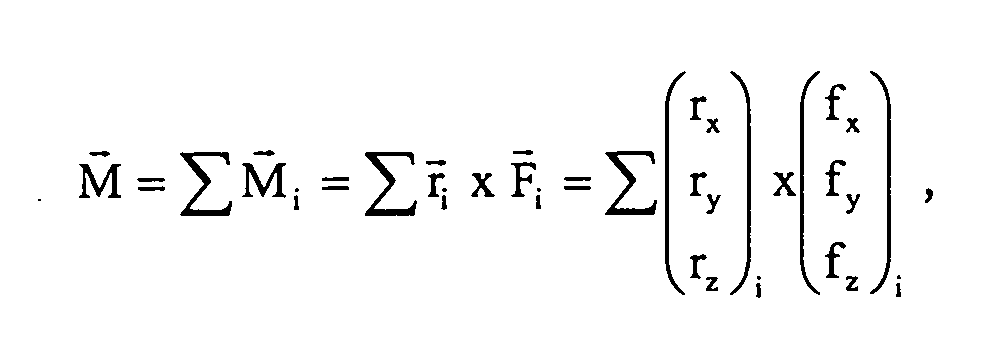
- a resultant force F and a resulting torque M which act in the center of gravity of the child seat 20 on this: wherein the vectors F i each represent the forces F 1 to F 4 and the vectors r i respectively the position of the forces F 1 to F 4 relative to the center of gravity of the child seat 20.
- An optimal simulation of all possible force / torque combinations all possible child seat / vehicle seat combinations is through a determination of all relevant force / torque combinations achieved for any child seat / vehicle seat combination.
Landscapes
- Engineering & Computer Science (AREA)
- Mechanical Engineering (AREA)
- Aviation & Aerospace Engineering (AREA)
- Transportation (AREA)
- General Health & Medical Sciences (AREA)
- Child & Adolescent Psychology (AREA)
- Health & Medical Sciences (AREA)
- Physics & Mathematics (AREA)
- General Physics & Mathematics (AREA)
- Seats For Vehicles (AREA)
- Automobile Manufacture Line, Endless Track Vehicle, Trailer (AREA)
- Air Bags (AREA)
- Geophysics And Detection Of Objects (AREA)
Abstract
Description
- Fig. 1
- eine perspektivische Ansicht einer erfindungsgemäßen Vorrichtung;
- Fig. 2
- eine Draufsicht auf die Vorrichtung von Fig. 1;
- Fig. 3
- eine schematische Draufsicht auf die Vorrichtung von Fig. 1;
- Fig. 4
- einen mittels eines Sicherheitsgurts an einem Fahrzeugsitz befestigten Kindersitz sowie die in dem Sicherheitsgurt auf- tretenden Spannungen und die Gewichtskraft; und
- Fig. 5
- ein Koordinatensystem zur mathematischen Abbildung der in Fig. 4 dargestellten Kräfte.

- 10
- Fahrzeugsitz
- 11
- Fahrzeugsitzhalterung
- 12
- Sitzpolster
- 14
- elektrische Leitung
- 16
- Auswerteeinheit
- 18
- Kindersitzlager
- 20
- Kindersitz
- 22
- Roboter
- 24
- Sockelabschnitt
- 26
- Arbeitsabschnitt
- 28
- Roboterarm
- 30
- Koppelsensorkopf
- 32
- Steuereinheit
- 33
- Leitung
- 34
- Speichereinheit
- 35
- Leitung
- 36
- Sicherheitsgurt
- 37
- Leitung
Claims (15)
- Vorrichtung zur Überprüfung und/oder Kalibrierung einer in einem Fahrzeugsitz (10) angeordneten Insassenerkennungseinrichtung miteinem Kindersitzlager (18) zur Aufbewahrung mindestens eines Kindersitzes (20),einer Fahrzeugsitzhalterung (11) zur Aufnahme mindestens eines Fahrzeugsitzes (10) undeinem Roboter (22), durch den ein im Kindersitzlager (18) gelagerter Kindersitz (20) aus dem Kindersitzlager (18) entnehmbar und an einen in der Fahrzeugsitzhalterung (11) gehaltenen Fahrzeugsitz (10) andrückbar ist.
- Vorrichtung nach Anspruch 1,
dadurch gekennzeichnet, dass
jeder Kindersitz (20) zur Simulation möglicher Einbaustellungen und/oder Sitzbelegungen des Kindersitzes (20) in verschiedenen vorbestimmten Relativpositionen bezüglich jedes Fahrzeugsitzes (10) und/oder unterschiedlich stark an diesen andrückbar ist. - Vorrichtung nach Anspruch 1 oder 2,
dadurch gekennzeichnet, dass
der Fahrzeugsitz (10) mit wenigstens einer vorbestimmten Kraft/Drehmoment-Kombination beaufschlagbar ist, die einer definierten Kombination aus Belegung des Kindersitzes (20) und Spannungen entspricht, welche bei einer Sicherung des Kindersitzes (20) am Fahrzeugsitz (10) in einem zur Sicherung verwendeten Gurt (36) auftreten. - Vorrichtung nach einem der vorherigen Ansprüche,
dadurch gekennzeichnet, dass
für unterschiedliche Kindersitze (20) jeweils mindestens eine, insbesondere fahrzeugsitzabhängige, Kraft/Drehmoment-Kombination in einer Speichereinheit (34) gespeichert ist. - Vorrichtung nach einem der vorherigen Ansprüche,
dadurch gekennzeichnet, dass
Angaben über die Geometrie jedes im Kindersitzlager (18) gelagerten Kindersitzes (20) und/oder Angaben über die Geometrie jedes in der Fahrzeugsitzhalterung aufgenommenen Fahrzeugsitzes (10) in einer Speichereinheit (34) gespeichert sind. - Vorrichtung nach einem der vorherigen Ansprüche,
dadurch gekennzeichnet, dass
der Roboter (22) einen Koppel-/Sensorkopf (26) zum Ankoppeln des Roboters (22) an den Kindersitz (20) und zum Messen von Kräften und Drehmomenten aufweist, die beim Andrücken des Kindersitzes (20) an den Fahrzeugsitz (10) auftreten. - Vorrichtung nach einem der vorherigen Ansprüche,
dadurch gekennzeichnet, dass
jeder Kindersitz (20) einen Flansch zur Ankopplung an den Roboter (22) aufweist. - Vorrichtung nach einem der vorherigen Ansprüche,
dadurch gekennzeichnet, dass
das Kindersitzlager (18) und/oder die Fahrzeugsitzhalterung (11) zumindest teilkreisförmig um den Roboter (22) herum angeordnet sind, und/oder dass der Roboter (22) einen Arbeitsbereich von 360° umfasst. - Vorrichtung nach einem der vorherigen Ansprüche,
dadurch gekennzeichnet, dass
das Kindersitzlager (18) eine Regaleinrichtung zur Aufnahme einer Vielzahl von Kindersitzen (20) aufweist und/oder dass mehrere Fahrzeugsitze (10) lösbar an der Fahrzeugsitzhalterung (11) befestigbar sind. - Verfahren zum Überprüfen und/oder Kalibrieren einer in einem Fahrzeugsitz (10) angeordneten Insassenerkennungseinrichtung, bei dem wenigstens ein Fahrzeugsitz (10) mit mindestens einem Kindersitz (20) beaufschlagt wird und jeweils eine entsprechende Reaktion der Insassenerkennungseinrichtung des Fahrzeugsitzes (10) ausgewertet wird, wobei die Beaufschlagung des Fahrzeugsitzes (10) durch den Kindersitz (20) mittels eines Roboters (22) erfolgt.
- Verfahren nach Anspruch 10,
dadurch gekennzeichnet, dass
eine vorbestimmte Kraft/Drehmoment-Kombination auf den Fahrzeugsitz (10) ausgeübt wird, die einer definierten Kombination aus Belegung des Kindersitzes (20) und Spannungen entspricht, welche bei einer Sicherung des Kindersitzes (20) am Fahrzeugsitz (10) in einem zur Sicherung verwendeten Gurt (36) auftreten. - Verfahren nach Anspruch 10 oder 11, dadurch gekennzeichnet, dass
durch jeden Kindersitz (20) mehrere vorbestimmte Kraft/ Drehmoment-Kombinationen auf den Fahrzeugsitz (10) ausgeübt werden. - Verfahren nach einem der Ansprüche 10 bis 12,
dadurch gekennzeichnet, dass
für unterschiedliche Kindersitze (20) jeweils mindestens eine, insbesondere fahrzeugsitzabhängige, Gurtspannung/ Sitzbelegungs-Kombination ermittelt wird und eine entsprechende, insbesondere fahrzeugsitzabhängige, Kraft/Drehmoment-Kombination errechnet und in einer Speichereinheit (34) abgespeichert wird. - Verfahren nach einem der Ansprüche 10 bis 13,
dadurch gekennzeichnet, dass
die Beaufschlagung des Fahrzeugsitzes (10) unter Berücksichtigung der jeweiligen, insbesondere in einer Speichereinheit (34) abgespeicherten, Kindersitzgeometrie und/oder Fahrzeugsitzgeometrie erfolgt. - Verfahren nach einem der Ansprüche 10 bis 14,
dadurch gekennzeichnet, dass
der Roboter (22) eine Vielzahl von Kindersitzen (20) nacheinander aus dem Kindersitzlager (18) entnimmt und jeweils jeden Fahrzeugsitz (10) damit beaufschlagt.
Priority Applications (5)
| Application Number | Priority Date | Filing Date | Title |
|---|---|---|---|
| AT04014871T ATE357354T1 (de) | 2004-06-24 | 2004-06-24 | Vorrichtung und verfahren zum überprüfen und/oder kalibrieren einer in einem fahrzeugsitz angeordneten insassenerkennungseinrichtung |
| EP04014871A EP1609663B1 (de) | 2004-06-24 | 2004-06-24 | Vorrichtung und Verfahren zum Überprüfen und/oder Kalibrieren einer in einem Fahrzeugsitz angeordneten Insassenerkennungseinrichtung |
| DE502004003279T DE502004003279D1 (de) | 2004-06-24 | 2004-06-24 | Vorrichtung und Verfahren zum Überprüfen und/oder Kalibrieren einer in einem Fahrzeugsitz angeordneten Insassenerkennungseinrichtung |
| US11/158,748 US7574892B2 (en) | 2004-06-24 | 2005-06-22 | Device and method for checking and/or calibrating a passenger recognition device arranged in a vehicle seat |
| US12/482,508 US7818989B2 (en) | 2004-06-24 | 2009-06-11 | Device and method for checking and/or calibrating a passenger recognition device arranged in a vehicle seat |
Applications Claiming Priority (1)
| Application Number | Priority Date | Filing Date | Title |
|---|---|---|---|
| EP04014871A EP1609663B1 (de) | 2004-06-24 | 2004-06-24 | Vorrichtung und Verfahren zum Überprüfen und/oder Kalibrieren einer in einem Fahrzeugsitz angeordneten Insassenerkennungseinrichtung |
Publications (2)
| Publication Number | Publication Date |
|---|---|
| EP1609663A1 true EP1609663A1 (de) | 2005-12-28 |
| EP1609663B1 EP1609663B1 (de) | 2007-03-21 |
Family
ID=34925478
Family Applications (1)
| Application Number | Title | Priority Date | Filing Date |
|---|---|---|---|
| EP04014871A Expired - Lifetime EP1609663B1 (de) | 2004-06-24 | 2004-06-24 | Vorrichtung und Verfahren zum Überprüfen und/oder Kalibrieren einer in einem Fahrzeugsitz angeordneten Insassenerkennungseinrichtung |
Country Status (4)
| Country | Link |
|---|---|
| US (2) | US7574892B2 (de) |
| EP (1) | EP1609663B1 (de) |
| AT (1) | ATE357354T1 (de) |
| DE (1) | DE502004003279D1 (de) |
Families Citing this family (2)
| Publication number | Priority date | Publication date | Assignee | Title |
|---|---|---|---|---|
| US9891130B2 (en) * | 2015-06-09 | 2018-02-13 | Ford Global Technologies, Llc | System and method for testing seat pressure sensor |
| DE102019128264B3 (de) * | 2019-10-21 | 2021-02-11 | Audi Ag | Verfahren sowie Prüfanordnung zur Funktionsprüfung einer Sitzbelegungserkennung eines Fahrzeugsitzes |
Citations (4)
| Publication number | Priority date | Publication date | Assignee | Title |
|---|---|---|---|---|
| US4908777A (en) * | 1988-01-27 | 1990-03-13 | Storage Technology Corporation | Robot arm calibration system |
| US6020812A (en) * | 1995-06-26 | 2000-02-01 | Breed Automotive Technologies, Inc. | Vehicle occupant sensing system |
| US20030040858A1 (en) * | 2000-05-10 | 2003-02-27 | Wallace Michael W. | Vehicle occupant classification system and method |
| US20030120379A1 (en) * | 2001-12-20 | 2003-06-26 | Storage Technology Corporation | Barcode dual laser scanner targeting |
Family Cites Families (14)
| Publication number | Priority date | Publication date | Assignee | Title |
|---|---|---|---|---|
| US5703303A (en) * | 1996-12-19 | 1997-12-30 | Lear Corporation | Method and system for wear testing a seat by simulating human seating activity and robotic human body simulator for use therein |
| US6539771B1 (en) * | 2000-05-12 | 2003-04-01 | Delphi Technologies, Inc. | Seat sensor calibration method and system |
| DE10132110B4 (de) * | 2000-07-05 | 2011-06-30 | DENSO CORPORATION, Aichi-pref. | Verfahren zum Eichen der Empfindlichkeit von druckerfassenden Zellen eines Fahrzeugpassagiersitzes |
| US20020002854A1 (en) * | 2000-07-05 | 2002-01-10 | Yuzo Imoto | Vehicle passenger distinguishment system with sensor cells installed inside seat |
| US6578870B2 (en) * | 2000-07-12 | 2003-06-17 | Siemens Ag | Vehicle occupant weight classification system |
| DE10039774C1 (de) * | 2000-08-16 | 2002-01-24 | Bosch Gmbh Robert | Verfahren zur Vermessung einer Sitzmatte für einen Fahrzeugsitz |
| US20020066302A1 (en) * | 2000-12-05 | 2002-06-06 | Hamm James R. | Seat sensor calibration system and related method |
| US6479766B2 (en) * | 2001-03-26 | 2002-11-12 | Delphi Technologies, Inc. | Seat occupant weight detection system having compensation for seat aging and usage |
| US7046158B2 (en) * | 2002-04-17 | 2006-05-16 | Darrel Saunders | Method and apparatus for sensing seat occupancy |
| JP3749936B2 (ja) * | 2002-10-02 | 2006-03-01 | 株式会社デンソー | 車両乗員検知装置及びその調整方法 |
| JP3682039B2 (ja) * | 2002-10-02 | 2005-08-10 | 株式会社デンソー | 車両乗員検知装置 |
| US6832503B2 (en) * | 2002-12-18 | 2004-12-21 | Lear Corporation | Machine for testing occupant restraint system |
| US6985077B2 (en) * | 2003-12-30 | 2006-01-10 | Lear Corporation | Method of tuning a sensor array for occupancy sensing in a vehicle seat |
| US7363184B2 (en) * | 2005-02-09 | 2008-04-22 | Trw Automotive U.S. Llc | System and method for drift compensation in a seat load sensing system |
-
2004
- 2004-06-24 AT AT04014871T patent/ATE357354T1/de not_active IP Right Cessation
- 2004-06-24 DE DE502004003279T patent/DE502004003279D1/de not_active Expired - Fee Related
- 2004-06-24 EP EP04014871A patent/EP1609663B1/de not_active Expired - Lifetime
-
2005
- 2005-06-22 US US11/158,748 patent/US7574892B2/en not_active Expired - Fee Related
-
2009
- 2009-06-11 US US12/482,508 patent/US7818989B2/en not_active Expired - Lifetime
Patent Citations (4)
| Publication number | Priority date | Publication date | Assignee | Title |
|---|---|---|---|---|
| US4908777A (en) * | 1988-01-27 | 1990-03-13 | Storage Technology Corporation | Robot arm calibration system |
| US6020812A (en) * | 1995-06-26 | 2000-02-01 | Breed Automotive Technologies, Inc. | Vehicle occupant sensing system |
| US20030040858A1 (en) * | 2000-05-10 | 2003-02-27 | Wallace Michael W. | Vehicle occupant classification system and method |
| US20030120379A1 (en) * | 2001-12-20 | 2003-06-26 | Storage Technology Corporation | Barcode dual laser scanner targeting |
Also Published As
| Publication number | Publication date |
|---|---|
| US20090249857A1 (en) | 2009-10-08 |
| ATE357354T1 (de) | 2007-04-15 |
| EP1609663B1 (de) | 2007-03-21 |
| DE502004003279D1 (de) | 2007-05-03 |
| US7574892B2 (en) | 2009-08-18 |
| US20060009877A1 (en) | 2006-01-12 |
| US7818989B2 (en) | 2010-10-26 |
Similar Documents
| Publication | Publication Date | Title |
|---|---|---|
| DE102011053325B4 (de) | Prüfstand für die dynamische Überprüfung einer einzelnen Fahrwerkskomponente oder eines vollständigen Achssystems eines Kraftfahrzeugs, sowie Verfahren zum Überprüfen auf Selbigem | |
| EP0358003B1 (de) | Anordnung zur Diagnose der Abmessungen einer Kfz-Karosserie | |
| DE3620391A1 (de) | Vorrichtung zur loesbaren verbindung eines werkzeuges, greifers, messgeraetes oder anderen wirksystems mit dem arm eines roboters oder dergleichen | |
| DE3213319A1 (de) | Einrichtung zum messen von kraft- und momentkomponenten in mehreren richtungen | |
| WO2020120303A1 (de) | Befestigungsanordnung zum befestigen eines prüfvorrichtungshalters an einer kraftmesseinrichtung, kraftmesseinrichtung mit einer solchen befestigungsanordnung; prüfvorrichtungshalter, und schlittenteil für eine kraftmesseinrichtung | |
| EP2112458B1 (de) | Verfahren und Vorrichtung zur Prüfung der Maßgenauigkeiten von Trommelbremsbelägen | |
| DE19749230A1 (de) | Spannvorrichtung | |
| EP1832540B1 (de) | Messvorrichtung für eine Treibfähigkeitsmessung | |
| DE102022205323B4 (de) | Fahrzeugfesselung für einen Prüfstand | |
| EP1609663B1 (de) | Vorrichtung und Verfahren zum Überprüfen und/oder Kalibrieren einer in einem Fahrzeugsitz angeordneten Insassenerkennungseinrichtung | |
| DE20304869U1 (de) | Prüf- und Einstellvorrichtung | |
| DE2738609C2 (de) | Prüf- und MeBlehre zum Feststellen von Verformungen des Rahmens von Motorrädern | |
| DE19822922B4 (de) | Prüfstand für ein Kraftfahrzeug | |
| DE19941005A1 (de) | Gurtkraft-Meßanordnung | |
| DE69404596T2 (de) | Vorrichtung zum Einbau eines Sitzes in die Karosserie eines Automobils | |
| EP0766075B1 (de) | Verfahren zur gleichzeitigen Prüfung von mehreren Kraftaufnehmern, insbesondere Wägezellen, mit einer Drucklast | |
| DE20107590U1 (de) | Vorrichtung zur Positionierung einer Testpuppe in einem Versuchsaufbau für aufblasbare Schutzkissen in Fahrzeugen | |
| DE102016219023B4 (de) | Positioniereinrichtung für ein Kraftfahrzeug, Verwendung einer solchen Positioniereinrichtung und Verfahren zum Überprüfen eines Kraftfahrzeugs | |
| DE202015105541U1 (de) | Robotermesszelle | |
| DE102023116571B3 (de) | Vorrichtung zur Befestigung von mobilen Inspektionsmitteln an Inspektionsgegenständen, Anordnung umfassend eine solche Vorrichtung und Verwendung einer solchen Vorrichtung bei der Inspektion von Flugzeugtriebwerken oder Teilen davon | |
| EP3879252A1 (de) | Prüfverfahren und prüfvorrichtung, anlernverfahren | |
| DE3241534C1 (de) | Meßmaschine zum Messen des Außendurchmessers zylindrischer Werkstücke sowie der Umfangslänge und der Teilflächen- Schieflage halbzylindrischer Werkstücke | |
| EP1571411B1 (de) | Messeinrichtung | |
| DE29918490U1 (de) | Profilierte Laufrolle für einen Fahrzeugprüfstand | |
| DE102023131735B3 (de) | Vorrichtung zur krafteinleitung in ein test-fahrzeug sowie prüfstand |
Legal Events
| Date | Code | Title | Description |
|---|---|---|---|
| PUAI | Public reference made under article 153(3) epc to a published international application that has entered the european phase |
Free format text: ORIGINAL CODE: 0009012 |
|
| 17P | Request for examination filed |
Effective date: 20050114 |
|
| AK | Designated contracting states |
Kind code of ref document: A1 Designated state(s): AT BE BG CH CY CZ DE DK EE ES FI FR GB GR HU IE IT LI LU MC NL PL PT RO SE SI SK TR |
|
| AX | Request for extension of the european patent |
Extension state: AL HR LT LV MK |
|
| AKX | Designation fees paid |
Designated state(s): AT BE BG CH CY CZ DE DK EE ES FI FR GB GR HU IE IT LI LU MC NL PL PT RO SE SI SK TR |
|
| GRAP | Despatch of communication of intention to grant a patent |
Free format text: ORIGINAL CODE: EPIDOSNIGR1 |
|
| GRAS | Grant fee paid |
Free format text: ORIGINAL CODE: EPIDOSNIGR3 |
|
| GRAA | (expected) grant |
Free format text: ORIGINAL CODE: 0009210 |
|
| AK | Designated contracting states |
Kind code of ref document: B1 Designated state(s): AT BE BG CH CY CZ DE DK EE ES FI FR GB GR HU IE IT LI LU MC NL PL PT RO SE SI SK TR |
|
| PG25 | Lapsed in a contracting state [announced via postgrant information from national office to epo] |
Ref country code: IE Free format text: LAPSE BECAUSE OF FAILURE TO SUBMIT A TRANSLATION OF THE DESCRIPTION OR TO PAY THE FEE WITHIN THE PRESCRIBED TIME-LIMIT Effective date: 20070321 Ref country code: PL Free format text: LAPSE BECAUSE OF FAILURE TO SUBMIT A TRANSLATION OF THE DESCRIPTION OR TO PAY THE FEE WITHIN THE PRESCRIBED TIME-LIMIT Effective date: 20070321 Ref country code: FI Free format text: LAPSE BECAUSE OF FAILURE TO SUBMIT A TRANSLATION OF THE DESCRIPTION OR TO PAY THE FEE WITHIN THE PRESCRIBED TIME-LIMIT Effective date: 20070321 Ref country code: NL Free format text: LAPSE BECAUSE OF FAILURE TO SUBMIT A TRANSLATION OF THE DESCRIPTION OR TO PAY THE FEE WITHIN THE PRESCRIBED TIME-LIMIT Effective date: 20070321 Ref country code: SI Free format text: LAPSE BECAUSE OF FAILURE TO SUBMIT A TRANSLATION OF THE DESCRIPTION OR TO PAY THE FEE WITHIN THE PRESCRIBED TIME-LIMIT Effective date: 20070321 |
|
| REG | Reference to a national code |
Ref country code: GB Ref legal event code: FG4D Free format text: NOT ENGLISH |
|
| REG | Reference to a national code |
Ref country code: CH Ref legal event code: EP |
|
| REF | Corresponds to: |
Ref document number: 502004003279 Country of ref document: DE Date of ref document: 20070503 Kind code of ref document: P |
|
| REG | Reference to a national code |
Ref country code: IE Ref legal event code: FG4D Free format text: LANGUAGE OF EP DOCUMENT: GERMAN |
|
| PG25 | Lapsed in a contracting state [announced via postgrant information from national office to epo] |
Ref country code: SE Free format text: LAPSE BECAUSE OF FAILURE TO SUBMIT A TRANSLATION OF THE DESCRIPTION OR TO PAY THE FEE WITHIN THE PRESCRIBED TIME-LIMIT Effective date: 20070621 |
|
| PG25 | Lapsed in a contracting state [announced via postgrant information from national office to epo] |
Ref country code: ES Free format text: LAPSE BECAUSE OF FAILURE TO SUBMIT A TRANSLATION OF THE DESCRIPTION OR TO PAY THE FEE WITHIN THE PRESCRIBED TIME-LIMIT Effective date: 20070702 |
|
| PG25 | Lapsed in a contracting state [announced via postgrant information from national office to epo] |
Ref country code: PT Free format text: LAPSE BECAUSE OF FAILURE TO SUBMIT A TRANSLATION OF THE DESCRIPTION OR TO PAY THE FEE WITHIN THE PRESCRIBED TIME-LIMIT Effective date: 20070821 |
|
| NLV1 | Nl: lapsed or annulled due to failure to fulfill the requirements of art. 29p and 29m of the patents act | ||
| GBV | Gb: ep patent (uk) treated as always having been void in accordance with gb section 77(7)/1977 [no translation filed] |
Effective date: 20070321 |
|
| REG | Reference to a national code |
Ref country code: IE Ref legal event code: FD4D |
|
| PG25 | Lapsed in a contracting state [announced via postgrant information from national office to epo] |
Ref country code: GB Free format text: LAPSE BECAUSE OF FAILURE TO SUBMIT A TRANSLATION OF THE DESCRIPTION OR TO PAY THE FEE WITHIN THE PRESCRIBED TIME-LIMIT Effective date: 20070321 Ref country code: SK Free format text: LAPSE BECAUSE OF FAILURE TO SUBMIT A TRANSLATION OF THE DESCRIPTION OR TO PAY THE FEE WITHIN THE PRESCRIBED TIME-LIMIT Effective date: 20070321 |
|
| BERE | Be: lapsed |
Owner name: DELPHI TECHNOLOGIES, INC. Effective date: 20070630 |
|
| PG25 | Lapsed in a contracting state [announced via postgrant information from national office to epo] |
Ref country code: RO Free format text: LAPSE BECAUSE OF FAILURE TO SUBMIT A TRANSLATION OF THE DESCRIPTION OR TO PAY THE FEE WITHIN THE PRESCRIBED TIME-LIMIT Effective date: 20070321 Ref country code: CZ Free format text: LAPSE BECAUSE OF FAILURE TO SUBMIT A TRANSLATION OF THE DESCRIPTION OR TO PAY THE FEE WITHIN THE PRESCRIBED TIME-LIMIT Effective date: 20070321 |
|
| PLBE | No opposition filed within time limit |
Free format text: ORIGINAL CODE: 0009261 |
|
| STAA | Information on the status of an ep patent application or granted ep patent |
Free format text: STATUS: NO OPPOSITION FILED WITHIN TIME LIMIT |
|
| PG25 | Lapsed in a contracting state [announced via postgrant information from national office to epo] |
Ref country code: MC Free format text: LAPSE BECAUSE OF NON-PAYMENT OF DUE FEES Effective date: 20070630 Ref country code: DK Free format text: LAPSE BECAUSE OF FAILURE TO SUBMIT A TRANSLATION OF THE DESCRIPTION OR TO PAY THE FEE WITHIN THE PRESCRIBED TIME-LIMIT Effective date: 20070321 |
|
| 26N | No opposition filed |
Effective date: 20071227 |
|
| PG25 | Lapsed in a contracting state [announced via postgrant information from national office to epo] |
Ref country code: BE Free format text: LAPSE BECAUSE OF NON-PAYMENT OF DUE FEES Effective date: 20070630 |
|
| PG25 | Lapsed in a contracting state [announced via postgrant information from national office to epo] |
Ref country code: GR Free format text: LAPSE BECAUSE OF FAILURE TO SUBMIT A TRANSLATION OF THE DESCRIPTION OR TO PAY THE FEE WITHIN THE PRESCRIBED TIME-LIMIT Effective date: 20070622 |
|
| PG25 | Lapsed in a contracting state [announced via postgrant information from national office to epo] |
Ref country code: AT Free format text: LAPSE BECAUSE OF NON-PAYMENT OF DUE FEES Effective date: 20070624 |
|
| PG25 | Lapsed in a contracting state [announced via postgrant information from national office to epo] |
Ref country code: EE Free format text: LAPSE BECAUSE OF FAILURE TO SUBMIT A TRANSLATION OF THE DESCRIPTION OR TO PAY THE FEE WITHIN THE PRESCRIBED TIME-LIMIT Effective date: 20070321 |
|
| REG | Reference to a national code |
Ref country code: CH Ref legal event code: PL |
|
| PG25 | Lapsed in a contracting state [announced via postgrant information from national office to epo] |
Ref country code: LI Free format text: LAPSE BECAUSE OF NON-PAYMENT OF DUE FEES Effective date: 20080630 Ref country code: CH Free format text: LAPSE BECAUSE OF NON-PAYMENT OF DUE FEES Effective date: 20080630 |
|
| PG25 | Lapsed in a contracting state [announced via postgrant information from national office to epo] |
Ref country code: CY Free format text: LAPSE BECAUSE OF FAILURE TO SUBMIT A TRANSLATION OF THE DESCRIPTION OR TO PAY THE FEE WITHIN THE PRESCRIBED TIME-LIMIT Effective date: 20070321 |
|
| PG25 | Lapsed in a contracting state [announced via postgrant information from national office to epo] |
Ref country code: BG Free format text: LAPSE BECAUSE OF FAILURE TO SUBMIT A TRANSLATION OF THE DESCRIPTION OR TO PAY THE FEE WITHIN THE PRESCRIBED TIME-LIMIT Effective date: 20070621 Ref country code: LU Free format text: LAPSE BECAUSE OF NON-PAYMENT OF DUE FEES Effective date: 20070624 |
|
| PGFP | Annual fee paid to national office [announced via postgrant information from national office to epo] |
Ref country code: IT Payment date: 20090622 Year of fee payment: 6 |
|
| PG25 | Lapsed in a contracting state [announced via postgrant information from national office to epo] |
Ref country code: TR Free format text: LAPSE BECAUSE OF FAILURE TO SUBMIT A TRANSLATION OF THE DESCRIPTION OR TO PAY THE FEE WITHIN THE PRESCRIBED TIME-LIMIT Effective date: 20070321 Ref country code: HU Free format text: LAPSE BECAUSE OF FAILURE TO SUBMIT A TRANSLATION OF THE DESCRIPTION OR TO PAY THE FEE WITHIN THE PRESCRIBED TIME-LIMIT Effective date: 20070922 |
|
| PGFP | Annual fee paid to national office [announced via postgrant information from national office to epo] |
Ref country code: DE Payment date: 20090619 Year of fee payment: 6 |
|
| REG | Reference to a national code |
Ref country code: FR Ref legal event code: ST Effective date: 20110228 |
|
| PG25 | Lapsed in a contracting state [announced via postgrant information from national office to epo] |
Ref country code: IT Free format text: LAPSE BECAUSE OF NON-PAYMENT OF DUE FEES Effective date: 20100624 |
|
| PG25 | Lapsed in a contracting state [announced via postgrant information from national office to epo] |
Ref country code: DE Free format text: LAPSE BECAUSE OF NON-PAYMENT OF DUE FEES Effective date: 20110101 |
|
| PG25 | Lapsed in a contracting state [announced via postgrant information from national office to epo] |
Ref country code: FR Free format text: LAPSE BECAUSE OF NON-PAYMENT OF DUE FEES Effective date: 20100630 |
|
| PGFP | Annual fee paid to national office [announced via postgrant information from national office to epo] |
Ref country code: FR Payment date: 20090611 Year of fee payment: 6 |