EP1609702A1 - Structure de panneau de plancher et carrosserie du véhicule ainsi équipée - Google Patents
Structure de panneau de plancher et carrosserie du véhicule ainsi équipée Download PDFInfo
- Publication number
- EP1609702A1 EP1609702A1 EP05013362A EP05013362A EP1609702A1 EP 1609702 A1 EP1609702 A1 EP 1609702A1 EP 05013362 A EP05013362 A EP 05013362A EP 05013362 A EP05013362 A EP 05013362A EP 1609702 A1 EP1609702 A1 EP 1609702A1
- Authority
- EP
- European Patent Office
- Prior art keywords
- area
- rigidity
- weight
- heavy
- panel
- Prior art date
- Legal status (The legal status is an assumption and is not a legal conclusion. Google has not performed a legal analysis and makes no representation as to the accuracy of the status listed.)
- Withdrawn
Links
- 230000002093 peripheral effect Effects 0.000 claims abstract description 100
- 238000013016 damping Methods 0.000 claims description 123
- 239000000463 material Substances 0.000 claims description 114
- 239000010426 asphalt Substances 0.000 claims description 31
- 239000011324 bead Substances 0.000 claims description 30
- 230000005484 gravity Effects 0.000 claims description 11
- 230000009467 reduction Effects 0.000 description 72
- 230000000694 effects Effects 0.000 description 34
- 238000005452 bending Methods 0.000 description 22
- 239000000725 suspension Substances 0.000 description 17
- 230000005540 biological transmission Effects 0.000 description 12
- 238000004519 manufacturing process Methods 0.000 description 11
- 229910000831 Steel Inorganic materials 0.000 description 8
- 239000010959 steel Substances 0.000 description 8
- 239000003973 paint Substances 0.000 description 6
- 230000008859 change Effects 0.000 description 5
- 230000003014 reinforcing effect Effects 0.000 description 5
- 239000000853 adhesive Substances 0.000 description 4
- 230000001070 adhesive effect Effects 0.000 description 4
- 239000002184 metal Substances 0.000 description 4
- 238000010422 painting Methods 0.000 description 4
- 150000001768 cations Chemical class 0.000 description 3
- 238000009826 distribution Methods 0.000 description 2
- 230000000452 restraining effect Effects 0.000 description 2
- 238000005476 soldering Methods 0.000 description 2
- 238000003466 welding Methods 0.000 description 2
- OKTJSMMVPCPJKN-UHFFFAOYSA-N Carbon Chemical compound [C] OKTJSMMVPCPJKN-UHFFFAOYSA-N 0.000 description 1
- 238000010521 absorption reaction Methods 0.000 description 1
- 125000003647 acryloyl group Chemical group O=C([*])C([H])=C([H])[H] 0.000 description 1
- 230000000052 comparative effect Effects 0.000 description 1
- 239000002131 composite material Substances 0.000 description 1
- 230000007423 decrease Effects 0.000 description 1
- 230000003247 decreasing effect Effects 0.000 description 1
- 230000001419 dependent effect Effects 0.000 description 1
- 239000000839 emulsion Substances 0.000 description 1
- 210000003608 fece Anatomy 0.000 description 1
- 238000003754 machining Methods 0.000 description 1
- 230000004048 modification Effects 0.000 description 1
- 238000012986 modification Methods 0.000 description 1
- 230000001629 suppression Effects 0.000 description 1
- 230000002889 sympathetic effect Effects 0.000 description 1
- XLYOFNOQVPJJNP-UHFFFAOYSA-N water Substances O XLYOFNOQVPJJNP-UHFFFAOYSA-N 0.000 description 1
Images







Classifications
-
- B—PERFORMING OPERATIONS; TRANSPORTING
- B62—LAND VEHICLES FOR TRAVELLING OTHERWISE THAN ON RAILS
- B62D—MOTOR VEHICLES; TRAILERS
- B62D25/00—Superstructure or monocoque structure sub-units; Parts or details thereof not otherwise provided for
- B62D25/20—Floors or bottom sub-units
-
- B—PERFORMING OPERATIONS; TRANSPORTING
- B60—VEHICLES IN GENERAL
- B60R—VEHICLES, VEHICLE FITTINGS, OR VEHICLE PARTS, NOT OTHERWISE PROVIDED FOR
- B60R13/00—Elements for body-finishing, identifying, or decorating; Arrangements or adaptations for advertising purposes
- B60R13/08—Insulating elements, e.g. for sound insulation
- B60R13/0815—Acoustic or thermal insulation of passenger compartments
- B60R13/083—Acoustic or thermal insulation of passenger compartments for fire walls or floors
-
- B—PERFORMING OPERATIONS; TRANSPORTING
- B62—LAND VEHICLES FOR TRAVELLING OTHERWISE THAN ON RAILS
- B62D—MOTOR VEHICLES; TRAILERS
- B62D25/00—Superstructure or monocoque structure sub-units; Parts or details thereof not otherwise provided for
- B62D25/20—Floors or bottom sub-units
- B62D25/2009—Floors or bottom sub-units in connection with other superstructure subunits
- B62D25/2036—Floors or bottom sub-units in connection with other superstructure subunits the subunits being side panels, sills or pillars
Definitions
- the present invention relates to a floor panel structure of a vehicle body and to a vehicle body provided therewith, particularly to a floor panel structure of a vehicle body in which a floor of an automotive vehicle is formed by a floor panel coupled to a plurality of frame members which extend in substantially longitudinal and width directions of the vehicle body.
- vibration from frame members coupled to the engine or the suspension of the vehicle is transmitted to floor panels and makes the floor panels and air in the cabin vibrate, resulting in uncomfortable vibration and noises being generated in the cabin.
- vibration of engine itself and the road noise from the suspension are considered as vibration resources primarily.
- the road noise is generally caused by resonance of vehicle tires and sympathetic vibration of the suspension.
- damping materials or the like which are applied to the floor panels or the particular portions of the vehicle body have been generally used to suppress such vibration and noises.
- a large amount of these materials are generally required, and thereby the weight of the vehicle body tends to increase improperly. This overweight would cause various disadvantages including an issue of costs.
- Japanese Patent Laid-Open Publication No. 6-107235 discloses a panel structure of a vehicle body in which a panel comprises a plurality of projecting portions with shell structure, which has a proper strength in bending, compressing and tensioning, and recess portions extending between the projecting portions.
- the vibration generated could be increased at the recess portions primarily, and the increased vibration could be reduced properly by damping materials provided at the recess portions.
- the above-described projecting portions formed at the floor are required to be disposed with their proper height and location which will not interference with these objects. Further, the height of the projecting portions needs to be set properly so as to provide the passengers with comfortable stepping. Also, those projecting portions need to be formed properly within floor panels enclosed by the frame members.
- the vehicle body panel structure disclosed in the above-described patent publication could not reduce the vibration properly.
- the present invention has been devised in view of the above-described problems of the conventional structure, and an object of the present invention is to provide a floor panel structure of a vehicle body and a vehicle body which can reduce properly the vibration energy transmitted from the frame members to the floor panel and thereby reduce the acoustic emission generated from the floor panel.
- a floor panel structure of a vehicle body in which a floor of an automotive vehicle is to be formed by a floor panel coupled to a plurality of frame members which extend in substantially longitudinal and width directions of the vehicle, comprising:
- a floor panel structure of a vehicle body in which a floor of an automotive vehicle is formed by a floor panel coupled to a plurality of frame members which extend in substantially longitudinal and width directions of the vehicle, comprising a panel area provided at the floor panel, the panel area being formed by being enclosed at least by the frame member, a heavy-weight area formed within the panel area, the heavy-weight area being located at a substantially central portion of the panel area, a peripheral area formed within the panel area, the peripheral area being located substantially around the heavy-weight area, wherein the heavy-weight area is configured so as to be heavier than the peripheral area.
- said first area is a heavy-weight area which comprises a plate which is thicker than that of said peripheral area, whereby said heavy-weight area is configured so as to be heavier than said peripheral area.
- the heavy-weight area comprises a plate which is thicker than that of the peripheral area, whereby the heavy-weight area is configured so as to be heavier than the peripheral area.
- said first area is a heavy-weight area which comprises an opening portion which includes a through hole and a plug which is applied so as to at least partly close the through hole, and said plug preferably comprises a plate which is thicker than the floor panel comprising said peripheral area.
- the heavy-weight area comprises an opening portion which includes a through hole and a plug which is applied so as to close the through hole, and the plug comprises a plate which is thicker than the floor panel comprising the peripheral area.
- the heavy-weight area comprises the plug applied to the through hole and the weight of the heavy-weight area is adjustable by controlling the thickness of the plug, the weight of the heavy-weight area can be increased easily and properly, so that the vibration energy can be increased surely at the peripheral area.
- the opening portion further comprises a difference-in-level portion which projects substantially downward, and the through hole is formed at the difference-in-level portion. According to this structure, since the through hole is formed at the difference-in-level portion projecting downward, for example, excessive paints can be easily and properly drained from the through hole in painting manufacturing process of the vehicle.
- the first or heavy-weight area comprises the application-type of damping material which is provided at the substantially central portion of the panel area, and the asphalt-based damping material is provided at the peripheral area having a lower hardness and/or a greater specific gravity than that of the application-type of damping material provided at the first or heavy-weight area, whereby the first or heavy-weight area preferably is configured so as to be heavier than the peripheral area.
- the vibration energy at the panel area can be further reduced by the vibration damping function of the application-type of damping material and the asphalt-based damping material themselves.
- the heavy-weight area has a higher rigidity than the peripheral area.
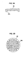
- FIG. 3A is a sectional view of a first modified example of a plug according to the first embodiment of the present invention
- FIG. 3B is a plan view of a second modified example of the plug according to the first embodiment of the present invention.
- FIG. 5A is a sectional view of a modified example of the second embodiment of the present invention
- FIG. 5B is a sectional view taken along line V-V of FIG. 5A, illustrating a sectional structure of the modified example in the vehicle width direction of the vehicle.
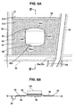
- FIG. 6A is an enlarged plan view of a panel area S13 according to the third embodiment of the present invention
- FIG. 6B is a sectional view taken along line VI-VI of FIG. 6A, illustrating a sectional structure of the panel area S13 in the longitudinal direction of the vehicle.
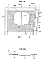
- FIG. 7A is an enlarged plan view of a panel area S15 according to the third embodiment of the present invention
- FIG. 7B is a sectional view taken along line VII-VII of FIG. 7A, illustrating a sectional structure of the panel area S15 in the longitudinal direction of the vehicle.
- FIG. 8A is a graph showing rigidity distribution of a high-rigidity area and a low-rigidity area of a floor panel according to a comparative sample
- FIG. 8B is a graph showing rigidity distribution of the high-rigidity area and the low-rigidity area of the floor panel according to the third embodiment of the present invention.
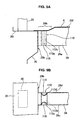
- FIG. 9A is a partially enlarged elevation view of a No. 4 cross member along with a side sill and a pillar, viewed from the front of the vehicle, according to the fourth embodiment of the present invention
- FIG. 9B is a partially enlarged plan view of them, viewed from above, according to the fourth embodiment of the present invention.
- FIG. 10A is a partially enlarged elevation view of a modified No. 4 cross member along with the side sill and the pillar, viewed from the front of the vehicle, according to the fourth embodiment of the present invention
- FIG. 10B is a partially enlarged plan view of them, viewed from above, according to the fourth embodiment of the present invention.
- FIG. 12A is an enlarged plan view of the No. 4 cross member and a panel area S11 according to the fourth embodiment of the present invention
- FIG. 12B is a sectional view taken along line XII-XII of FIG. 12A, illustrating a sectional structure of the panel area S11 in the vehicle width direction.
- FIG. 13A is a schematic view of frame members for explaining the function of the fourth embodiment of the present invention
- FIG. 13B is a schematic view illustrating a deformation state of the vehicle body structure including an upper body.
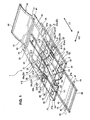
- FIG. 1 is a perspective view of an underbody of an automotive vehicle according to the first through fourth embodiments of the present invention.
- an underbody 1 of the automotive vehicle comprises a plurality of frame members, and a plurality of floor panels 2, 4, 6, 8, 10, 12, 14 and 16, which constitute a floor portion of a cabin, which are coupled to these frame members.
- the frame members will be described referring to FIG. 1.
- the frame members as illustrated in FIG. 1, a pair of front side frames 18, side sills 20, floor side frames 22, rear side frames 24, which extend substantially in a longitudinal direction LD of the vehicle, No. 1 through No. 9 cross members 26 to 34 which extend substantially in a vehicle width direction WD, and No. 1 through No. 3 tunnel side members 36 through 38 which extend substantially in the longitudinal direction LD between the cross members.
- a pair of front side frames 18 preferably having a substantially closed cross section is provided at or near the front portion of the underbody 1 of the vehicle so as to extend substantially in the longitudinal direction LD and at least partly enclose an engine room from the both sides.
- a No. 1 cross member 26 preferably having a substantially closed cross section, a reinforced member extending substantially in the vehicle width direction WD, is connected to front ends of the front side frames 18. Further, to the front side frames are or are to be respectively attached an engine 40 and a front suspension cross member 42, and front suspensions 44 are supported at the front suspension cross member 42.
- the side sills 20 preferably have a substantially closed cross section, and front ends of the side sills 20 are coupled to the both ends of the No. 2 cross member 27. Inner edge portions of the side sills 20 are curved inward at a region from an intermediate portion (preferably their substantially medium portions located between the No. 3 cross members 28 and the No. 4 cross members 29) to their portions located at the No. 4 cross members 29. Also, to the side sills are or are to be connected lower end portions of pillars 35 which extend substantially upward, and upper end portions of the pillars 35 are connected to a vehicle roof.
- Front end portions of the rear side frames 24 preferably having a substantially V- or U-shaped cross section are to be coupled to respective rear end portions of the floor side frames 22. Also, respective front end portions of the rear side frames 24 are bent outward and also connected to inside faces of the side sills 20. At these front end portions are provided reinforcing members 24a extending in the vehicle width direction. These rear side frames 24 extend towards or to rear end edge portions of the floor portion, and a rear suspension cross member 46 is attached thereto between a No. 7 cross member 32 and a No. 8 cross member 33. Rear suspensions 48 are supported at the rear suspension cross member 46.
- the No. 3 through No. 8 cross members 28 through 33 preferably having the substantially U-shaped cross section, and/or a No. 9 cross member 34 preferably having a substantially closed cross section, as preferred reinforcing members extending substantially in the vehicle width direction WD.
- the No. 3 cross member 28 is provided in back of the No. 2 cross member 27 and extends substantially straight in the vehicle width direction WD, substantially in parallel to the No. 2 cross member 27.
- the No. 3 cross member 28 is or is to be coupled to the side sills 20 at both end portions, and passes or spans across the floor side frames 22 at the both sides and are connected thereat.
- the No. 4 cross member which extends substantially in the vehicle direction WD substantially straight in parallel to the No. 3 cross member 28.
- the lateral both end portions of the No. 4 cross member 29 are connected to the side sills 20 near the pillars 35, respectively, and there is provided a low-rigidity area 110, which will be described below, near or at this portion.
- the No. 4 cross member 29 crosses the front side frames 22 at its lateral both ends and is to be connected to the floor side frames 22.
- These No. 3 and No. 4 cross members 28 and 29 project substantially upward at an intermediate portion (preferably substantially at the central portion) where a floor tunnel portion 50 is provided.
- the No. 5 cross member 30, No. 6 cross member 31 and No. 7 cross member 32 are provided in back of the No. 4 cross member 29, and these cross members 30, 31 and 32 extend substantially straight in the vehicle width direction WD, substantially in parallel to each other. Both end portions of the No. 5 cross member 30 are coupled to the floor side frames 22, and respective both ends of the No. 6 and No. 7 cross members 31 and 32 are to be coupled to the rear side frames 24.
- the No. 8 cross member 33 which is curved substantially forward at an intermediate portion (preferably at its central portion) so as to extend substantially in the vehicle width direction WD. And, both end portions of the No. 8 cross member 33 are to be coupled to the rear side frames 24, respectively. Further, behind the No.
- the No. 9 cross member 34 preferably having the substantially closed cross section which extend substantially straight in the vehicle width direction WD at or near the rear end edge portion of the floor portion. Both end portions of the No. 9 cross member 34 are to be coupled to rear end portions of the rear side frames 24, respectively.
- No. 1 through No. 3 tunnel side members 36 through 38 preferably having the substantially V- or U-shaped cross section which respectively extend substantially in the longitudinal direction LD at or near both-side edge portions of the floor tunnel portion 50, as preferred reinforcing members extending substantially in the vehicle width direction WD.
- the No. 1 tunnel side members 36 extend substantially straight between the No. 2 cross member 27 and the No. 3 cross member 28, and its both end portions are to be coupled to the cross members 27 and 28, respectively.
- the No. 2 tunnel side members 37 extends substantially straight between the No. 4 cross member 29 and the No. 5 cross member 30, and its both end portions are to be coupled to the cross members 29 and 30, respectively.
- the No. 3 tunnel side member 38 extend substantially straight between the No. 6 cross member 31 and the No. 7 cross member 32, and its both end portions are to be coupled to the cross members 31 and 32, respectively.
- the first through eighth floor panels 2, 4, 6, 8, 10, 12, 14 and 16 which are made of metal or steel plates or sheets or panels preferably by press forming are provided at the underbody 1 of the automotive vehicle.
- the first floor panel 2 is provided so as to at least partly cover an area enclosed by the No. 2 cross member 27, side sills 20 and No. 3 cross member 28, and its intermediate portion (preferably substantially central portion) projects substantially upward to form the floor panel portion 50 extending substantially in the longitudinal direction LD.
- the first floor panel 2 is to be coupled to a rear side face of the No. cross member 27 at a front edge portion of its one side, and lower faces of other edge portions at its remaining three sides are to be coupled to the side sills 20 and No. 3 cross member 28, respectively. Further, lower faces of both sides of the first floor panel 2 are coupled to the No. 1 tunnel member 36 and the floor side frame 22, respectively.
- bent line portions 52 on the first floor panel 2 at both sides of the floor tunnel portion 50 which extend substantially straight in the vehicle width direction WD substantially in parallel to the No. 2 cross member 27 and No. 3 cross member 28.
- the bent line portions 52 are formed by bending the first floor panel 2 substantially in the longitudinal direction LD at a specified (predetermined or predeterminable) angle with a straight bending line.
- At the first floor panel 2 are formed eight panel area S1 through S8 which are at least partly enclosed by the frame members 20, 22, 27, 28 and 36 and the bent line portions 52.
- the panel area S5 through S8 extend backward and upward, i.e., obliquely, from the panel area S1 through S4.
- the second floor panel 4 is provided so as to at least partly cover an area at least partly enclosed by the No. 3 cross member 28, side sills 20 and No. 4 cross member 29, and its intermediate portion (preferably substantially central portion) projects substantially upward to form the floor panel portion 50 extending substantially in the longitudinal direction LD.
- the second floor panel 4 is to be coupled to the No. 3 cross member 28, side sills 20 and No. 4 cross member 29 at lower faces of edge portions at its four sides, respectively. Further, lower faces of both sides of the second floor panel 4 are to be coupled to the floor side frame 22, respectively.
- bent line portions 54 having a substantially straight bending line at both edge portions of the floor tunnel portion 50 on the second floor panel 4.
- the floor tunnel portion 50 rises from the bent line portions.
- one or more beads 56 which extend substantially straight along and at both sides of the above-described curved portions 22a of the floor side frames 22.
- the beads 56 extend from the No. 3 cross member 28 towards or to the No. 4 cross member 29.
- At the second floor panel 4 are formed four panel areas S9 through S12 which are at least partly enclosed by the frame members 20, 22, 28 and 29, the bent line portions 54 and the beads 56.
- the third floor panel 6 is provided so as to at least partly cover an area at least partly enclosed by the No. 4 cross member 29, floor side frames 22 and No. 5 cross member 30, and its intermediate portion (preferably substantially central portion) projects substantially upward to form the floor panel portion 50 extending substantially in the longitudinal direction LD.
- the third floor panel 6 is to be coupled to the No. 4 cross member 29, floor side frames 22 and No. 5 cross member 30 at lower faces of edge portions at its four sides, respectively. Further, lower faces of both sides of the third floor panel 6 are to be coupled to the No. 2 tunnel side member 37, respectively.
- the third floor panel 6 there are provided one or more beads 58 on the third floor panel 6 at both sides of the floor tunnel portion 50, which extend substantially straight in the vehicle width direction WD substantially in parallel to the No. 4 cross member 29 and No. 5 cross member 30.
- the beads 58 preferably are formed by projecting part of the third floor panel 6 substantially upward.
- At the third floor panel 6 are formed four panel area S13 through S16 which are at least partly enclosed by the frame members 22, 29, 30 and 37, and the beads 58.
- the fourth floor panel 8 is provided outside the third floor panel 6 and extend substantially in the longitudinal direction LD so as to at least partly cover an area at least partly enclosed by the No. 4 cross member 29, side sills 20, floor side frames 22 and rear side frames 24, and its rear edge portion extends near the No. 8 cross member 33.
- the fourth floor panel 8 is to be coupled to the respective frame members 20, 22, 24 and 29.
- the fifth floor panel 10 is provided so as to at least partly cover an area at least partly enclosed by the No. 5 cross member 30, No. 6 cross member 31, floor side frames 22 and rear side frames 24.
- the fifth floor panel 10 is to be coupled to the frame members 22, 24, 30 and 31 at or near lower faces of edge portions at its four sides, respectively.
- the sixth floor panel 12 is provided so as to at least partly cover an area at least partly enclosed by the No. 6 cross member 31, No. 7 cross member 32 and rear side frames 24.
- the sixth floor panel 12 is coupled to the frame members 24, 31 and 32 at lower faces of edge portions at its four sides, respectively.
- the seventh floor panel 14 is provided so as to at least partly cover an area at least partly enclosed by the No. 7 cross member 32, No. 8 cross member 33 and rear side frames 24.
- the seventh floor panel 12 is to be coupled to the frame members 24, 32 and 33 at lower faces of edge portions at its four sides, respectively.
- the eighth floor panel 16 is provided so as to at least partly cover an area enclosed by the No. 8 cross member 33, No. 9 cross member 34 and rear side frames 24.
- the eighth floor panel 16 is to be coupled to the frame members 24, 33 and 34 at lower faces of edge portions at its four sides, respectively.
- vibration of the engine 40, front suspension 44 and/or rear suspension 48 is transmitted to the front side frames 22 and rear side frames 24 via the front suspension cross member 42, front side frames 18 and rear suspension cross member 46, and then to the cross members 26 through 34, side sills 20 and tunnel side members 36 through 38.
- the transmitted vibration is further transmitted to the first through eighth floor panels 2, 4, 6, 8, 10, 12, 14 and 16, thereby generating acoustic emission.
- the first through third embodiments of the present invention are to suppress the noise generated from the panel area S1 through S4, S9, S12, S13 through S16 of the first through third floor panels 2, 4 and 6, which is caused by the vibration transmitted from the frame members, by providing a vibration reduction structure respectively at those panel area.
- the vibration reduction structure of the vehicle body comprises a high-rigidity and/or heavy-weight area (high-rigidity area, heavy-weight area) and a low-rigidity and/or light-weight area (low-rigidity area, light-weight area, peripheral area) which are provided at specified (predetermined or predeterminable) areas or regions of the floor panels which are at least partly enclosed by the frame members and the like.
- the vibration energy transmitted to this area is increased at the low-rigidity area (the peripheral area) and/or the light-weight area (the peripheral area) due to the difference in rigidity between the high-rigidity area and the low-rigidity area, and/or the difference in weight between the heavy-weight area and the light-heavy area.
- This increased vibration energy causes a large vibration strain, and this large vibration strain produces a high vibration damping effect by a vibration damping function of a material (for example, metal plate, steel plate, (carbon-) composite plate) which forms the floor panel or is comprised therein. Accordingly, the vibration can be reduced effectively.
- the acoustic emission generated from the respective area is reduced effectively by the vibration reduction structure.
- the vibration transmission reduction structure is provided at the No. 4 cross member 29 which is connected to the side sill 20. Accordingly, the vibration transmitted to the panel area S10, S11, S13 and S14 from the side sill 20 via the No. 4 cross member 29 is reduced. There are also provided the above-described vibration reduction structure at the panel area S10 and S11.
- the vibration transmission reduction structure is that a specified low-rigidity area having a low rigidity (or a rigidity lower than a corresponding frame or cross member) is provided near a connecting portion of the cross member with the side frames, such as the side sill 20, floor side frame 22 and/or rear side frame 24.
- the side frame generally generates a torsional vibration with deformation to be slant laterally and/or a bending vibration with a deformation to be bent longitudinally, and thereby the low-rigidity area at the cross member tends to be deformed easily.
- the vibration transmitted from the side frame tends to be increased at the low-rigidity area intensively.
- the vibration will be suppressed from being transmitted toward the inside of the vehicle from the low-rigidity area, and the vibration transmitted to the respective panel area from the cross member is reduced properly. As a result, the acoustic emission generated from the respective floor area is reduced.
- the panel area S5 through S8 and the fourth through eighth floor panels 8, 10, 12, 14 and 16 are formed by a conventional panel.
- a peripheral area 74 at least partly surrounding the high-rigidity area (heavy-weight area) 72 is constituted or shaped or configured as a low-rigidity area (light-weight area) 74. Accordingly, there is provided the structure to obtain the vibration reduction effect surely due to the difference in rigidity and/or weight between them.
- FIG. 2A is an enlarged plan view of the panel area S1 according to the first embodiment of the present invention
- FIG. 2B is a sectional view taken along line II-II of FIG. 2A, illustrating a sectional structure of the panel area S1 in the longitudinal direction of the vehicle.
- the panel area S1 and S4 are formed respectively by being at least partly enclosed by the frame members 20, 22 and 27 and/or the bent line portion 52.
- the No. 2 cross member 27 and the bent line portion 52, and the side sill 20 and the floor side frame 22 constitute two pairs of substantially parallel and straight lines, thereby preferably providing the substantially rectangular panel area.
- the bent line portion 52 is formed by bending the first floor panel 2 with the substantially straight bending line, as described above, and constitutes or forms part of a preferred vibration restraint portion to control the vibration area of the panel area S1 or S4, by restraining a vibration linkage between vibration occurring at the panel area S1 or S4 and vibration occurring at the panel area S5 or S8 next to the panel area S1 or S4.
- the panel area S9 and S12 preferably are formed respectively in the substantially rectangular shape by being enclosed by the frame members 20, 28 and 29 and the bead 56 being provided along the curved portion 22a of the floor side frame 22.
- the No. 3 cross member 28 and the bead 56 preferably extend substantially straight, respectively.
- the two sides formed by the No. 4 cross member 29 and the side sill 20 are formed so as to include the curved portion 22a of the side sill 20 between them.
- the bead 56 functions as a preferred vibration restraint portion to control the vibration area of the panel area S9 and S12.
- the vibration reduction structure provided at the panel area S1 will be described specifically referring to FIGS. 2A, 2B.
- the vibration reduction structure provided at the panel area S4, S9 and/or S12 is substantially the same as the one of FIGS. 2A, 2B.
- the (preferably substantially circular) opening portion 60 is formed at or near an intermediate portion (preferably the central portion) of the panel area S1 so as not to contact the frame members 20, 22, 27 and the bent line portion 52.
- this opening portion 60 comprises a difference-in-level or recessed portion 62 which projects downward at its periphery and a through hole 64 which is formed at this difference-in-level portion 62.
- the difference-in-level portion 62 includes an outer peripheral portion 62a which preferably extends slant or step-like and an inner peripheral portion 62b which extends substantially horizontally or substantially in parallel to the floor plane, and it is bent at portions a and b in FIGS. 2A, 2B, to increase its rigidity properly.
- a plug 66 is provided at the inner peripheral portion 62b so as to preferably substantially close the through hole 64.
- the plug 66 is made of or comprises a (preferably substantially circular) metal or steel plate which is large enough to at least partly close the through hole 64 at the opening portion 60 through the press forming, as illustrated in FIG. 2A. And, as illustrated in FIG. 2B, the plate of the plug 66 preferably is thicker than the floor panel 2, and/or its rigidity and/or weight per unit area is/are larger than those of the floor panel 2.
- the excessive paints of cation painting in painting the floor panel is or can be drained out of the through hole 64. Since the through hole 64 is formed at the difference-in-level portion 62 projecting downward, the excessive paints can be drained easily and properly.
- the plug 66 is fixed firmly to the floor panel so as to close the through hole firmly preferably by an adhesive 68. Also, there is at least partly provided a seal member 70 between the periphery of the plug 66 and the outer peripheral portion 62a of the difference-in-level portion 62.
- the adhesive 68 may also function as the seal member 70, and/or the plug 66 may be fixed by welding, press-fitting, soldering or the like.
- the above-described opening portion 60 and the plug 66 constitute or form part of the high-rigidity area (heavy-weight area) 72, and the peripheral area of the opening area 60 and of the outer peripheral portion 62a constitute or form part of the low-rigidity area (light-weight area) 74.
- the border between the high-rigidity area 72 and the light-rigidity area 74 is the portion a of the difference-in-level portion 62.
- the difference-in-level portion 62 may not be formed necessarily.
- the through hole 64 may be formed at a substantially flat portion of the floor panel 2, and the plug 66 may be fixed so as to close this through hole 64.
- the peripheral portion of the plug 66 would be the border between the high-rigidity area 72 and the low-rigidity area 74.
- this through hole 64 may function as a hole for positioning the floor panel in the press forming.
- the low-rigidity area 74 preferably is formed substantially horizontally and a damping material 76 is pasted on at least part of, preferably on the substantially entire area of the area 74.
- This damping material 76 as illustrated in FIG. 2A, is formed in a sheet shape, and preferably has a substantially rectangular outer shape and a (preferably substantially circular) opening 76a at its center, substantially along an outer peripheral edge a of the high-rigidity area 72.
- the width of the low-rigidity area 74 i.e., the distance between the border a of the high-rigidity area 72 and the respective frame members 20, 22, 27 or the bent line portion 52 is properly provided so as not to increase the rigidity of the low-rigidity area 74 inappropriately.
- an asphalt-based damping material with an approximately 1.7 specific gravity; an approximately 6B pencil-hardness (product name: Damping sheet by Hirotani Corporation) may be preferably applied as the above-described damping material 76.
- the thickness of the damping material 76 is configured such that the total rigidity of the damping material 76 and the low-rigidity area 74 is lower than the rigidity of the high-rigidity area 72, i.e., the total rigidity of the opening portion 60 and the plug 66.
- FIG. 3A is a sectional view of a first modified example of the plug
- FIG. 3B is a plan view of a second modified example of the plug 66.
- the plug 66 according to the first modified example includes a peripheral edge projection 66a which projects at its peripheral downward, which is formed unitarily by the press forming.
- This projection 66a further increases the rigidity, particularly the bending and torsional rigidity of the plug 66.
- the projection 66a may be formed so as to project upward, and if an enough rigidity is ensured, the projection 66a may be formed just at a partial portion of its periphery or its center.
- the plug 66 according to the second modified example preferably includes ône or more, preferably a plurality of beads 66b which are provided at an upper face thereof, which is formed unitarily or integrally by the press forming. These beads 66b further increase the rigidity of the plug 66.
- the function and effect of the floor panel structure according to the first embodiment will be described. Since the high-rigidity area 72 comprising the plug 66 and the opening portion 60 and the low-rigidity area 74 being provided at least partly around the high-rigidity area 72 are formed within the panel area S1, S4, S9 and S12 of the floor panel structure, the vibration energy is increased at the low-rigidity area 74 due to the difference in rigidity between the high-rigidity area 72 and the low-rigidity area 74.
- the heavy-weight area 72 is made heavier per unit area than the low weight (preferably low-rigidity) area 74 preferably by the plug 66 and/or by other means (such as providing a material having a different specific weight, having a different thickness or geometrical shape, etc.) and the low-weight (low-rigidity) area 74 (preferably also) constitutes or forms part of the light-weight area (the peripheral area) 74, the vibration energy is (further) increased at the light-weight area (the peripheral area) 74 due to this difference in weight between the heavy-weight area 72 and the light-weight area 74.
- peripheral area 74 by providing the peripheral area 74 with a lower rigidity and/or a lower weight than the inner area 72, the effectiveness of the absorption or dampening of vibration by the peripheral area 74 is increased, whereby the acoustic emission generated from this or the adjacent panel area is reduced.
- the vibration energy being properly increased at the low-rigidity area (light-weight area) 74 is transformed to the thermal energy preferably by the damping effect of the steel plate forming the floor panel 2 and 4.
- the vibration energy at the panel area S1, S4, S9 and S12 is reduced, and thereby the acoustic emission generated from the panel area is reduced.
- the damping material 76 preferably is provided at the low-rigidity area (light-weight area) 74, the vibration energy being increased at the low-rigidity area (light-weight area) 74 is further reduced.
- the high-rigidity area (heavy-weight area) 72 comprises the opening area 60 for draining the excessive cation paints and the plug 66 applied to the opening area 60, that draining can be attained easily and the high-rigidity area (heavy-weight area) 74 having properly increased rigidity and/or weight by the plug 66, which is applied to the opening area 60 after that, can be obtained properly.
- the plug 66 is formed separately from the floor panels 2 and 4, its rigidity can be increased appropriately.
- the plug 66 is configured so as to be thicker than the floor panels 2 and 4. Accordingly, the high-rigidity area 72 can be increased greatly by being located properly without having any interference with objects or components, such as the exhaust pipe and auxiliary components, and with its appropriate height (preferably substantially corresponding to the depth of the recess or step of the difference-in-level portion 62) which can provide the passengers with comfortable stepping.
- the weight of the area 72 preferably can be increased easily and properly by the plug 66 formed separately, the difference in weight between the heavy-weight area 72 and the light-weight area 74 can be increased properly.
- the difference-in-level portion 62 having the bent or stepped or inclined portions a and b illustrated in FIG. 2B is provided at the opening area 60, the rigidity of the high-rigidity area 72 can be further increased. Also, since this difference-in-level portion 62 projects downward, the excessive paints can be drained smoothly and easily out of the through hole 64 formed thereat.
- the high-rigidity area (heavy-weight area) 72 and the low-rigidity area (light-weight area) 74 are configured so as to provide the both differences in rigidity and weight in the present embodiment.
- the vibration energy can be also increased at the low-rigidity area or the light-rigidity area.
- the plug 66 according to the first modified example includes the peripheral edge projection 66a projecting at its peripheral substantially downward, this projection 66a further increases the rigidity, particularly the bending and/or torsional rigidity of the plug 66. As a result, the difference in rigidity between the high-rigidity area 72 and the low-rigidity area 74 can be further increased.
- the plug 66 according to the second modified example includes the one or more, preferably plural beads 66b provided at the upper face thereof, these beads 66b further increase the rigidity of the plug 66. Thus, the difference in rigidity between the high-rigidity area 72 and the low-rigidity area 74 can be further increased.
- these projection 66a and beads 66b can be made easily preferably by the press forming. Herein, these projection 66a and beads 66b may be integrated with the plug 66 via adhesive, welding, machining, soldering or the like.
- the vibration energy at the panel area can be reduced effectively by increasing properly the differences in rigidity and/or weight even though there exists the above-described limitations in vehicle-body structure or manufacturing, such as the heights, dispositions, sizes or the like.
- a damping material 80 with a specified (predetermined or predeterminable) location and/or size within the panel area S2 and S3 is provided a damping material 80 with a specified (predetermined or predeterminable) location and/or size, and a panel portion with this damping material 80 is configured so as to be or form part of a high-rigidity area (heavy-weight area) 82, while a peripheral area around the area 82 is configured so as to be a low-rigidity area (light-weight area) 84, thereby providing the vibration reduction effect by the differences in rigidity and/or weight.
- FIG. 4A is an enlarged plan view of the panel area S2 according to the second embodiment of the present invention
- FIG. 4B is a sectional view taken along line IV-IV of FIG. 4A, illustrating a sectional structure of the panel area S2 in the width direction of the vehicle.
- the panel area S2 and S3 are formed respectively by being at least partly enclosed by the frame members 22, 27 and 36 and the bent line portion 52 as the vibration restraint portion.
- the No. 2 cross member 27 and the bent line portion 52, and the floor side frame 22 and the No. 1 tunnel side member 36 preferably constitute two pairs of substantially parallel and straight lines, thereby forming the substantially rectangular panel area.
- the vibration reduction structure at least partly provided within the panel area S2 will be described specifically referring to FIGS. 4A and 4B.
- the vibration reduction structure provided within the panel area S3 is similar or the same as the one illustrated in FIGS. 4A, 4B.
- the substantially rectangular damping material 80 is placed at an intermediate portion (preferably at or near the substantially central portion) of the panel area S2 preferably so as not to contact the respective frame members 22, 27, 36 and the bent line portion 52.
- This damping material 80 preferably is formed in the substantially rectangular outer shape with slightly curved four sides.
- This damping material 80 is, for example, an application-type of damping material with an approximately 1.1 specific gravity; an approximately 2H pencil-hardness (water acryloyl emulsion) (product name: NT Damping Coat W-250 by Nippon Tokushu Toryo Corporation).
- the damping material 80 may be fixed to the panel e.g. by an adhesive or may be coated or painted thereon.
- the panel area S2 is formed in a substantially flat shape, and the damping material 80 and the central panel portion with this damping area 80 constitute the high-rigidity area 82 with its increased rigidity, while the flat peripheral portion 84 at least partly around the high-rigidity area 82 forms at least part of the low-rigidity area 84.
- the application-type of damping material 80 with the relatively high hardness of 2H pencil-hardness increases the difference in rigidity with the low-rigidity area 84.
- this damping material 80 and the central panel portion with the damping material 80 form at least part of the heavy-weight area 82 which is made heavier than the peripheral portion 84 by the weight of the damping material 80 itself, while the peripheral area 84 forms at least part of the light-weight area 84. Accordingly, the difference in weight between the heavy-weight area 82 and the light-weight area (the peripheral area) 84 preferably is provided.
- the width of the low-rigidity area (light-weight area) 84 i.e., the distance between the border a of the high-rigidity area (heavy-weight area) 82 and the respective frame members 22, 27, 36 or the bent line portion 52 is properly provided so as not to increase the rigidity of the low-rigidity area 84 inappropriately.
- the damping material 80 constituting the high-rigidity area (heavy-weight area) 82 preferably may be an asphalt-based damping material.
- the asphalt-based damping material has the approximately 1.7 specific gravity and the approximately 6B pencil-hardness, which is heavier than the application-type of damping material, the great difference in weight between the heavy-weight area 82 and the light-weight area 84 can be obtained particularly.
- the application-type of damping material 80 is provided at or near the intermediate (preferably central) portion of the panel area S2, which forms at least part of the high-rigidity area (heavy-weight area) 82, and the asphalt-based damping material 86 is provided at the light-weight area (peripheral area) 84.
- the specific gravity and/or hardness of the application-type of damping material and the asphalt-based damping material are as described above.
- the damping material 80 at the high-rigidity area (heavy-weight area) 82 is comprised of the application-type of damping material having the relatively high hardness of 2H pencil-hardness, while the damping material 86 at the low-rigidity area (light-weight area) 84 is comprised of the asphalt-based damping material having the relatively low hardness of 6B pencil-hardness.
- the difference in rigidity between the high-rigidity area 82 and the low-rigidity area 84 is obtained.
- the asphalt-based damping material 86 preferably is heavier than the application-type of damping material 80.
- the application-type of damping material 80 at the high-rigidity area (heavy-weight area) 82 preferably is made thicker, or heavier than the asphalt-based damping material 86 at the low-rigidity area (light-weight area) 84, resulting in the difference in rigidity and/or weight between them being obtained.
- the function and effect of the floor panel structure according to the second embodiment will be described. Since there are preferably provided the high-rigidity area 82 having the damping material 80 and the low-rigidity area 84 being provided at least partly around the high-rigidity area 82 within the panel area S2 and S3, the vibration energy is increased at the low-rigidity area 84 due to the difference in rigidity between the high-rigidity area 82 and the low-rigidity area 84.
- the high-rigidity area 82 preferably constitutes the heavy-weight area 82 which is made heavier per unit area than the peripheral area 84 by the damping material 80, the vibration energy is (further) increased at the light-weight area (the peripheral area) 84 due to this difference in weight between the heavy-weight area 82 and the light-weight area 84.
- the vibration energy being properly increased at the low-rigidity area (light-weight area) 84 is transformed to the thermal energy by the damping effect of the steel plate forming the floor panel 2 and 4.
- the vibration energy at the panel area S2 and S3 is reduced, and thereby the acoustic emission generated from the panel area is reduced.
- the function and effect of the damping material 80 which constitutes the high-rigidity area (heavy-weight area) 82 will be described. Since the high-rigidity area (heavy-weight area) 82 of the present embodiment preferably has the application-type of damping material 80 having the relatively high hardness of 2H pencil-hardness at the panel area S2 and S3, the greater difference in rigidity between the heavy-weight area 82 and the light-weight area 84 can be obtained. Also, since the heavy-weight area 82 which is heavier than the light-weight area 84 is obtained by the weight of the damping material 80 itself, the greater difference in weight between them can be obtained as well. Further, the vibration energy at the panel area S2 and S3 can be also reduced by the vibration damping function of the damping material 80 itself.
- the damping material 80 forming at least part of the high-rigidity area (heavy-weight area) 82 is made of the asphalt-based damping material which is heavier than the application-type of damping material in the first modified example, the difference in weight between the heavy-weight area (heavy-weight area) 82 and the low-rigidity area (light-weight area) 84 can be provided properly, resulting in the vibration energy being increased properly at the low-rigidity area (light-weight area) 84 by the weight difference.
- the vibration energy can be reduced by the vibration reduction effect due to the difference in rigidity between the high-rigidity area 82 and the low-rigidity area 84. Also, the vibration energy can be further reduced by the damping function of the application-type of damping material 80 and the asphalt-based damping material 86 themselves.
- the application-type of damping material 80 at the high-rigidity area (heavy-weight area) 82 preferably is made thicker than the asphalt-based damping material 86 at the low-rigidity area (light-weight area) 84, the weight of the high-rigidity area (heavy-weight area) 82 can be made greater than that of the low-rigidity area (light-weight area) 84 having asphalt-based damping material 86 regardless of the specific gravity of the application-type of damping material 80 (approximately 1.1) being smaller than that of the asphalt-based damping material 86 (approximately 1.7).
- the vibration energy can be also reduced by the vibration reduction effect due to the difference in weight between the (high-rigidity area) heavy-weight area 82 and the (low-rigidity area) light-weight area 84 with the asphalt-based damping material 86.
- the vibration energy at the panel area S2 and S3 can be reduced greatly, by providing the damping material 80 and/or the damping material 86 and thereby high-rigidity area (heavy-weight area) 82 and the low-rigidity area (light-weight area (peripheral area)) 84, with the vibration reduction effect due to the differences in rigidity and weight and the damping effect of the damping materials 80 and 86 themselves.
- the vibration energy at the panel area can be reduced effectively by the heavy-weight area 82 preferably having heavier weight than the light-weight area (peripheral area) 84 even though there exists the above-described limitations in vehicle-body structure or manufacturing, such as the heights, dispositions, sizes or the like.
- efficient vibration suppression or dampening can be obtained by providing the peripheral area 84 with a lower rigidity and/or lower weight as compared to the intermediate (central) area 82.
- FIGS. 1 and 6A, 6B and 7A, 7B within the respective panel area S13 through S16 are provided a high-rigidity area 92 and a low-rigidity area 94, which constitute the vibration reduction structure.
- the high-rigidity area 92 is so formed in the substantially rectangular shape with its slightly-curved sides that the vibration reduction effect is obtained surely.
- the basic shape and disposition of the vibration reduction structure respectively provided within the panel area S13 and S14, or S15 and S16 are similar or almost the same, therefore the panel area S13 and S15 will be described primarily.
- FIG. 6A is an enlarged plan view of the panel area S13 according to the third embodiment of the present invention
- FIG. 6B is a sectional view taken along line VII-VII of FIG. 6A, illustrating a sectional structure of the panel area S13 in the longitudinal direction of the vehicle.
- the panel area S13 through S16 are formed respectively by being at least partly enclosed by the frame members 22, 29 and 37 and the bead 58.
- the frame members 22, 29, 37 and bead 58 preferably extend substantially straight
- the No. 4 cross member 29 and the bead 58 preferably constitute a pair of substantially parallel and straight lines, thereby forming the substantially rectangular panel area.
- the panel area S15 and S16 are formed respectively by being at least partly enclosed by the frame members 22, 37 and 30 and the bead 58.
- the frame members 22, 30, 37 and bead 58 preferably extend substantially straight
- the No. 5 cross member 30 and the bead 58 preferably constitute a pair of substantially parallel and straight lines, thereby forming the substantially rectangular panel area.
- the floor side frame 22 is bent at the connecting portions 29a and 30a with the No. 4 cross member 29 and the No. 5 cross member 30 (bent portions 22b and 22c), so that the floor side frame 22 preferably extend substantially straight between the No. 4 cross member 29 and the No. 5 cross member 30.
- the bead 58 functions as the vibration restraint portion to control the vibration area of the panel area S13 or S14, by restraining a vibration linkage between vibration occurring at the panel area S13 or S14 and vibration occurring at the panel area S15 or S16 next to the panel area S13 or S14.
- the vibration reduction structure provided within the panel area S13 will be described specifically referring to FIGS. 6A and 6B.
- the vibration reduction structure provided within the panel area S14 is similar or the same as the one illustrated in FIGS. 6A, 6B.
- a (preferably substantially rectangular) high-rigidity area 92 is formed at the intermediate (preferably substantially central) portion of the panel area S13 preferably so as not to contact the respective frame members 22, 29, 37 and the bead 58.
- At least partly around the high-rigidity area 92 is provided a low-rigidity area 94.
- FIG. 6A a (preferably substantially rectangular) high-rigidity area 92 is formed at the intermediate (preferably substantially central) portion of the panel area S13 preferably so as not to contact the respective frame members 22, 29, 37 and the bead 58.
- a low-rigidity area 94 is provided at least partly around the high-rigidity area 92.
- the high-rigidity area 92 is formed so as to project upward, and thereby its cross section has a shape that its intermediate (central) portion is substantially flat and its periphery extends substantially straight, raising from the low-rigidity area 94.
- the high-rigidity area 92 preferably includes two long sides 92a extending laterally and two short sides 92b extending longitudinally, and these sides 92a and 92b are slightly curved outward with a specified (predetermined or predeterminable) curvature. Accordingly, the rigidity changes or varies discontinuously at the borders 92a and 92b of the low-rigidity area 94, which will be described in detail below, and thereby the difference in rigidity can be obtained surely.
- the sides 92a and 92b extend in an arc or rounded shape respectively, and the radius of curvature of the long side 92a is different, preferably is smaller than that of the short side 92b.
- the low-rigidity area 94 extends with a specified (predetermined or predeterminable) width which may not increase the rigidity of the low-rigidity area 94 inappropriately, like the above-described first and second embodiments.
- a (preferably asphalt-based) damping material 96 is provided at the substantially entire area of the low-rigidity area 94, like the panel area S1.
- This damping material 96 preferably is formed in a sheet or block shape and includes an opening 96a with a substantially rectangular shape at its center, the opening edge of which complies with outer peripheral edges 92a and 92b of the high-rigidity area 92.
- a bracket 98 is at least partly provided in a space of the high-rigidity area 92 projected upward, and an auxiliary component 100 is attached to an upper face of the high-rigidity area 92 via this bracket 98.
- the auxiliary component such as a CD changer, navigation unit, CPU device, some electric sources, console box, some harnesses and/or air conditioner devices.
- the high-rigidity area 92 with the auxiliary component 100 constitutes or forms at least part of the heavy-weight area 92 which is heavier area than the low-rigidity area 94 particularly due to the weight of the auxiliary component 100 itself, while the low-rigidity area 94 constitutes the light-weight area 94.
- the weight of the bracket 98 itself also may provide the difference in weight. Further, providing the bracket 98 and the auxiliary component 100 increases the rigidity of the high-rigidity area 92.
- the vibration reduction structure provided within the panel area S15 is similar or the same as the one illustrated in FIGS. 7A, 7B.
- the (preferably substantially rectangular) high-rigidity area 92 and the low-rigidity area 94 located at least partly around the high-rigidity area 92 are provided within the panel area S15.
- the high-rigidity area 92 is formed so as to project substantially downward, and thereby its cross section preferably has a dome shape.
- the high-rigidity area 92 may be formed so as to project substantially upward.
- the low-rigidity area 94 is formed to be substantially flat.
- the high-rigidity area 92 like the above-described area 92 within the panel area S13, includes sides 92a 92b preferably being slightly curved outward, in which the radius of curvature of the long side 92a is different, preferably smaller than that of the short side 92b.
- the high-rigidity area 92 of the panel area S15 contacts the No. 5 cross member 30 at an intermediate position (preferably substantially a center) of its long side 92a.
- at least one reinforcing bead 102 is formed at the high-rigidity area 92 so as to extend from the side of No. 5 cross member 30 toward the low-rigidity area 94.
- the low-rigidity area 94 extends with the specified (predetermined or predeterminable) width, like the above-described first and second embodiments.
- an asphalt-based damping material 96 is provided on at least part of, preferably at the substantially entire area of the low-rigidity area 94, like the panel area S1.
- This damping material 96 preferably is formed into sheet shape and includes the opening 96a preferably with the substantially rectangular shape at its center, the opening edge of which substantially complies with or corresponds to outer peripheral edges of the high-rigidity area 92.
- the function and effect of the floor panel structure according to the third embodiment will be described. Since there are provided the high-rigidity area 92 having the increased rigidity by being formed so as to project upward or downward and the low-rigidity area 94 being provided around the high-rigidity area 92 within the panel area S13 through S16, the vibration energy is increased at the low-rigidity area 94 due to the difference in rigidity between the high-rigidity area 92 and the low-rigidity area 94.
- the auxiliary component 100 is attached to the high-rigidity area 92 at the panel area S13 and S14, the rigidity of the high-rigidity area 92 and/or weight thereof is further increased by the auxiliary component 100 to provide the great difference in rigidity and/or weight and improve, thus, the vibration characteristics.
- the central (high-rigidity) area 92 provided with the auxiliary component 100 also constitutes the heavy-weight area 92 which is made heavier per unit area than the peripheral area 94 at least by the auxiliary component 100 and/or the bracket 98, so that the difference in weight between the heavy-weight area 92 and the light-weight area 94 is obtained.
- the weight of the bracket 98 for attaching the auxiliary component 100 increases the weight difference. As a result, the vibration energy is increased at the low-rigidity area (light-weight area) 94 due to the weight difference.
- the vibration energy being properly increased at the low-rigidity area (light-weight area) 94 is transformed preferably to the thermal energy by the damping effect of the steel plate forming the floor panel 2 and 4.
- the vibration energy at the panel area S13 through S16 is reduced, and thereby the acoustic emission generated from the panel area is reduced.
- the damping material 96 is provided at the low-rigidity area (light-weight area) 94, the vibration energy being increased at the low-rigidity area (light-weight area) 94 is reduced properly.
- the functions and effect of the shape and disposition of the high-rigidity area (heavy-weight area) 92 will be described.
- the sides 92a and 92b of the high-rigidity area 92 preferably are formed by the slightly curved lines with the specified (predetermined or predeterminable) curvature, the rigidity changes discontinuously at the sides 92a and 92b of the border of the low-rigidity area 94 and the difference in rigidity between the high-rigidity area 92 and the low-rigidity area 94 can be increased.
- the projecting height of the high-rigidity area 92 can be restrained, and the vibration reduction effect can be obtained without having any interference with objects or components, such as the exhaust pipe and auxiliary components, and with its appropriate height which can provide the passengers with comfortable stepping.
- objects or components such as the exhaust pipe and auxiliary components
- the press forming applies a plastic deformation to the metal (steel) panel, thus extending and/or deforming the steel panel.
- the projecting height of the panel is restrained to a specified (predetermined or predeterminable) height and the sides of the projection are formed exactly straight, there may be a case where it is difficult to form such a straight bent line properly at the border between the low-rigidity area and the high-rigidity area (at the sides of the high-rigidity area). In this case, as shown in FIG.
- the rigidity at the border between the low-rigidity area and the high-rigidity area changes gradually, and further the rigidity difference between them is not enough large. This may prevent the vibration energy from being increased properly at the low-rigidity area, and thereby a sufficient vibration reduction effect described above may not be obtained.
- the press forming should be proper and is easier to achieve.
- the border with curved lines allows the bent lines to be formed properly and clearly.
- the discontinuous rigidity change occurs clearly at the border, i.e., the sides 92a and 92b of the high-rigidity area 92, and the magnitude of the rigidity change is greater.
- the rigidity, particularly the torsional rigidity of the high-rigidity area 92 is further increased.
- the vibration energy can be increased at the low-rigidity area intensively and thereby the vibration reduction effect can be obtained surely.
- the sides 92a and 92b of the high-rigidity area 92 extend in the arc or bent shape in the present embodiment, the rigidity change at the border can be reliably made discontinuous and greater.
- the long side 92a projects more outwardly toward the low-rigidity area 92, compared with the short side 92b, so that the rigidity of the low-rigidity area 94 might be increased improperly.
- part of the low-rigidity area 94 extending around or near the long side 92a has its relatively larger area, compared with part of the low-rigidity area 94 extending around or near the short side 92b. Accordingly, the vibration energy can be increased properly without increasing the rigidity of the above-described part of the low-rigidity area 94 extending around or near the long side 92a.
- the rigidity of the high-rigidity area can be changed more discontinuously at the border and its rigidity difference can be increased, but the rigidity of the low-rigidity area may be increased improperly.
- the respective sides 92a and 92b of the high-rigidity area 92 are formed by the outward curved lines with the specified (predetermined or predeterminable) curvature and the high-rigidity area 92 is formed in the substantially rectangular or quadratic or polygonal shape, the rigidity change at the border can be made discontinuous and the rigidity of the low-rigidity area (light-weight area) 94 extending around or near the border can be prevented from increasing improperly. Further, since the low-rigidity area 94 is formed with the properly specified width, the vibration energy can be increased intensively and surely at the low-rigidity area (light-weight area) 94.
- the rigidity of the respective high-rigidity area 92 can be increased greatly. Accordingly, where even the panel area has a relatively small entire area and thereby a relatively large rigidity, the rigidity of the high-rigidity area can be increased properly and thus the difference in rigidity between the high-rigidity area 92 and the low-rigidity area 94 can be made great enough, and thereby the vibration energy can be increased surely at the low-rigidity area 94.
- the damping material 96 preferably includes the opening 96a with the substantially conforming (preferably substantially rectangular, quadratic or polygonal) shape along the outer peripheral edges 92a and 92b of the high-rigidity area 92, by just placing the damping material so that its opening 96a substantially corresponds to the outer peripheral edges 92a and 92b of the high-rigidity area 92, the easy positioning can be obtained and thereby the manufacturing cost can be reduced. Also, since the positing accuracy improves, the damping material 96 can be placed properly without overlapping with the high-rigidity area 92 and the low-rigidity area 94. Thus, the rigidity of the low-rigidity area 94 and the damping material 96 can be prevented from being increased improperly.
- the substantially conforming preferably substantially rectangular, quadratic or polygonal
- the vibration transmission reduction structure near the side sill 20 of the No. 4 cross member 29, which reduces the vibration transmitted from the side sill 20 to the floor area S10, S11, S13 and S14 via the No. 4 cross member 29 and the acoustic emission generated from these floor area. Also, within the panel area S10 and S11 is provided a high-rigidity and/or high weight area so as to contact the No. 9 cross member 29 with the reduced vibration transmission. Thus, the vibration is prevented properly from being transmitted from the No.
- a rigidity reduction portion 110 is formed at the No. 4 cross member 29 near its connection portion 29b with each of the side sills 20 (see FIG. 1).
- the rigidity reduction portion 110 comprises recess portions 112c and 112d preferably having substantially arc-shaped cross sections, which are formed at a front face 29c and a rear face 29d of the No. 4 cross member 29 and preferably extend substantially vertically respectively, and a recess portion 112e preferably having substantially arc-shaped cross section, which is formed at a lower face 29e of the No. 4 cross member 29 and preferably extend substantially longitudinally.
- the rigidity reduction portion 110 is configured such that its rigidity in the vehicle width direction WD is lower than other portions of the No. 4 cross member 29.
- the vibration transmitted to the No. 4 cross member 29 from the side sill 20 is increased intensively at the rigidity reduction portion 110 (recess portion 112) and the vibration is suppressed from being transmitted in the vehicle width direction WD by the rigidity reduction portion 110, which will be described more in detail below.
- an application-type damping material 116 is disposed intensively in the space of the recess portions 112c through 112e. This damping material 116 decreases the vibration intensively increased at these recess portions properly and suppresses the transmission of vibration from these recess portions inwardly.
- the specific gravity and hardness of the application-type of damping material is as described above.
- the asphalt-based damping material may be applied instead.
- the width of the recess portions 112c through 112e of the rigidity reduction portion 110 may be made wider and the recess portions may contact the side sill 20 directly.
- the recess portions 112c through 112e preferably have a substantially V- or U-shaped cross section. Thereby, the rigidity of the rigidity reduction portion 110 can be made more smaller.
- the cross section of the connecting portion 29a of the No. 4 cross member 29 with the floor side frame 22, not illustrated, is configured so as to be narrower than the other cross members, thereby suppressing the transmission of vibration from the floor side frame 22.
- the rigidity reduction portion 110 may be located near the connecting portion of the floor side frame 22 or at the other members.
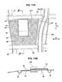
- FIG. 11A is an enlarged plan view of the No. 4 cross member and the panel area S10 according to the fourth embodiment of the present invention
- FIG. 11B is a sectional view taken along line XI-XI of FIG. 11A, illustrating the sectional structure of the No. 4 cross member and the panel area S10 in the longitudinal direction
- FIG. 12A is an enlarged plan view of the No. 4 cross member and the panel area S11 according to the fourth embodiment of the present invention
- FIG. 12B is a sectional view taken along line XII-XII of FIG. 12A, illustrating the sectional structure of the panel area S11 in the vehicle width direction WD.
- the substantially rectangular high-rigidity area 92 and the low-rigidity area 94 located at least partly around or near or in proximity of the high-rigidity area 92 within the panel area S10 as illustrated in FIG. 11A.
- the high-rigidity area 92 preferably is formed so as to project upward and its cross section is formed in the substantially trapezoid shape.
- the low-rigidity area 94 preferably is formed in the substantially flat shape, and the above-described asphalt-based damping material 96 is provided on at least part of is area, preferably its substantially entire area like the first and third embodiments.
- the high-rigidity area 92 includes three straight-extending sides and one side contacting the No. 4 cross member 29.
- This No. 4 cross member 29 is configured such that the vibration transmission from the side sill 20 is suppressed by the above-described rigidity reduction portion 110.
- the low-rigidity area 94 is formed with the specified (predetermined or predeterminable) width so as not to increase the rigidity of the low-rigidity area 94 improperly like the above-described first through third embodiments.
- the bracket 98 is at least partly disposed in the space which the upward-projecting high-rigidity area 92 creates, and the auxiliary component 100 is attached on the upper face of the high-rigidity area 92 via this bracket 98.
- the bracket 98 is coupled to the No. 4 cross member 29 at its one side.
- the high-rigidity area 92 with the auxiliary component 100 constitutes the heavy-weight area 92 like the above-described panel area S13 and S14.
- the (preferably substantially rectangular) high-rigidity area 92 with the slightly curved sides is formed within the panel area S11.
- the rear side and the inside side of the high-rigidity area 92 contact the middle portions of the No. 4 cross member 29 and the bent line portion 54, respectively.
- the low-rigidity area 94 extending in the L shape, which has the specified (predetermined or predeterminable) width so as not to increase its rigidity improperly, like the above-described first through third embodiments.
- the side sill 20 generates its torsional vibration around a longitudinal axis and/or its bending vibration in the vertical and/or lateral directions (or in a direction at an angle different from 0° or 180°, preferably substantially normal to the longitudinal direction)
- vibration with the torsion and/or the bending is transmitted to the No. 4 cross member 29.
- the rigidity reduction portion 110 has its lower rigidity in the vehicle width direction compared with the other portions of the No. 4 cross member 29 as described above, and accordingly it tends to be deformed easily by such vibration with the torsion or bending.
- FIGS. 13 A and 13B the function of the rigidity reduction portion 110 will be described more specifically referring to FIGS. 13 A and 13B.
- the side sills 20 As illustrated in FIG. 13A, where a force denoted by A in the figure is applied to the side sills 20 e.g. due to a pushing-up force of the suspension from the road surface or the like, the side sills 20 generate the bending vibration with vertically-curved deformation. Also, an entire upper body 122 of the vehicle body including the pillars 35 and a roof 120 generates the vibration with the torsional deformation (see FIG. 13B).
- the pillars 35 When the upper body 122 generate such vibration, the pillars 35 generates a vibration with a laterally-curved deformation as illustrated in FIG. 13B. This may be the same as a case where, for example, when a box with a closed cross section was twisted, the side face of the box would generate a bending deformation.
- the pillars 35 are connected to the side sills 20, the side sills 20 generate the vibration with the laterally-inclining deformation as illustrated by B in the drawing.
- the No. 4 cross member 29 generates a vibration with bending deformation as illustrated by a broken line C.
- the rigidity reduction portion 110 is formed at the No. 4 cross member 29 which is or is to be coupled to the side sills 20, the vibration can be prevented effectively from being transmitted to the No. 4 cross member inwardly where the side sills 20 would generate the torsional vibration with the laterally-inclining deformation due to the bending vibration of the pillars 35 caused by the torsional vibration of the upper body 122.
- the no rigidity reduction portion is provided at the other cross members, such as the No. 3 cross member 28, the sufficiently large rigidity of the vehicle body can be ensured.
- the side sills 20 generates the vibration with laterally-curved deformation when a side force is applied to the suspension from the road surface.
- This vibration causes the No. 4 cross member 13A to generate a vibration with the bending deformation as illustrated by E in FIG. 13A.
- This vibration causing the bending deformation is increased intensively at the rigidity reduction portion 110, and particularly the recess portion 112c and 112d formed at the front and rear faces 29c and 29d of the rigidity reduction portion 110 deform greatly. As a result, the vibration which will be transmitted from the rigidity reduction portion 110 inwardly is reduced.
- the function and effect of the damping material 116 provided at the rigidity reduction portion 110 will be described. Sine the damping material 116 is intensively disposed in the space with the substantially arc-shaped or bent cross section of the recess portions 112 in the present embodiment, the vibration intensively increased at the recess portions 112 can be decreased. As a result, the vibration can be prevented from being transmitted from the recess portions 112 inwardly.
- the width of the recess portions 112 of the example illustrated in FIGS. 10A, 10B is greater, the rigidity in the vehicle width direction can be smaller further. As a result, the great vibration can be prevented from being transmitted inwardly surely. Also, since the recess portions 112 of the modified example are formed contacting the side sills 20, the vibration with various deformations, such as bending and torsional deformations, can be increased intensively at the recess portions 112 more surely. Further, since the recess portions 112 preferably have the substantially V- or U-shaped cross section, its rigidity can be made further smaller.
- the vibration energy at the panel area can be reduced effectively by providing the rigidity reduction portion at the frame member and the like.
- providing the rigidity reduction portion at the frame member can reduce the vibration transmitted to the floor panels, without having any interference with objects, such as the exhaust pipe and auxiliary components, and with its appropriate height which can provide the passengers with comfortable stepping.
- the rigidity reduction portion 110 as the vibration transmission reduction structure, is provided at the frame member 29 to reduce the vibration transmitted to the panel area
- the high-rigidity area 92 and/or the low-rigidity area 94 as the preferred vibration reduction structure, are preferably provided within the panel area S10 and S11 to reduce the acoustic emission generated from the floor area S10 and S11.
- the rigidity of the respective high-rigidity area 92 can be increased greatly and thereby the rigidity difference between the high-rigidity area 92 and the low-rigidity area 94 can be further increased. Accordingly, even where the rigidity of the panel area itself is relatively high due to its relatively small area, the difference in rigidity between them can be ensured greatly. Thus, the vibration energy can be increased intensively at the low-rigidity area. Further, the increasing of the vibration energy at the low-rigidity area can be furthered at the panel area S10 by the increased difference in weight between the both area with the bracket 98 and the auxiliary component 100.
- the vibration transmission from the side sills is suppressed properly at the No. 4 cross member 29 the respective high-rigidity area 92 contact as described above, the great vibration can be prevented from being transmitted to the panel area S10 and S11.
- the acoustic emission caused by the vibration transmitted to the panel area S10 and S11 from the No. 4 cross member 29 can be reduced, and the vibration reduction effect can be obtained surely by increasing the rigidity of the high-rigidity area 92 properly. Accordingly, regardless of the above-described limitations in vehicle-body structure, such as height, locations, size and the like, or manufacturing, the vibration energy at the panel area can be reduced effectively by the increased rigidity of the heavy-weight area contacting the cross members.
Landscapes
- Engineering & Computer Science (AREA)
- Mechanical Engineering (AREA)
- Chemical & Material Sciences (AREA)
- Combustion & Propulsion (AREA)
- Transportation (AREA)
- Physics & Mathematics (AREA)
- Acoustics & Sound (AREA)
- Body Structure For Vehicles (AREA)
Applications Claiming Priority (2)
| Application Number | Priority Date | Filing Date | Title |
|---|---|---|---|
| JP2004185016A JP2006007862A (ja) | 2004-06-23 | 2004-06-23 | 車体のフロアパネル構造 |
| JP2004185016 | 2004-06-23 |
Publications (1)
| Publication Number | Publication Date |
|---|---|
| EP1609702A1 true EP1609702A1 (fr) | 2005-12-28 |
Family
ID=34937581
Family Applications (1)
| Application Number | Title | Priority Date | Filing Date |
|---|---|---|---|
| EP05013362A Withdrawn EP1609702A1 (fr) | 2004-06-23 | 2005-06-21 | Structure de panneau de plancher et carrosserie du véhicule ainsi équipée |
Country Status (3)
| Country | Link |
|---|---|
| US (1) | US7243984B2 (fr) |
| EP (1) | EP1609702A1 (fr) |
| JP (1) | JP2006007862A (fr) |
Cited By (4)
| Publication number | Priority date | Publication date | Assignee | Title |
|---|---|---|---|---|
| EP3300993A1 (fr) * | 2016-09-28 | 2018-04-04 | Toyota Jidosha Kabushiki Kaisha | Structure de vehicule |
| WO2020020615A1 (fr) * | 2018-07-27 | 2020-01-30 | Bayerische Motoren Werke Aktiengesellschaft | Carrosserie de véhicule avec point d'ajustage pour connecter une masse d'ajustage, et procédé pour ajuster les caractéristiques acoustiques d'un véhicule |
| EP3871952A1 (fr) * | 2020-02-26 | 2021-09-01 | Mazda Motor Corporation | Structure de carrosserie de véhicule et véhicule |
| US20230133645A1 (en) * | 2020-04-27 | 2023-05-04 | Bayerische Motoren Werke Aktiengesellschaft | Underbody Arrangement |
Families Citing this family (11)
| Publication number | Priority date | Publication date | Assignee | Title |
|---|---|---|---|---|
| US20060163914A1 (en) * | 2005-01-27 | 2006-07-27 | Mazda Motor Corporation | Floor panel structure for automobile body |
| US7625037B2 (en) * | 2005-09-20 | 2009-12-01 | Gm Global Technology Operations, Inc. | Vehicle body panel access feature |
| JP4302151B2 (ja) * | 2007-04-20 | 2009-07-22 | 本田技研工業株式会社 | 車両用フロアパネル |
| USD579843S1 (en) * | 2007-09-20 | 2008-11-04 | International Truck Intellectual Property Company, Llc | Chassis skirt system of a truck vehicle |
| US20120135194A1 (en) * | 2010-11-24 | 2012-05-31 | Honda Motor Co., Ltd. | High-viscosity material application device, high-viscosity material application method, and high-viscosity material coating |
| JP6341167B2 (ja) * | 2015-09-07 | 2018-06-13 | トヨタ自動車株式会社 | 車両振動抑制構造 |
| DE102016213262A1 (de) * | 2016-07-20 | 2018-01-25 | Bayerische Motoren Werke Aktiengesellschaft | Kraftfahrzeug |
| US10906592B2 (en) * | 2017-12-01 | 2021-02-02 | Mazda Motor Corporation | Vehicle body structure |
| JP6888534B2 (ja) | 2017-12-05 | 2021-06-16 | トヨタ自動車株式会社 | フロアパネルの構造 |
| DE102018208732A1 (de) * | 2018-06-04 | 2019-12-05 | Bayerische Motoren Werke Aktiengesellschaft | Karosseriebauteil mit Verschlusselement sowie Verfahren zum funktionsgerechten Verschließen einer Öffnung mit nicht nicht-formschlüssigem Verschlusselement in einem Karosseriebauteil |
| JP7593203B2 (ja) * | 2021-03-31 | 2024-12-03 | マツダ株式会社 | 振動減衰構造 |
Citations (5)
| Publication number | Priority date | Publication date | Assignee | Title |
|---|---|---|---|---|
| JPS58218472A (ja) * | 1982-06-11 | 1983-12-19 | Nissan Motor Co Ltd | 車体フロア構造 |
| DE3837231A1 (de) * | 1987-11-02 | 1989-05-18 | Honda Motor Co Ltd | Verfahren zur herstellung einer wand einer fahrzeugkarosserie mit einer waben-doppelschichtstruktur |
| DE3844145A1 (de) * | 1987-12-28 | 1989-07-13 | Honda Motor Co Ltd | Schichtstoffdaemmaterial fuer fahrzeuge |
| EP1281604A2 (fr) * | 2001-07-30 | 2003-02-05 | Mazda Motor Corporation | Structure de plancher de véhicule automobile |
| JP2003112092A (ja) * | 2001-10-02 | 2003-04-15 | Cemedine Henkel Co Ltd | 制振材付車体パネル及び制振材塗布装置並びに制振材施工方法 |
Family Cites Families (11)
| Publication number | Priority date | Publication date | Assignee | Title |
|---|---|---|---|---|
| US1624903A (en) * | 1923-12-05 | 1927-04-12 | American Motor Body Corp | Vehicle underbody construction |
| US2126607A (en) * | 1935-11-09 | 1938-08-09 | Gen Motors Corp | Metal underbody construction |
| US2856226A (en) * | 1955-01-19 | 1958-10-14 | Gen Motors Corp | Vehicle frame assembly |
| FR2053884A5 (fr) * | 1969-07-22 | 1971-04-16 | Peugeot & Renault | |
| JPS56120460A (en) * | 1980-02-27 | 1981-09-21 | Mazda Motor Corp | Body panel structure of automobile |
| US5540880A (en) * | 1987-08-12 | 1996-07-30 | Nagoya Oil Chemical Co., Ltd. | Corrosion, sound, and vibration-proof method for metal structure |
| JPH06107235A (ja) | 1992-09-29 | 1994-04-19 | Toyota Motor Corp | 車体パネル構造 |
| US5635562A (en) * | 1995-04-26 | 1997-06-03 | Lear Corporation | Expandable vibration damping materials |
| EP1439110A3 (fr) * | 2003-01-16 | 2004-11-03 | Mazda Motor Corporation | Structure de panneau de plancher pour véhicule |
| JP4019421B2 (ja) * | 2003-08-20 | 2007-12-12 | マツダ株式会社 | 自動車のフロアパネル構造 |
| JP2005067491A (ja) * | 2003-08-26 | 2005-03-17 | Honda Motor Co Ltd | 車体構造 |
-
2004
- 2004-06-23 JP JP2004185016A patent/JP2006007862A/ja active Pending
-
2005
- 2005-05-11 US US11/126,149 patent/US7243984B2/en not_active Expired - Fee Related
- 2005-06-21 EP EP05013362A patent/EP1609702A1/fr not_active Withdrawn
Patent Citations (5)
| Publication number | Priority date | Publication date | Assignee | Title |
|---|---|---|---|---|
| JPS58218472A (ja) * | 1982-06-11 | 1983-12-19 | Nissan Motor Co Ltd | 車体フロア構造 |
| DE3837231A1 (de) * | 1987-11-02 | 1989-05-18 | Honda Motor Co Ltd | Verfahren zur herstellung einer wand einer fahrzeugkarosserie mit einer waben-doppelschichtstruktur |
| DE3844145A1 (de) * | 1987-12-28 | 1989-07-13 | Honda Motor Co Ltd | Schichtstoffdaemmaterial fuer fahrzeuge |
| EP1281604A2 (fr) * | 2001-07-30 | 2003-02-05 | Mazda Motor Corporation | Structure de plancher de véhicule automobile |
| JP2003112092A (ja) * | 2001-10-02 | 2003-04-15 | Cemedine Henkel Co Ltd | 制振材付車体パネル及び制振材塗布装置並びに制振材施工方法 |
Non-Patent Citations (2)
| Title |
|---|
| PATENT ABSTRACTS OF JAPAN vol. 008, no. 073 (M - 287) 5 April 1984 (1984-04-05) * |
| PATENT ABSTRACTS OF JAPAN vol. 2003, no. 08 6 August 2003 (2003-08-06) * |
Cited By (6)
| Publication number | Priority date | Publication date | Assignee | Title |
|---|---|---|---|---|
| EP3300993A1 (fr) * | 2016-09-28 | 2018-04-04 | Toyota Jidosha Kabushiki Kaisha | Structure de vehicule |
| WO2020020615A1 (fr) * | 2018-07-27 | 2020-01-30 | Bayerische Motoren Werke Aktiengesellschaft | Carrosserie de véhicule avec point d'ajustage pour connecter une masse d'ajustage, et procédé pour ajuster les caractéristiques acoustiques d'un véhicule |
| EP3871952A1 (fr) * | 2020-02-26 | 2021-09-01 | Mazda Motor Corporation | Structure de carrosserie de véhicule et véhicule |
| CN113386865A (zh) * | 2020-02-26 | 2021-09-14 | 马自达汽车株式会社 | 车辆的车身结构 |
| US20230133645A1 (en) * | 2020-04-27 | 2023-05-04 | Bayerische Motoren Werke Aktiengesellschaft | Underbody Arrangement |
| US12454171B2 (en) * | 2020-04-27 | 2025-10-28 | Bayerische Motoren Werke Aktiengesellschaft | Underbody arrangement |
Also Published As
| Publication number | Publication date |
|---|---|
| US7243984B2 (en) | 2007-07-17 |
| JP2006007862A (ja) | 2006-01-12 |
| US20050285432A1 (en) | 2005-12-29 |
Similar Documents
| Publication | Publication Date | Title |
|---|---|---|
| US8708390B2 (en) | Vehicle-body structure of vehicle and manufacturing method of the same | |
| EP2033879B1 (fr) | Structure avant de véhicule | |
| JP5879938B2 (ja) | 車両後部の側部パネルの補強構造 | |
| US7243984B2 (en) | Floor panel structure of vehicle body | |
| JP7028017B2 (ja) | 車両の前部車体構造 | |
| JP2023015307A (ja) | 車両側部構造 | |
| JP7056303B2 (ja) | 車両の前部車体構造 | |
| JP7013995B2 (ja) | 車両の前部車体構造 | |
| EP1721809B1 (fr) | Structure de la partie arrière d'un véhicule automobile | |
| EP3632780B1 (fr) | Structure de carrosserie avant de véhicule et son procédé de formation | |
| JP7056302B2 (ja) | 車両の前部車体構造 | |
| JPH0930452A (ja) | 自動車用サイドシル補強構造 | |
| JP5478724B2 (ja) | 車体前部構造 | |
| CN109895869B (zh) | 车身的地板构造 | |
| US20050264041A1 (en) | Floor panel structure of vehicle body | |
| JP2001063620A (ja) | 自動車の車体構造 | |
| EP1721810A2 (fr) | Structure de carrosserie d'un véhicule automobile | |
| JP4518249B2 (ja) | 車体のフロアパネル構造 | |
| JP4395738B2 (ja) | 車体のフロアパネル構造 | |
| JP5496727B2 (ja) | 自動車の前部車体構造 | |
| CN115123395A (zh) | 车身侧部结构及车身侧部结构的制造方法 | |
| JP2002205665A (ja) | ホイールハウス部構造 | |
| JP2006007861A (ja) | 車体構造 | |
| JP2005001406A (ja) | 自動車の車体前部構造 | |
| JP2002370672A (ja) | 自動車の車体前部構造 |
Legal Events
| Date | Code | Title | Description |
|---|---|---|---|
| PUAI | Public reference made under article 153(3) epc to a published international application that has entered the european phase |
Free format text: ORIGINAL CODE: 0009012 |
|
| AK | Designated contracting states |
Kind code of ref document: A1 Designated state(s): AT BE BG CH CY CZ DE DK EE ES FI FR GB GR HU IE IS IT LI LT LU MC NL PL PT RO SE SI SK TR |
|
| AX | Request for extension of the european patent |
Extension state: AL BA HR LV MK YU |
|
| 17P | Request for examination filed |
Effective date: 20060427 |
|
| AKX | Designation fees paid |
Designated state(s): DE |
|
| 17Q | First examination report despatched |
Effective date: 20070125 |
|
| STAA | Information on the status of an ep patent application or granted ep patent |
Free format text: STATUS: THE APPLICATION IS DEEMED TO BE WITHDRAWN |
|
| 18D | Application deemed to be withdrawn |
Effective date: 20090217 |