EP1609717A1 - Befestigung, insbesondere zur Vertauung von Fahrzeugen an Bord von Schiffen, und Verfahren zur Anbringung einer solcher Befestigung am Deck - Google Patents
Befestigung, insbesondere zur Vertauung von Fahrzeugen an Bord von Schiffen, und Verfahren zur Anbringung einer solcher Befestigung am Deck Download PDFInfo
- Publication number
- EP1609717A1 EP1609717A1 EP04425454A EP04425454A EP1609717A1 EP 1609717 A1 EP1609717 A1 EP 1609717A1 EP 04425454 A EP04425454 A EP 04425454A EP 04425454 A EP04425454 A EP 04425454A EP 1609717 A1 EP1609717 A1 EP 1609717A1
- Authority
- EP
- European Patent Office
- Prior art keywords
- cup
- deck
- sealing
- housing seat
- welding
- Prior art date
- Legal status (The legal status is an assumption and is not a legal conclusion. Google has not performed a legal analysis and makes no representation as to the accuracy of the status listed.)
- Granted
Links
- 238000000034 method Methods 0.000 title claims description 29
- 238000003466 welding Methods 0.000 claims abstract description 44
- 238000007789 sealing Methods 0.000 claims abstract description 32
- 239000003566 sealing material Substances 0.000 claims abstract description 24
- 239000011324 bead Substances 0.000 claims abstract description 12
- 230000008595 infiltration Effects 0.000 claims abstract description 5
- 238000001764 infiltration Methods 0.000 claims abstract description 5
- 238000003780 insertion Methods 0.000 claims description 11
- 230000037431 insertion Effects 0.000 claims description 11
- 238000010276 construction Methods 0.000 claims description 10
- 230000008021 deposition Effects 0.000 claims description 7
- 238000009966 trimming Methods 0.000 claims description 7
- 238000009826 distribution Methods 0.000 claims description 6
- 239000000463 material Substances 0.000 claims description 3
- XLYOFNOQVPJJNP-UHFFFAOYSA-N water Substances O XLYOFNOQVPJJNP-UHFFFAOYSA-N 0.000 claims description 3
- 230000009471 action Effects 0.000 claims description 2
- 229920001296 polysiloxane Polymers 0.000 claims description 2
- 101100327917 Caenorhabditis elegans chup-1 gene Proteins 0.000 abstract description 41
- 239000011241 protective layer Substances 0.000 description 10
- 239000010410 layer Substances 0.000 description 4
- 230000014759 maintenance of location Effects 0.000 description 4
- 230000008901 benefit Effects 0.000 description 3
- 239000003973 paint Substances 0.000 description 2
- 230000009467 reduction Effects 0.000 description 2
- 229920005989 resin Polymers 0.000 description 2
- 239000011347 resin Substances 0.000 description 2
- 239000011247 coating layer Substances 0.000 description 1
- 230000007797 corrosion Effects 0.000 description 1
- 238000005260 corrosion Methods 0.000 description 1
- 230000007423 decrease Effects 0.000 description 1
- 230000001934 delay Effects 0.000 description 1
- 230000006866 deterioration Effects 0.000 description 1
- 239000003822 epoxy resin Substances 0.000 description 1
- 239000000945 filler Substances 0.000 description 1
- LNEPOXFFQSENCJ-UHFFFAOYSA-N haloperidol Chemical compound C1CC(O)(C=2C=CC(Cl)=CC=2)CCN1CCCC(=O)C1=CC=C(F)C=C1 LNEPOXFFQSENCJ-UHFFFAOYSA-N 0.000 description 1
- 238000005304 joining Methods 0.000 description 1
- 239000007788 liquid Substances 0.000 description 1
- 238000004519 manufacturing process Methods 0.000 description 1
- 238000005457 optimization Methods 0.000 description 1
- 230000008520 organization Effects 0.000 description 1
- 230000035515 penetration Effects 0.000 description 1
- 230000002093 peripheral effect Effects 0.000 description 1
- 229920000647 polyepoxide Polymers 0.000 description 1
- 238000002360 preparation method Methods 0.000 description 1
- 230000001681 protective effect Effects 0.000 description 1
- 230000003014 reinforcing effect Effects 0.000 description 1
- 239000013535 sea water Substances 0.000 description 1
- 238000003892 spreading Methods 0.000 description 1
- 230000007480 spreading Effects 0.000 description 1
- 230000003068 static effect Effects 0.000 description 1
- 238000004381 surface treatment Methods 0.000 description 1
Images


Classifications
-
- B—PERFORMING OPERATIONS; TRANSPORTING
- B63—SHIPS OR OTHER WATERBORNE VESSELS; RELATED EQUIPMENT
- B63B—SHIPS OR OTHER WATERBORNE VESSELS; EQUIPMENT FOR SHIPPING
- B63B25/00—Load-accommodating arrangements, e.g. stowing, trimming; Vessels characterised thereby
- B63B25/24—Means for preventing unwanted cargo movement, e.g. dunnage
-
- B—PERFORMING OPERATIONS; TRANSPORTING
- B60—VEHICLES IN GENERAL
- B60P—VEHICLES ADAPTED FOR LOAD TRANSPORTATION OR TO TRANSPORT, TO CARRY, OR TO COMPRISE SPECIAL LOADS OR OBJECTS
- B60P7/00—Securing or covering of load on vehicles
- B60P7/06—Securing of load
- B60P7/08—Securing to the vehicle floor or sides
- B60P7/0807—Attachment points
-
- B—PERFORMING OPERATIONS; TRANSPORTING
- B63—SHIPS OR OTHER WATERBORNE VESSELS; RELATED EQUIPMENT
- B63B—SHIPS OR OTHER WATERBORNE VESSELS; EQUIPMENT FOR SHIPPING
- B63B25/00—Load-accommodating arrangements, e.g. stowing, trimming; Vessels characterised thereby
-
- B—PERFORMING OPERATIONS; TRANSPORTING
- B63—SHIPS OR OTHER WATERBORNE VESSELS; RELATED EQUIPMENT
- B63B—SHIPS OR OTHER WATERBORNE VESSELS; EQUIPMENT FOR SHIPPING
- B63B25/00—Load-accommodating arrangements, e.g. stowing, trimming; Vessels characterised thereby
- B63B25/002—Load-accommodating arrangements, e.g. stowing, trimming; Vessels characterised thereby for goods other than bulk goods
- B63B25/008—Load-accommodating arrangements, e.g. stowing, trimming; Vessels characterised thereby for goods other than bulk goods for wheeled cargo
-
- B—PERFORMING OPERATIONS; TRANSPORTING
- B63—SHIPS OR OTHER WATERBORNE VESSELS; RELATED EQUIPMENT
- B63B—SHIPS OR OTHER WATERBORNE VESSELS; EQUIPMENT FOR SHIPPING
- B63B25/00—Load-accommodating arrangements, e.g. stowing, trimming; Vessels characterised thereby
- B63B25/28—Load-accommodating arrangements, e.g. stowing, trimming; Vessels characterised thereby for deck loads
-
- B—PERFORMING OPERATIONS; TRANSPORTING
- B63—SHIPS OR OTHER WATERBORNE VESSELS; RELATED EQUIPMENT
- B63B—SHIPS OR OTHER WATERBORNE VESSELS; EQUIPMENT FOR SHIPPING
- B63B25/00—Load-accommodating arrangements, e.g. stowing, trimming; Vessels characterised thereby
- B63B25/24—Means for preventing unwanted cargo movement, e.g. dunnage
- B63B2025/245—Means for preventing unwanted cargo movement, e.g. dunnage of wheeled cargo, e.g. vehicle retainers
Definitions
- the present invention relates to a cup, in particular for lashing down vehicles on-board ships, and to a method for assembling said cup on the deck of a ship.
- the cups forming the subject of the present invention may be advantageously assembled on loading decks and on vehicle decks of cargo ships, ferries or vessels of various types for lashing down containers, pallets or vehicles.
- the loading decks are provided with lashing cups or deck sockets suitable for securing lashes or other ties used in order to immobilise the loads.
- These cups are distributed uniformly in a large number over the whole useful surface area of the loading decks so as to ensure fixing of the load in the most suitable position depending on the stability, space and distribution requirements mentioned above.
- the abovementioned housing seats consist of through-openings which, generally but not necessarily, have a circular shape and are formed directly on the structure of the deck with diameters in the region of 30 cm.
- the cups must have mechanical strength properties similar to those of the remaining part of the deck since they must be able to withstand the rated load values envisaged for the said decks, such as, for example, the concentrated load due to the wheel of a heavy motor vehicle.
- FIG. A and B An example of a lashing cup of the traditional type is shown in Figures A and B.
- the cup which is indicated in each case by C, essentially consists of a shaped hollowed body formed by an upper plate D, which is intended to be welded in a coplanar manner to the walking surface F, and by a bowl-shaped element E which is welded peripherally underneath the said plate D.
- An incision T is formed on the plate D, which incision may for example be cross-shaped as in the example shown in the figures and is intended to receive an engaging element Y of a lash for retaining the load.
- the bowl-shaped element E essentially has the function of closing the incision T, leaving the space necessary for insertion of the engaging element, so as to prevent rain water or anything else which might pass through the incision T from falling onto the underlying deck.
- assembly of the abovementioned cup on the deck structure involves two separate operating steps which are performed during different stages of construction of the ship essentially for practical reasons relating to organization of the work.
- a retaining step is performed in order to fix provisionally the cup inside the housing seat. Retention of the cup is achieved by means of spot welds performed along the perimeter of the cup on the side opposite to the walking side. This step is performed during the preliminary stage of construction of the load-bearing structure of the ship, when the decks are upturned with respect to their final position and for this reason are easily accessible on the side opposite to the walking side. In this way the welding personnel is able to operate on this deck side without the need to use scaffolding or perform overhead welds.
- a strength-welding step which is intended to fasten the cup rigidly to the deck so as to ensure the required structural strength thereof.
- a bead of weld is deposited on the walking side along the perimeter of the cup. This step is always performed when the decks of the ship have their walking surface directed upwards, during an advanced stage of construction of the load-bearing structure of the ship.
- FIG. B shows a cross-sectional view of the cup according to Figure A along the line B-B
- the spot welds performed during the retaining step are indicated by S1
- the strength-welding bead is indicated by S2.
- the plate D has a diameter which is smaller than the diameter of the housing seat so that, once the cup is fixed, a groove is defined for receiving the strength-welding bead between the plate D and the edge of the housing seat.
- the plate D of the cup is delimited along whole of its external perimeter by an inclined surface which helps define the groove with dimensions suitable for receiving a bead of weld able to satisfy the necessary structural requirements.
- the angle of inclination ⁇ of this inclined surface must in any case be equal to or greater than 45°.
- a drawback which frequently occurs during assembly of the cups is the damage to the protective layer of paint or resin present on the deck surface opposite to the walking side. This damage is caused by the high temperatures which are generated in the zones close to the cup housing seat during the strength-welding step.
- the damage is of relative importance since the walls of this area are easily accessible and do not require special anti-corrosive treatment.
- the protective layer may therefore be easily repaired without particular difficulty.
- the damage is more important when the damaged surface forms part of a ballast chamber.
- the protective layer is in perfect condition since the walls of this chamber are in direct contact with the sea water and must therefore be particularly corrosion-resistant.
- the products used for the coating layers may be easily damaged by heat and often are destroyed irreparably after the strength-welding operations. Owing to the particular working procedures required by the use of these products, the renewal of these protective layers is a very delicate and laborious operation and is also hindered by the fact that usually the environments in which the operating personnel have to work are particularly restricted and difficult to access once the construction of the load-bearing structure of the ship has been completed.
- the object of the present invention is to eliminate the drawbacks of the prior art mentioned above, by providing a lashing cup which may be welded to the deck of a ship without damaging the underlying protective layer.
- a further object of the present invention is that of providing a lashing cup which is constructionally simple and operationally entirely reliable.
- a further object of the present invention is that of providing a method for assembling these cups, which allows simplification of the operating steps.
- a further object of the present invention is that of providing a method for assembling these cups, which allows a reduction in the costs and time required for assembly on the decks.
- 1 denotes overall a preferred embodiment of a lashing cup according to the present invention.
- cup described below is intended for lashing down vehicles or trailers
- cup according to the present invention may obviously be advantageously used also for lashing down containers, pallets and loads in general, without thereby departing from the scope of the present patent.
- the lashing cup 1 according to the invention is intended to be inset in a housing seat formed in the thickness of a ship's deck and then fixed there by means of welding. Further fixing or reinforcing means, such as bolts or pins, may be envisaged, said elements being inserted so as to provide a connection between the deck and the cup 1 both on the walking surface and on the opposite side.
- the perimetral wall P extending through the whole thickness of the deck, is delimited between the walking surface F of the deck and the surface opposite it F1.
- the perimetral surface P may be at right angles to the walking surface F or may also be inclined with respect to the said surface depending on the shape of the cup 1 which is to be seated.
- the cup 1 is essentially a hollow body formed by a sheet-like element 2 and a bowl-shaped element 3.
- the sheet-like element 3 forms the upper portion of the cup and is positioned so as to close the housing seat Q continuously with the remaining walking surface F of the deck.
- the sheet-like element 3 is provided with a through-opening 20 suitably shaped so as to allow securing of an engaging element and is delimited in its thickness by a side surface 1 intended to interface with the perimetral wall P of the housing seat.
- the sheet-like element may also have concave or convex portions. Operationally it transmits onto the deck structure all the mechanical stresses received from the ties used for fixing the load.
- the sheet-like element 2 has a circular shape in order to facilitate insertion of the cup 1 inside the housing seat Q and extends substantially in a single plane which is parallel to the walking surface F when the cup 1 is assembled on the deck.
- the through-opening 20, which is formed in its centre, is cross-shaped.
- the sheet-like element 3 may be shaped with geometrical forms different from a circular shape, and likewise the said through-opening 20 may also have a different shape.
- the bowl-shaped element 3 forms the bottom portion of the cup 1 and is provided with a fixing edge 30 along which it is welded to the sheet-like element 2, on the opposite side to the walking side.
- the weld S3 for fixing the bowl-shaped element 3 onto the sheet-like element 2 is performed directly during manufacture and therefore need not be performed at the time of assembly of the cup 1 on the deck.
- the bowl-shaped element 3 allows closing of the through-opening 20 so as to prevent objects, liquids or the like from falling onto the underlying deck.
- the bowl-shaped element 3 is fixed to the sheet-like element 2 so that the perimeter of the said bowl-shaped element 3 completely encloses inside it the through-opening 20.
- the walls of the bowl-shaped element 3 and the sheet-like element 2 define an empty volume V inside the cup 1.
- This volume V essentially has the function of ensuring sufficient manoeuvring space for inserting into the through-opening 20 an engaging element of a lash (not shown in the figures since it is of the type known per se).
- the volume V may be obtained with the aid of rounding of the sheet-like element 2 which enables the concavity of the bowl-shaped element 3 to be reduced to the point of envisaging that the latter may also be replaced by a substantially flat sheet.
- the side surface 21 of the sheet-like element 2 has a discontinuity, and in particular comprises:
- the contact surface 22 is situated between the sealing surface 23 and the welding surface 24 so that the sealing surface 23 and the welding surface 24 are arranged in the vicinity, respectively, of the perimetral wall P and of the surface of the deck F1 opposite to the walking surface F, for effecting sealing and welding of the cup 1 to the deck.
- the sheet-like element 2 is formed by a main body 25 with a circular cross-section, in the centre of which a cross-shaped through-opening 20 is formed, and by a circular projecting edge 26 with a thickness h 1 , which extends from the side surface 21 concentrically with the abovementioned main body 25, its surface opposite to the walking surface being continuous.
- the main body 25 has a height h which is greater than the thickness h 1 of the projecting edge 26 and extends along its height h with a frustoconical portion 28 defined laterally by an inclined surface which forms the sealing surface 23 of the cup 1 and at the top by the walking surface 28b of the cup 1.
- the projecting edge 26 is in turn defined at the top by a surface in the form of a circular rim which forms the contact surface 22 of the cup 1 and laterally by a peripheral surface which forms the welding surface 24 of the cup 1.
- the side surface 21 of the cup 1 as defined above has a step-shaped profile which is intended to engage in a force-fitting manner with the perimetral wall P of the housing seat Q.
- the frustoconical portion 28 of the main body 25 may be easily inserted inside the housing seat, having a diameter which is on average smaller than that of the housing seat Q.
- the projecting edge 26, which has instead a larger diameter, allows the cup 1 to abut firmly against the deck structure in the region of the contact surface 22.
- the frustoconical portion 28 is formed with a height h 3 equivalent to the thickness of the deck, which is indicated by h 2 in Figures 1 and 2.
- the frustoconical portion 28 has, in the region of its wide base situated at the start of the projecting edge 26, a diameter which is equivalent to that of the housing seat. The diameter decreases in the direction away from the projecting edge 26, following the angle of inclination ⁇ of the sealing surface 23.
- a preferred value for the angle of inclination ⁇ of the sealing surface 23 is 95°.
- the contact surface 22 of the projecting edge 26 and the walking surface 28b of the cup 1 lie in two planes which are substantially parallel to each other so that the same contact surface 22 is coplanar with the walking surface F of the deck.
- the assembly method essentially comprises the following operating steps:
- the abovementioned strength-welding step is the sole welding step envisaged in this assembly method.
- this assembly method envisages that the sealing step is performed as two separate steps, namely:
- this sealing material does not possess mechanical strength characteristics.
- this sealing material is an organic-based synthetic product, preferably a rubber of the silicone type.
- the deposition step of a layer of sealing material is the first step in the assembly method.
- the sealing material is deposited preferably on the sealing surface 23 of the cup 1, forming a layer of uniform thickness.
- the sealing material may be deposited on the perimetral wall P of the housing seat Q or on both the surfaces at the same time, although in this latter case the thickness of the two layers must be reduced so as to avoid having excess material when the cup is fitted inside the housing seat.
- the deposition step is followed by the insertion step of the cup inside the housing seat Q.
- the cup 1 must be forced inside the seat Q until the contact surface 22 adheres to the deck surface F1 opposite the walking surface F. So that the cup 1 abuts firmly against the deck structure it is necessary to overcome the friction resulting from interference between the perimetral wall P of the seat Q and the base of the frustoconical portion 28 of the main body 25 of the cup 1, which will therefore have a diameter with calibrated dimensions.
- the abovementioned distribution step of the sealing material between the sealing surface 23 and the perimetral wall P is performed at the same time as the insertion step.
- insertion of the cup 1 inside the housing seat Q produces a compressive action which pushes the sealing material so that it occupies the whole of the cavity 29.
- the sealing material is thus able to adhere to the sealing surface 23 and to the perimetral wall P of the housing seat, forming a sealing filling. Any excess sealing material emerges from the cavity 29 along the walking surface F of the deck.
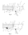
- a bead of weld is deposited so as to connect together the deck surface F1 opposite the walking surface and the welding surface 24.
- the bead must be of a size such as to ensure that the cup 1 has an adequate mechanical strength with respect to the stresses resulting from both the load fixing lashes and any static loads which are concentrated on the said cup 1.
- Figure 4 it is possible to appreciate the arrangement of the abovementioned sealing filler, which is indicated by the letter U, and the abovementioned strength-welding bead, indicated by the letter Z, with respect to the cup 1 and the deck structure.
- the operating steps described hitherto are all performed during a stage of construction of the ship where the decks are upturned and the surfaces of the decks opposite to the walking surfaces are directly accessible without the use of scaffolding. These steps are all performed before the traditional anti-corrosive surface treatment operations.
- the assembly method according to the invention also comprises a trimming step of the sealing material during which the excess sealing material emerging from the cavity 29 is eliminated by means of trimming performed along the walking surface F.
- This trimming step takes place after the strength-welding step and is performed, as the last step of the assembly method, during a stage of construction of the ship where the decks have the walking surface F directed upwards and the said walking surface F of the decks is directly accessible.
- the lashing cup according to the invention and the associated assembly method therefore allow a considerable reduction in the operating costs, in terms of both labour and materials used, while maintaining the same level of quality which can be achieved with conventional cups and methods.
- Another important advantage of the present invention consists in the fact that the costs of repairing the anti-corrosive protective layer on the side of the deck F1 opposite to the walking side are completely eliminated.
- strength-welding of the cup is performed before - and not after - spreading of the protective layer, as is instead envisaged in assembly methods of the conventional type.
Landscapes
- Engineering & Computer Science (AREA)
- Mechanical Engineering (AREA)
- Chemical & Material Sciences (AREA)
- Combustion & Propulsion (AREA)
- Ocean & Marine Engineering (AREA)
- Transportation (AREA)
- Lining Or Joining Of Plastics Or The Like (AREA)
- Seats For Vehicles (AREA)
- Connection Of Plates (AREA)
Priority Applications (3)
| Application Number | Priority Date | Filing Date | Title |
|---|---|---|---|
| EP04425454A EP1609717B1 (de) | 2004-06-22 | 2004-06-22 | Befestigung, insbesondere zur Vertauung von Fahrzeugen an Bord von Schiffen, und Verfahren zur Anbringung einer solcher Befestigung am Deck |
| DE602004020328T DE602004020328D1 (de) | 2004-06-22 | 2004-06-22 | Befestigung, insbesondere zur Vertauung von Fahrzeugen an Bord von Schiffen, und Verfahren zur Anbringung einer solcher Befestigung am Deck |
| AT04425454T ATE427261T1 (de) | 2004-06-22 | 2004-06-22 | Befestigung, insbesondere zur vertauung von fahrzeugen an bord von schiffen, und verfahren zur anbringung einer solcher befestigung am deck |
Applications Claiming Priority (1)
| Application Number | Priority Date | Filing Date | Title |
|---|---|---|---|
| EP04425454A EP1609717B1 (de) | 2004-06-22 | 2004-06-22 | Befestigung, insbesondere zur Vertauung von Fahrzeugen an Bord von Schiffen, und Verfahren zur Anbringung einer solcher Befestigung am Deck |
Publications (2)
| Publication Number | Publication Date |
|---|---|
| EP1609717A1 true EP1609717A1 (de) | 2005-12-28 |
| EP1609717B1 EP1609717B1 (de) | 2009-04-01 |
Family
ID=34932574
Family Applications (1)
| Application Number | Title | Priority Date | Filing Date |
|---|---|---|---|
| EP04425454A Expired - Lifetime EP1609717B1 (de) | 2004-06-22 | 2004-06-22 | Befestigung, insbesondere zur Vertauung von Fahrzeugen an Bord von Schiffen, und Verfahren zur Anbringung einer solcher Befestigung am Deck |
Country Status (3)
| Country | Link |
|---|---|
| EP (1) | EP1609717B1 (de) |
| AT (1) | ATE427261T1 (de) |
| DE (1) | DE602004020328D1 (de) |
Cited By (6)
| Publication number | Priority date | Publication date | Assignee | Title |
|---|---|---|---|---|
| WO2011019734A1 (en) * | 2009-08-13 | 2011-02-17 | Alcoa Inc. | Tie down assembly |
| WO2011090430A1 (en) * | 2010-01-22 | 2011-07-28 | Cargotec Sweden Ab | Anchor point |
| US8197166B2 (en) | 2009-05-14 | 2012-06-12 | Alcoa Inc. | Tie down assembly |
| US8505868B2 (en) | 2010-01-20 | 2013-08-13 | Alcoa Inc. | Tie down assembly |
| WO2013164039A1 (de) * | 2012-05-04 | 2013-11-07 | Olb Offshore Logistics Bremerhaven Gmbh | Ponton für den transport grosser und schwerer lasten |
| CN110696968A (zh) * | 2019-09-20 | 2020-01-17 | 江苏省船舶设计研究所有限公司 | 一种电力推进长江客渡船的甲板结构 |
Citations (2)
| Publication number | Priority date | Publication date | Assignee | Title |
|---|---|---|---|---|
| US3381925A (en) * | 1966-09-02 | 1968-05-07 | Davis Aircraft Products Inc | Tiedown fitting for ship decks |
| US4457650A (en) | 1982-01-04 | 1984-07-03 | Tseng Tsiung Siung | Reversible watertight type container securing assembly |
-
2004
- 2004-06-22 EP EP04425454A patent/EP1609717B1/de not_active Expired - Lifetime
- 2004-06-22 DE DE602004020328T patent/DE602004020328D1/de not_active Expired - Fee Related
- 2004-06-22 AT AT04425454T patent/ATE427261T1/de not_active IP Right Cessation
Patent Citations (2)
| Publication number | Priority date | Publication date | Assignee | Title |
|---|---|---|---|---|
| US3381925A (en) * | 1966-09-02 | 1968-05-07 | Davis Aircraft Products Inc | Tiedown fitting for ship decks |
| US4457650A (en) | 1982-01-04 | 1984-07-03 | Tseng Tsiung Siung | Reversible watertight type container securing assembly |
Cited By (10)
| Publication number | Priority date | Publication date | Assignee | Title |
|---|---|---|---|---|
| US8197166B2 (en) | 2009-05-14 | 2012-06-12 | Alcoa Inc. | Tie down assembly |
| WO2011019734A1 (en) * | 2009-08-13 | 2011-02-17 | Alcoa Inc. | Tie down assembly |
| US8360385B2 (en) | 2009-08-13 | 2013-01-29 | Alcoa Inc. | Tie down assembly |
| US8505868B2 (en) | 2010-01-20 | 2013-08-13 | Alcoa Inc. | Tie down assembly |
| WO2011090430A1 (en) * | 2010-01-22 | 2011-07-28 | Cargotec Sweden Ab | Anchor point |
| CN102712349A (zh) * | 2010-01-22 | 2012-10-03 | 货运技术瑞典股份公司 | 锚定点 |
| JP2013517978A (ja) * | 2010-01-22 | 2013-05-20 | カーゴテック・スウェーデン・アクチエボラ | アンカーポイント |
| CN102712349B (zh) * | 2010-01-22 | 2015-05-20 | 货运技术瑞典股份公司 | 锚定点 |
| WO2013164039A1 (de) * | 2012-05-04 | 2013-11-07 | Olb Offshore Logistics Bremerhaven Gmbh | Ponton für den transport grosser und schwerer lasten |
| CN110696968A (zh) * | 2019-09-20 | 2020-01-17 | 江苏省船舶设计研究所有限公司 | 一种电力推进长江客渡船的甲板结构 |
Also Published As
| Publication number | Publication date |
|---|---|
| DE602004020328D1 (de) | 2009-05-14 |
| ATE427261T1 (de) | 2009-04-15 |
| EP1609717B1 (de) | 2009-04-01 |
Similar Documents
| Publication | Publication Date | Title |
|---|---|---|
| EP1609717B1 (de) | Befestigung, insbesondere zur Vertauung von Fahrzeugen an Bord von Schiffen, und Verfahren zur Anbringung einer solcher Befestigung am Deck | |
| US7918255B2 (en) | Run flat device for a motor vehicle, and a wheel assembly incorporating it | |
| US8360385B2 (en) | Tie down assembly | |
| FI84246C (fi) | Fordonsflak. | |
| EP0061085B1 (de) | Anordnung zur Befestigung von Ladung | |
| JP2003502212A (ja) | タイヤ、リムおよびアダプタからなる組立体 | |
| US5733016A (en) | Wheel rim balance weight mounting | |
| US5284098A (en) | Air cargo pallet | |
| CZ293903B6 (cs) | Kolo vozidla s podpěrným tělesem nouzového chodu | |
| EP2526015B1 (de) | Ankerpunkt | |
| AU2010248095B2 (en) | Tie down assembly | |
| US20110031257A1 (en) | Pressure Container for a Transport Container Arrangement | |
| RU2757430C2 (ru) | Лоток для хранения, приспособленный для установки на конструкции кузова автомобиля | |
| US20030189084A1 (en) | Method of forming a stress isolating joint on a dump body | |
| US4111146A (en) | Tank support joint | |
| US20130068154A1 (en) | Boat or Ship Body of Aluminum-Based Material | |
| WO2025151251A1 (en) | Dump body with faceted shape | |
| EP2568085B1 (de) | Verfahren zum Transport von Baumaschinen in einem verschlossenen Container in einem Schiff | |
| US11964615B2 (en) | Fastening device for a container of a motor vehicle | |
| US20070228050A1 (en) | Fuel tank structure | |
| JP2003320988A (ja) | 船舶甲板上のハッチカバー構造体およびその製造方法 | |
| US20210069823A1 (en) | Friction-Stir-Welded Sheet-and-Post Sidewall | |
| KR20180039486A (ko) | 헬리데크의 리프팅 방법 | |
| FR3161421A1 (fr) | Conteneur economique | |
| US10352017B1 (en) | Manhole cover assembly |
Legal Events
| Date | Code | Title | Description |
|---|---|---|---|
| PUAI | Public reference made under article 153(3) epc to a published international application that has entered the european phase |
Free format text: ORIGINAL CODE: 0009012 |
|
| AK | Designated contracting states |
Kind code of ref document: A1 Designated state(s): AT BE BG CH CY CZ DE DK EE ES FI FR GB GR HU IE IT LI LU MC NL PL PT RO SE SI SK TR |
|
| AX | Request for extension of the european patent |
Extension state: AL HR LT LV MK |
|
| 17P | Request for examination filed |
Effective date: 20060404 |
|
| AKX | Designation fees paid |
Designated state(s): AT BE BG CH CY CZ DE DK EE ES FI FR GB GR HU IE IT LI LU MC NL PL PT RO SE SI SK TR |
|
| AXX | Extension fees paid |
Extension state: HR Payment date: 20060404 |
|
| GRAP | Despatch of communication of intention to grant a patent |
Free format text: ORIGINAL CODE: EPIDOSNIGR1 |
|
| GRAS | Grant fee paid |
Free format text: ORIGINAL CODE: EPIDOSNIGR3 |
|
| GRAA | (expected) grant |
Free format text: ORIGINAL CODE: 0009210 |
|
| AK | Designated contracting states |
Kind code of ref document: B1 Designated state(s): AT BE BG CH CY CZ DE DK EE ES FI FR GB GR HU IE IT LI LU MC NL PL PT RO SE SI SK TR |
|
| AX | Request for extension of the european patent |
Extension state: HR |
|
| REG | Reference to a national code |
Ref country code: GB Ref legal event code: FG4D |
|
| REG | Reference to a national code |
Ref country code: CH Ref legal event code: EP |
|
| REG | Reference to a national code |
Ref country code: IE Ref legal event code: FG4D |
|
| REF | Corresponds to: |
Ref document number: 602004020328 Country of ref document: DE Date of ref document: 20090514 Kind code of ref document: P |
|
| PG25 | Lapsed in a contracting state [announced via postgrant information from national office to epo] |
Ref country code: SI Free format text: LAPSE BECAUSE OF FAILURE TO SUBMIT A TRANSLATION OF THE DESCRIPTION OR TO PAY THE FEE WITHIN THE PRESCRIBED TIME-LIMIT Effective date: 20090401 |
|
| NLV1 | Nl: lapsed or annulled due to failure to fulfill the requirements of art. 29p and 29m of the patents act | ||
| PG25 | Lapsed in a contracting state [announced via postgrant information from national office to epo] |
Ref country code: PT Free format text: LAPSE BECAUSE OF FAILURE TO SUBMIT A TRANSLATION OF THE DESCRIPTION OR TO PAY THE FEE WITHIN THE PRESCRIBED TIME-LIMIT Effective date: 20090902 Ref country code: EE Free format text: LAPSE BECAUSE OF FAILURE TO SUBMIT A TRANSLATION OF THE DESCRIPTION OR TO PAY THE FEE WITHIN THE PRESCRIBED TIME-LIMIT Effective date: 20090401 Ref country code: AT Free format text: LAPSE BECAUSE OF FAILURE TO SUBMIT A TRANSLATION OF THE DESCRIPTION OR TO PAY THE FEE WITHIN THE PRESCRIBED TIME-LIMIT Effective date: 20090401 Ref country code: ES Free format text: LAPSE BECAUSE OF FAILURE TO SUBMIT A TRANSLATION OF THE DESCRIPTION OR TO PAY THE FEE WITHIN THE PRESCRIBED TIME-LIMIT Effective date: 20090712 Ref country code: FI Free format text: LAPSE BECAUSE OF FAILURE TO SUBMIT A TRANSLATION OF THE DESCRIPTION OR TO PAY THE FEE WITHIN THE PRESCRIBED TIME-LIMIT Effective date: 20090401 |
|
| PG25 | Lapsed in a contracting state [announced via postgrant information from national office to epo] |
Ref country code: SE Free format text: LAPSE BECAUSE OF FAILURE TO SUBMIT A TRANSLATION OF THE DESCRIPTION OR TO PAY THE FEE WITHIN THE PRESCRIBED TIME-LIMIT Effective date: 20090701 Ref country code: PL Free format text: LAPSE BECAUSE OF FAILURE TO SUBMIT A TRANSLATION OF THE DESCRIPTION OR TO PAY THE FEE WITHIN THE PRESCRIBED TIME-LIMIT Effective date: 20090401 Ref country code: NL Free format text: LAPSE BECAUSE OF FAILURE TO SUBMIT A TRANSLATION OF THE DESCRIPTION OR TO PAY THE FEE WITHIN THE PRESCRIBED TIME-LIMIT Effective date: 20090401 |
|
| PG25 | Lapsed in a contracting state [announced via postgrant information from national office to epo] |
Ref country code: MC Free format text: LAPSE BECAUSE OF NON-PAYMENT OF DUE FEES Effective date: 20090630 Ref country code: CZ Free format text: LAPSE BECAUSE OF FAILURE TO SUBMIT A TRANSLATION OF THE DESCRIPTION OR TO PAY THE FEE WITHIN THE PRESCRIBED TIME-LIMIT Effective date: 20090401 Ref country code: RO Free format text: LAPSE BECAUSE OF FAILURE TO SUBMIT A TRANSLATION OF THE DESCRIPTION OR TO PAY THE FEE WITHIN THE PRESCRIBED TIME-LIMIT Effective date: 20090401 Ref country code: DK Free format text: LAPSE BECAUSE OF FAILURE TO SUBMIT A TRANSLATION OF THE DESCRIPTION OR TO PAY THE FEE WITHIN THE PRESCRIBED TIME-LIMIT Effective date: 20090401 |
|
| REG | Reference to a national code |
Ref country code: CH Ref legal event code: PL |
|
| PLBE | No opposition filed within time limit |
Free format text: ORIGINAL CODE: 0009261 |
|
| STAA | Information on the status of an ep patent application or granted ep patent |
Free format text: STATUS: NO OPPOSITION FILED WITHIN TIME LIMIT |
|
| PG25 | Lapsed in a contracting state [announced via postgrant information from national office to epo] |
Ref country code: BE Free format text: LAPSE BECAUSE OF FAILURE TO SUBMIT A TRANSLATION OF THE DESCRIPTION OR TO PAY THE FEE WITHIN THE PRESCRIBED TIME-LIMIT Effective date: 20090401 Ref country code: SK Free format text: LAPSE BECAUSE OF FAILURE TO SUBMIT A TRANSLATION OF THE DESCRIPTION OR TO PAY THE FEE WITHIN THE PRESCRIBED TIME-LIMIT Effective date: 20090401 |
|
| 26N | No opposition filed |
Effective date: 20100105 |
|
| GBPC | Gb: european patent ceased through non-payment of renewal fee |
Effective date: 20090701 |
|
| REG | Reference to a national code |
Ref country code: FR Ref legal event code: ST Effective date: 20100226 |
|
| PG25 | Lapsed in a contracting state [announced via postgrant information from national office to epo] |
Ref country code: BG Free format text: LAPSE BECAUSE OF FAILURE TO SUBMIT A TRANSLATION OF THE DESCRIPTION OR TO PAY THE FEE WITHIN THE PRESCRIBED TIME-LIMIT Effective date: 20090701 |
|
| REG | Reference to a national code |
Ref country code: IE Ref legal event code: MM4A |
|
| PG25 | Lapsed in a contracting state [announced via postgrant information from national office to epo] |
Ref country code: IE Free format text: LAPSE BECAUSE OF NON-PAYMENT OF DUE FEES Effective date: 20090622 Ref country code: FR Free format text: LAPSE BECAUSE OF NON-PAYMENT OF DUE FEES Effective date: 20090630 Ref country code: CH Free format text: LAPSE BECAUSE OF NON-PAYMENT OF DUE FEES Effective date: 20090630 Ref country code: LI Free format text: LAPSE BECAUSE OF NON-PAYMENT OF DUE FEES Effective date: 20090630 |
|
| PG25 | Lapsed in a contracting state [announced via postgrant information from national office to epo] |
Ref country code: GB Free format text: LAPSE BECAUSE OF NON-PAYMENT OF DUE FEES Effective date: 20090701 |
|
| PG25 | Lapsed in a contracting state [announced via postgrant information from national office to epo] |
Ref country code: DE Free format text: LAPSE BECAUSE OF NON-PAYMENT OF DUE FEES Effective date: 20100101 |
|
| PG25 | Lapsed in a contracting state [announced via postgrant information from national office to epo] |
Ref country code: GR Free format text: LAPSE BECAUSE OF FAILURE TO SUBMIT A TRANSLATION OF THE DESCRIPTION OR TO PAY THE FEE WITHIN THE PRESCRIBED TIME-LIMIT Effective date: 20090702 |
|
| PG25 | Lapsed in a contracting state [announced via postgrant information from national office to epo] |
Ref country code: IT Free format text: LAPSE BECAUSE OF FAILURE TO SUBMIT A TRANSLATION OF THE DESCRIPTION OR TO PAY THE FEE WITHIN THE PRESCRIBED TIME-LIMIT Effective date: 20090401 |
|
| PG25 | Lapsed in a contracting state [announced via postgrant information from national office to epo] |
Ref country code: LU Free format text: LAPSE BECAUSE OF NON-PAYMENT OF DUE FEES Effective date: 20090622 |
|
| PG25 | Lapsed in a contracting state [announced via postgrant information from national office to epo] |
Ref country code: HU Free format text: LAPSE BECAUSE OF FAILURE TO SUBMIT A TRANSLATION OF THE DESCRIPTION OR TO PAY THE FEE WITHIN THE PRESCRIBED TIME-LIMIT Effective date: 20091002 |
|
| PG25 | Lapsed in a contracting state [announced via postgrant information from national office to epo] |
Ref country code: TR Free format text: LAPSE BECAUSE OF FAILURE TO SUBMIT A TRANSLATION OF THE DESCRIPTION OR TO PAY THE FEE WITHIN THE PRESCRIBED TIME-LIMIT Effective date: 20090401 |
|
| PG25 | Lapsed in a contracting state [announced via postgrant information from national office to epo] |
Ref country code: CY Free format text: LAPSE BECAUSE OF FAILURE TO SUBMIT A TRANSLATION OF THE DESCRIPTION OR TO PAY THE FEE WITHIN THE PRESCRIBED TIME-LIMIT Effective date: 20090401 |