EP1609728A2 - Récipient pliable - Google Patents
Récipient pliable Download PDFInfo
- Publication number
- EP1609728A2 EP1609728A2 EP05100548A EP05100548A EP1609728A2 EP 1609728 A2 EP1609728 A2 EP 1609728A2 EP 05100548 A EP05100548 A EP 05100548A EP 05100548 A EP05100548 A EP 05100548A EP 1609728 A2 EP1609728 A2 EP 1609728A2
- Authority
- EP
- European Patent Office
- Prior art keywords
- container according
- container
- cover
- side walls
- walls
- Prior art date
- Legal status (The legal status is an assumption and is not a legal conclusion. Google has not performed a legal analysis and makes no representation as to the accuracy of the status listed.)
- Withdrawn
Links
Images


Classifications
-
- B—PERFORMING OPERATIONS; TRANSPORTING
- B65—CONVEYING; PACKING; STORING; HANDLING THIN OR FILAMENTARY MATERIAL
- B65D—CONTAINERS FOR STORAGE OR TRANSPORT OF ARTICLES OR MATERIALS, e.g. BAGS, BARRELS, BOTTLES, BOXES, CANS, CARTONS, CRATES, DRUMS, JARS, TANKS, HOPPERS, FORWARDING CONTAINERS; ACCESSORIES, CLOSURES, OR FITTINGS THEREFOR; PACKAGING ELEMENTS; PACKAGES
- B65D11/00—Containers having bodies formed by interconnecting or uniting two or more rigid, or substantially rigid, components made wholly or mainly of plastics material
- B65D11/18—Containers having bodies formed by interconnecting or uniting two or more rigid, or substantially rigid, components made wholly or mainly of plastics material collapsible, i.e. with walls hinged together or detachably connected
- B65D11/1846—Containers having bodies formed by interconnecting or uniting two or more rigid, or substantially rigid, components made wholly or mainly of plastics material collapsible, i.e. with walls hinged together or detachably connected whereby all side walls are hingedly connected to each other
-
- B—PERFORMING OPERATIONS; TRANSPORTING
- B65—CONVEYING; PACKING; STORING; HANDLING THIN OR FILAMENTARY MATERIAL
- B65D—CONTAINERS FOR STORAGE OR TRANSPORT OF ARTICLES OR MATERIALS, e.g. BAGS, BARRELS, BOTTLES, BOXES, CANS, CARTONS, CRATES, DRUMS, JARS, TANKS, HOPPERS, FORWARDING CONTAINERS; ACCESSORIES, CLOSURES, OR FITTINGS THEREFOR; PACKAGING ELEMENTS; PACKAGES
- B65D11/00—Containers having bodies formed by interconnecting or uniting two or more rigid, or substantially rigid, components made wholly or mainly of plastics material
- B65D11/18—Containers having bodies formed by interconnecting or uniting two or more rigid, or substantially rigid, components made wholly or mainly of plastics material collapsible, i.e. with walls hinged together or detachably connected
- B65D11/1866—Containers having bodies formed by interconnecting or uniting two or more rigid, or substantially rigid, components made wholly or mainly of plastics material collapsible, i.e. with walls hinged together or detachably connected with detachable components
- B65D11/1873—Containers having bodies formed by interconnecting or uniting two or more rigid, or substantially rigid, components made wholly or mainly of plastics material collapsible, i.e. with walls hinged together or detachably connected with detachable components all walls are detached from each other to collapse the container
Definitions
- the object of the present invention is a folding container of the type having a bottom, a cover and four side walls.
- Containers capable of being changed from a use configuration to a little overall dimension configuration to facilitate carriage and storage, and vice versa, are already known.
- the elements forming these containers are usually connected to one another by hinged devices and coupling means.
- a folding container having such structural features as to minimise its overall dimensions when folded while being such as to impart considerable sturdiness and strength to the structure when in use configuration and also in the event it is entirely made of plastic material.
- figure 1 shows a perspective view of the container according to the present invention in use configuration
- figure 2 shows the container in a folding step
- figure 3 shows a perspective view of the folded container
- figure 4 shows a front view of the folded container
- figure 5 shows a front view of the container
- figure 6 shows a cross section of the container along line A-A in figure 5;
- figure 6a shows an enlarged view of the circled detail "a" in figure 6;
- figure 6b shows an enlarged view of the circled detail "b" in figure 6;
- figure 7 shows a front view of the container from another angle
- figure 8 shows a cross section of the container along the broken line B-B in figure 7;
- figure 8a shows an enlarged view of the circled detail "a" in figure 8;
- figure 8b shows an enlarged view of the circled detail "b" in figure 8;
- figure 9 shows a cross section of the container along the broken line C-C in figure 7;
- figure 9a shows an enlarged view of the circled detail "a" in figure 9;
- figure 9b shows an enlarged view of the circled detail "b" in figure 9;
- figure 10 shows the container upturned and with the cover open
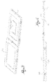
- figure 11 shows an example of stacking of multiple containers on a pallet.
- the folding container according to the present invention exhibits a parallelepiped structure comprising a bottom 11, a cover 12 and four side walls 13, 14, 15 and 16.
- Cover 12 and a first side wall 13 are connected by hinged means 17 for a full folding of the cover on said first wall.
- Cover 12 and a second side wall 14 opposed to the first one have respective locking means 18 engageable with one another in a coupling configuration to constrain the container in the use configuration.
- bottom 11 and the second side wall 14 opposed to the first one are connected by hinged means 17 for a full folding of the bottom on said second wall 14.
- Bottom and the first side wall 13 have respective locking means 18 engageable with one another in a coupling configuration to constrain the container in the use configuration.
- Each of the four side walls 13-16 is in turn connected to the adjacent walls by hinged means 17 adapted for allowing full folding of two adjacent side walls on the other two.
- hinged means 17 adapted for allowing full folding of two adjacent side walls on the other two.
- the hinged means 17 comprise at least one hinge pin 19 on each of the two hinged sides and a joint 20 having two parallel cylindrical seats 21 wherein said pins 19 are turnably seated (figure 6a).
- the two seats 21 present a C shape that allows press application of joint 20 to pins 19. Moreover, the distance between centres of the two seats 21 for pins 19 is selected based on the thickness of the container faces so as to allow complete overlapping of the two hinged faces.
- At least joints 20 that connect the pairs of side walls that, during the folding of the container, open up to forming a flat angle with one another, face towards one of said walls, thus forming two edges at ninety degrees 20' that, acting as stop shoulders, prevent any undesired movement of said wall relative to the joint (figure 9a). This is especially advantageous when the container is totally filled to prevent it from deforming, thus preventing the cover closing.
- the locking means 18 comprise at least one eyebolt 22 obtained on one of the two faces or walls to couple and an elastic hook 23 obtained on the other of said two faces or walls and intended to engage in said eyebolt.
- each elastic hook 23 comprises an elastic tab 23' obtained in a side of the wall to couple and a coupling portion 23" that extends from the free end of said elastic tab (figure 6b).
- the third and the fourth side walls 15, 16 and the two opposed sides of bottom 11 and of cover 12 adjacent to them exhibit respective complementary centring means for an alignment of the bottom and of the cover with said walls during the assembly of the container to the use configuration.
- the complementary centring means comprise at least one tooth 24 extending from at least one side of the side walls 15, 16 and a groove 25 obtained in the corresponding side of the bottom and of the cover for receiving said tooth, or vice versa (figure 8a).
- the third and the fourth side walls 15, 16 and the two opposed sides of bottom 11 adjacent to them exhibit second locking means 26 engageable with one another in a coupling relation.
- said second locking means 26 comprise at least one pin 27 on each of the two sides to constrain and a coupling element 28 turnably constrained to one of said pins and connectable by pressure to the other of said pins (figure 8b).
- bottom 11 and cover 12 exhibit, along the side intended to couple to the respective side walls 13, 14, a horizontal tab 29 adapted for abutting on a lowered portion 30 obtained along the side of said side walls.
- an anti-rotation tooth 31 that, extending from a vertical edge of a wall in a direction orthogonal to it, abuts on the outer face of the adjacent wall, thus limiting said angle in a ninety degree opening.
- an anti-rotation square 34 that, extending from a vertical edge of a wall, abuts on the inner side of the adjacent side wall, thus limiting said angle in a ninety degree closing.
- the container is shaped to allow a steady stacking of multiple containers on top of one another.
- at least one foot 32 extends from bottom 11, preferably four, suitably spaced, for resting on an underlying surface.
- Cover 12 exhibits a lowered central portion adapted for receiving the support foot of a similar container resting on top of it. Said lowered portion 33 serves as a guide for the container above and allows reducing the space occupied in height by multiple stacked containers.
- the side wall on which bottom 11 can be folded also exhibits a lowered central portion 33 adapted for receiving the support foot of the bottom when the container is in the folded configuration.
- the container is fully made of a plastic material. As there are no metal parts and/or other materials, the container is completely recyclable.
- the container according to the present invention can therefore be fully folded starting from the use configuration by simply releasing the cover from the side wall to which it is constrained, by simple pressure on the elastic hooks, tilting the cover on the side wall to which it is hinged, overturning the container, releasing the bottom from the side walls, tilting it on the side wall to which it is hinged, and pressing two opposed edges of the side walls towards one another up to cause the full folding of two side walls on the other two.
- the container when folded, exhibits a height equal to three stacked walls and a maximum width equal to two sided walls, as it is clear in figures 3 and 4.
- the volume reduction between the use and the folded configuration is about 83%.
- the container proposed here can be obtained starting from a single module and that, suitable adapted, can carry out the different functions typical of the six faces of the container. In this way it is possible to obtain the four side walls, the bottom and the cover with a single die fitted with suitable interchangeable inserts.
Landscapes
- Engineering & Computer Science (AREA)
- Mechanical Engineering (AREA)
- Rigid Containers With Two Or More Constituent Elements (AREA)
Applications Claiming Priority (2)
| Application Number | Priority Date | Filing Date | Title |
|---|---|---|---|
| ITBS20040076 | 2004-06-25 | ||
| ITBS20040076 ITBS20040076A1 (it) | 2004-06-25 | 2004-06-25 | Contenitore pieghevole |
Publications (2)
| Publication Number | Publication Date |
|---|---|
| EP1609728A2 true EP1609728A2 (fr) | 2005-12-28 |
| EP1609728A3 EP1609728A3 (fr) | 2009-09-30 |
Family
ID=34978953
Family Applications (1)
| Application Number | Title | Priority Date | Filing Date |
|---|---|---|---|
| EP05100548A Withdrawn EP1609728A3 (fr) | 2004-06-25 | 2005-01-27 | Récipient pliable |
Country Status (2)
| Country | Link |
|---|---|
| EP (1) | EP1609728A3 (fr) |
| IT (1) | ITBS20040076A1 (fr) |
Cited By (3)
| Publication number | Priority date | Publication date | Assignee | Title |
|---|---|---|---|---|
| DE202011106017U1 (de) | 2011-09-22 | 2011-11-24 | Bito-Lagertechnik Bittmann Gmbh | Transport- und Lagerbehälter mit einem Deckel |
| ES2390060A1 (es) * | 2011-04-05 | 2012-11-06 | Universidad De Extremadura | Embalaje reutilizable. |
| KR20190108897A (ko) * | 2018-03-15 | 2019-09-25 | 김용훈 | 다용도 실내 골프 연습용 부스 |
Families Citing this family (1)
| Publication number | Priority date | Publication date | Assignee | Title |
|---|---|---|---|---|
| CN108357751A (zh) * | 2018-02-08 | 2018-08-03 | 李德镇 | 绿色环保折叠式物流快递箱 |
Family Cites Families (8)
| Publication number | Priority date | Publication date | Assignee | Title |
|---|---|---|---|---|
| FR892502A (fr) * | 1943-02-05 | 1944-04-11 | Emballage pliant | |
| BE486724A (fr) * | 1948-04-13 | 1949-01-31 | ||
| GB844723A (en) * | 1958-07-14 | 1960-08-17 | Harold Frank Robins | Improvements in or relating to collapsible boxes and packing cases |
| GB963520A (en) * | 1962-08-04 | 1964-07-08 | Charles William Remnant | Improvements in collapsible boxes or containers |
| DE7726074U1 (de) * | 1977-08-23 | 1977-12-15 | Spumalit Anstalt | Zusammenklappbarer stapelbarer Transportkasten aus Kunststoff |
| FR2428576A3 (fr) * | 1978-05-18 | 1980-01-11 | Tissus Fantaisie Sa | Boite en matiere plastique thermoformee a couvercle amovible emboitable |
| EP0227752A4 (fr) * | 1985-06-18 | 1989-01-17 | John William Swaney | Emballage ameliore pour chaussures. |
| DE3622079A1 (de) * | 1986-05-05 | 1987-11-12 | Werner Cordes | Transportkasten |
-
2004
- 2004-06-25 IT ITBS20040076 patent/ITBS20040076A1/it unknown
-
2005
- 2005-01-27 EP EP05100548A patent/EP1609728A3/fr not_active Withdrawn
Cited By (3)
| Publication number | Priority date | Publication date | Assignee | Title |
|---|---|---|---|---|
| ES2390060A1 (es) * | 2011-04-05 | 2012-11-06 | Universidad De Extremadura | Embalaje reutilizable. |
| DE202011106017U1 (de) | 2011-09-22 | 2011-11-24 | Bito-Lagertechnik Bittmann Gmbh | Transport- und Lagerbehälter mit einem Deckel |
| KR20190108897A (ko) * | 2018-03-15 | 2019-09-25 | 김용훈 | 다용도 실내 골프 연습용 부스 |
Also Published As
| Publication number | Publication date |
|---|---|
| ITBS20040076A1 (it) | 2004-09-25 |
| EP1609728A3 (fr) | 2009-09-30 |
Similar Documents
| Publication | Publication Date | Title |
|---|---|---|
| US7347328B2 (en) | Collapsible container for transport and storage | |
| EP1043239B1 (fr) | Récipient à parois repliables | |
| CN102395514B (zh) | 具有可折叠的带稳固的侧壁结构的侧壁的箱子 | |
| US4674647A (en) | Collapsible storage bin | |
| EP1189814B1 (fr) | Système de conteneurs empilables | |
| EP2256051B1 (fr) | Palette avec parois latérales et couvercle | |
| CN104781152B (zh) | 可折叠金属盒 | |
| JPS624048A (ja) | 折りたたみ式コンテナ | |
| MXPA06013478A (es) | Recipiente de almacenamiento portatil. | |
| AU2008274851A1 (en) | Collapsible plastic container | |
| AU751336B2 (en) | Collapsible container and method for the assembly of such a container | |
| US12479625B2 (en) | Container | |
| EP0631938A2 (fr) | Caisse repliable pour fruits et légumes | |
| EP1609728A2 (fr) | Récipient pliable | |
| US10150587B2 (en) | Hinge assembly and container with such a hinge assembly | |
| EP3911577B1 (fr) | Récipient pliable | |
| EP3259195B1 (fr) | Bac de stockage pliable très résistant | |
| EP3286095B1 (fr) | Récipient de présentation | |
| NL1016882C2 (nl) | Opvouwbare doos met hoekversteviging en plano daarvoor. | |
| JPH068023Y2 (ja) | 合成樹脂製の折りたたみ式コンテナー | |
| NZ543919A (en) | Container and set and method for forming the same | |
| ITMI20001368A1 (it) | Contenitore pieghevole per sfuso | |
| AU613651B2 (en) | Crates for piling in an interlocked manner | |
| EP3887271B1 (fr) | Récipient pliable | |
| JP2559988B2 (ja) | パレット容器 |
Legal Events
| Date | Code | Title | Description |
|---|---|---|---|
| PUAI | Public reference made under article 153(3) epc to a published international application that has entered the european phase |
Free format text: ORIGINAL CODE: 0009012 |
|
| AK | Designated contracting states |
Kind code of ref document: A2 Designated state(s): AT BE BG CH CY CZ DE DK EE ES FI FR GB GR HU IE IS IT LI LT LU MC NL PL PT RO SE SI SK TR |
|
| AX | Request for extension of the european patent |
Extension state: AL BA HR LV MK YU |
|
| RAP1 | Party data changed (applicant data changed or rights of an application transferred) |
Owner name: OMPLAST S.R.L. |
|
| PUAL | Search report despatched |
Free format text: ORIGINAL CODE: 0009013 |
|
| AK | Designated contracting states |
Kind code of ref document: A3 Designated state(s): AT BE BG CH CY CZ DE DK EE ES FI FR GB GR HU IE IS IT LI LT LU MC NL PL PT RO SE SI SK TR |
|
| AX | Request for extension of the european patent |
Extension state: AL BA HR LV MK YU |
|
| RIC1 | Information provided on ipc code assigned before grant |
Ipc: B65D 21/02 20060101ALI20090821BHEP Ipc: B65D 6/20 20060101AFI20050930BHEP |
|
| AKX | Designation fees paid | ||
| REG | Reference to a national code |
Ref country code: DE Ref legal event code: 8566 |
|
| STAA | Information on the status of an ep patent application or granted ep patent |
Free format text: STATUS: THE APPLICATION IS DEEMED TO BE WITHDRAWN |
|
| 18D | Application deemed to be withdrawn |
Effective date: 20100331 |