EP1609730B1 - Bac de stockage pour lettres et objets plats postaux - Google Patents
Bac de stockage pour lettres et objets plats postaux Download PDFInfo
- Publication number
- EP1609730B1 EP1609730B1 EP05300455A EP05300455A EP1609730B1 EP 1609730 B1 EP1609730 B1 EP 1609730B1 EP 05300455 A EP05300455 A EP 05300455A EP 05300455 A EP05300455 A EP 05300455A EP 1609730 B1 EP1609730 B1 EP 1609730B1
- Authority
- EP
- European Patent Office
- Prior art keywords
- bin
- storage bin
- horizontal
- storage
- tray
- Prior art date
- Legal status (The legal status is an assumption and is not a legal conclusion. Google has not performed a legal analysis and makes no representation as to the accuracy of the status listed.)
- Expired - Lifetime
Links
Images


Classifications
-
- B—PERFORMING OPERATIONS; TRANSPORTING
- B65—CONVEYING; PACKING; STORING; HANDLING THIN OR FILAMENTARY MATERIAL
- B65H—HANDLING THIN OR FILAMENTARY MATERIAL, e.g. SHEETS, WEBS, CABLES
- B65H31/00—Pile receivers
- B65H31/02—Pile receivers with stationary end support against which pile accumulates
-
- B—PERFORMING OPERATIONS; TRANSPORTING
- B07—SEPARATING SOLIDS FROM SOLIDS; SORTING
- B07C—POSTAL SORTING; SORTING INDIVIDUAL ARTICLES, OR BULK MATERIAL FIT TO BE SORTED PIECE-MEAL, e.g. BY PICKING
- B07C3/00—Sorting according to destination
- B07C3/008—Means for collecting objects, e.g. containers for sorted mail items
-
- B—PERFORMING OPERATIONS; TRANSPORTING
- B65—CONVEYING; PACKING; STORING; HANDLING THIN OR FILAMENTARY MATERIAL
- B65H—HANDLING THIN OR FILAMENTARY MATERIAL, e.g. SHEETS, WEBS, CABLES
- B65H31/00—Pile receivers
- B65H31/22—Pile receivers removable or interchangeable
-
- B—PERFORMING OPERATIONS; TRANSPORTING
- B65—CONVEYING; PACKING; STORING; HANDLING THIN OR FILAMENTARY MATERIAL
- B65H—HANDLING THIN OR FILAMENTARY MATERIAL, e.g. SHEETS, WEBS, CABLES
- B65H2301/00—Handling processes for sheets or webs
- B65H2301/40—Type of handling process
- B65H2301/42—Piling, depiling, handling piles
- B65H2301/422—Handling piles, sets or stacks of articles
- B65H2301/4225—Handling piles, sets or stacks of articles in or on special supports
- B65H2301/42254—Boxes; Cassettes; Containers
-
- B—PERFORMING OPERATIONS; TRANSPORTING
- B65—CONVEYING; PACKING; STORING; HANDLING THIN OR FILAMENTARY MATERIAL
- B65H—HANDLING THIN OR FILAMENTARY MATERIAL, e.g. SHEETS, WEBS, CABLES
- B65H2405/00—Parts for holding the handled material
- B65H2405/10—Cassettes, holders, bins, decks, trays, supports or magazines for sheets stacked substantially horizontally
- B65H2405/11—Parts and details thereof
- B65H2405/111—Bottom
- B65H2405/1115—Bottom with surface inclined, e.g. in width-wise direction
-
- B—PERFORMING OPERATIONS; TRANSPORTING
- B65—CONVEYING; PACKING; STORING; HANDLING THIN OR FILAMENTARY MATERIAL
- B65H—HANDLING THIN OR FILAMENTARY MATERIAL, e.g. SHEETS, WEBS, CABLES
- B65H2405/00—Parts for holding the handled material
- B65H2405/10—Cassettes, holders, bins, decks, trays, supports or magazines for sheets stacked substantially horizontally
- B65H2405/14—Details of surface
- B65H2405/141—Reliefs, projections
- B65H2405/1412—Ribs extending in parallel to feeding/delivery direction
-
- B—PERFORMING OPERATIONS; TRANSPORTING
- B65—CONVEYING; PACKING; STORING; HANDLING THIN OR FILAMENTARY MATERIAL
- B65H—HANDLING THIN OR FILAMENTARY MATERIAL, e.g. SHEETS, WEBS, CABLES
- B65H2701/00—Handled material; Storage means
- B65H2701/10—Handled articles or webs
- B65H2701/19—Specific article or web
- B65H2701/1916—Envelopes and articles of mail
Definitions
- the present invention relates to a storage bin for postal items comprising a plurality of side walls and a bottom.
- the invention relates to a storage bin for postal items, typically letters and postal flat objects, used for receiving and storing postal items mainly in a sorting machine for postal items with buckets.
- postal items are conveyed by a bucket carousel over a plurality of storage bins constituting the sorting outlets of the sorting machine and are dumped buckets to the storage bins by simply opening the bottom of the buckets as shown in the US-5290025 .
- a mail storage bin comprising a bottom consisting of a wall inclined between two diametrically opposite corners of the tray which allows a better stacking of postal items in the bottom of the tray and a better holding in position of the stack of shipments in the bottom of the tray relative to a bottom horizontal or perpendicular to the side walls of the tray.
- the object of the invention is to provide a storage bin for postal items which does not have the drawbacks mentioned above and in particular which makes it possible to keep the two longitudinal and transverse orientations of the postal items at the outlet of the buckets of the machine. sorting, which keeps the sequence of mail items unloaded by the buckets in the tray, which preserves the integrity of the stack of mail items contained in the tray including during handling operations and automatic conveying of bin and which allows an automatic extraction of the stack of postal items out of the tray.
- the subject of the invention is a storage bin of substantially parallelepiped shape for storing postal items in sorting outlets of a postal sorting machine, comprising a bottom surrounded by side walls defining an upper part. horizontal tray and a lower horizontal portion of the tray, characterized in that the bottom of the tray is constituted by two inclined walls which form in section a "V" having a base disposed in the lower part of the tray and branches that extend towards the upper horizontal part of the tray being inclined relative to the lower horizontal part of the tray, and in that the side walls (7) of the tray flare towards the bottom of the tray.
- the tray according to the invention is designed to have a bottom V-shaped interior with interior walls that define the V which are inclined with respect to the lower horizontal portion of the tray which is outside.
- the side walls (outer walls) widen from the top to the bottom of the tray which allows a stack of V-shaped bottom tanks.
- the upper ends of the two inclined walls (6,8) are offset vertically.
- a first wall of the bottom makes an angle approximately 40 ° to the horizontal and a second wall of the bottom makes an angle of about 70 ° to the horizontal.
- one or both inclined walls of the bottom of the tray is or are openwork.
- one or both inclined walls of the bottom of the tray has or have a corrugated profile.
- one of the inclined walls of the bottom of the tray has a corrugated profile and the other has a perforated profile.
- the bottom of the tray constituted by the two inclined walls is removable relative to the side walls of the tray.
- the invention extends to a machine for sorting mail items with buckets for moving postal items over a plurality of storage bins as defined above.
- Each mailpiece leaving a bucket follows a path until it is received in a storage bin, one of the two inclined walls of a storage tank constituting a jogging wall of postal items in the bottom of the tray and the other two inclined walls of the storage tank constituting a receiving wall of postal items in the bottom of the tray.
- the jogging wall of the tray is inclined so as to be substantially tangent to the path of the mailpiece and the receiving wall of the tray is inclined so as to receive a flat mailing.
- the figure 1 shows schematically a sectional view of a storage tank according to the invention receiving a mail from a bucket in a sorting machine.
- the figure 2 schematically shows a sectional view of a storage bin containing a plurality of heterogeneous postal items stacked in the bottom of the tray.
- the figure 3 shows a sectional view along AA in the figure 1 storage tank according to the invention with inclined walls constituting the bottom of the tray having a crenellated profile.
- the figure 4 shows a perspective view of the storage tank according to the invention with inclined walls constituting the bottom of the tray having a crenellated profile.
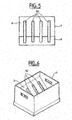
- the figure 5 shows a top view of the storage tank according to the invention with perforated inclined walls constituting the bottom of the tray.
- the figure 6 shows a perspective view of the storage tank according to the invention with perforated inclined walls constituting the bottom of the tray.
- FIG. 1 there is shown a bucket 1 in a mail sorting machine conveying a postal item 2 above a storage bin 3 according to the invention.
- the postal item 2 is placed in the bucket 1 in the direction of the length. It extends substantially vertically with a certain inclination.
- the bucket 1 and thus the mailpiece 2 it contains are, for example, inclined at 60 ° clockwise relative to the horizontal.
- buckets such as 1 move on a carousel (not shown on the figure 1 ) at a speed of about 1 m / s, for example.
- the mailpiece 2 pushed by the bucket 1 On leaving the bucket 1 (the bottom of the bucket being open), the mailpiece 2 pushed by the bucket 1 describes a substantially parabolic trajectory 5 which is illustrated in dashed lines on the figure 1 with the successive positions of the mailpiece 2 until its fall in the bottom of the storage bin 3.
- the trajectory of the mailpiece 2 remains mainly dependent on the orientation and the conveying speed of the bucket 1.
- the postal item 2 is received in the storage tank 3 on a receiving wall indicated by 6 which constitutes a wall of the bottom of the tray.
- the storage tray 3, of substantially parallelepiped shape comprises a plurality of side walls 7, for example four side walls 7 surrounding the bottom of the tray.
- the bottom of the tray according to the invention consists of two walls inclined relative to each other and relative to the horizontal (lower and upper part of the tray horizontally), namely the receiving wall 6 and a jogging wall 8, these two walls forming a "V" in section.
- the receiving wall 6 and the jogging wall 8 respectively correspond to the first and second bars of the "V" shape.
- the inner walls of the tray defining the V-shaped bottom are inclined with respect to the lower part of the tray (horizontal base in dashed line) or to the upper part of the tray (horizontal opening in dashed line).
- the receiving wall 6 is inclined substantially identically to the bucket 1 so that the mailpiece 2 is received flat on the receiving surface 6. As a result, the mailpiece 2 does not bounce and therefore does not change. no orientation at its reception in the bottom of the bucket.
- the inclination of the receiving wall 6 thus depends on the trajectory 5 described above and the drop height of the mailpiece 2 from the bucket 1.
- the depth of the receiving wall 6, that is to say the length of the first bar of the "V" shape, must be greater than the maximum width of the spectrum of postal items considered, for example 300 mm.
- the depth of the receiving wall 6 must also not be too large because a second mailing could be received on the receiving wall 6 above a first mailing previously received, the second mailing could thus pass below the first and corrupt the integrity of the pile.
- the base 9 of the "V" shape should be substantially placed in the bottom of the tray where the mailpiece 2 comes into contact with the storage bin 3.
- the side wall 7 which extends the receiving wall 6 to the top of the tray forms an extension that increases the storage capacity of the tray 3.
- the postal item 2 is received on the receiving wall 6 and slides slightly towards the base 9 of the "V" shape to snap against the jogging wall 8.
- the jogging wall 8 is inclined so as to be substantially tangent to the trajectory of the mailpiece 2 at its reception in the storage bin 3. Thus, the mailpiece sliding on the receiving wall 6 does not go back on
- the jogging wall 8 extends from the base 9 of the "V" shape to the upper end of a side wall 7 and is inclined approximately 70 ° to the horizontal.
- the mailpiece 2 is received flat on the receiving wall 6 without changing its orientation and is tapped on the tangent wall 8 without going back up the tray so that it is possible to form a stable and intact stack of postal items in the bottom of the tray, which can be conveyed automatically or be handled without risk of losing the integrity of the stack.
- the postal items are stacked on edge in the bottom of the tray which allows, if necessary, easy verification of the contents of the storage bin.
- FIG. 2 there is shown a plurality of heterogeneous postal items stacked in the bottom of the storage bin 3. It is understood that by firing against the jogging wall 8, the successive heterogeneous postal items form a stack 10 increasingly flat as the number of postal items increases.
- the height of the stack 10 is equivalent to the length of a line segment perpendicular to the receiving wall 6 and reaching the top of the stack 10.
- a stack height 10 of about 230 mm makes it possible to have a sufficiently stable stack 10 for automatic conveying and storage capacity of the tray 3 satisfactory.
- More storage capacity of the tray 3 can be obtained by means of a larger storage tank 3 and a device for adjusting the position of the bottom of the tray 3 constituted by the receiving wall 6 and the jogging wall 8, therefore to adjust the drop height of the postal items as the postal items pile up in the tray 3 so that the drop height is maintained at a correct value, thereby avoiding the changes in orientation of postal items.
- FIG 3 there is shown a sectional view along AA in the figure 1 storage tank 3, wherein the jogging wall 8 has in section a crenellated profile 30.
- the receiving wall 6 also has in section a crenellated profile.
- the crenellated profile 30 allows, using a device consisting of extraction fingers (not shown in the figure) for example, to pass under the stack of heterogeneous postal items 10 and thus extract the postal items while maintaining the integrity of the stack 10.
- the automatic or manual extraction process can be set up, for example, between the first and the second sorting pass in the sorting machine or when transferring to a machine. tray dedicated to distribution.
- the sectional profile of the receiving wall 6 and / or the jogging wall 8 may be a corrugated profile with a suitable extraction device.
- FIG 4 there is shown a perspective view of the storage tank 3 in which the receiving wall 6 and the jogging wall 8 present in section
- the outer lateral walls of the trough flare out going from the upper part (opening) to the lower part (bottom) of the trough.
- FIG 5 there is shown a top view of the storage tank 3, in which the receiving wall 6 and the jogging wall 8 are perforated by means of a plurality of slots 50 extending from the receiving wall 6 towards the jogging wall 8 for example, so that a device consisting of extraction fingers (not shown in the figure) allows the automatic or manual extraction of the stack of heterogeneous postal items 10 while maintaining the integrity of the stack 10.
- FIG. 6 there is shown a perspective view of the storage tank 3 in which the receiving wall 6 and the jogging wall 8 are perforated by means of a plurality of slots 50 extending from the receiving wall 6 towards the jogging wall 8.
- the receiving wall 6 and the jogging wall 8 may have a perforated profile for one and a corrugated profile for the other.
- the side walls 7 flare out towards the bottom of the storage bin 3. Therefore, when storage bins are not used, they can be stacked on top of each other and fit into each other to occupy a minimum of space.
- a bar code is written on the storage bin 3 in order to identify it and to allow a follow-up of the sequence of the storage bins in the sorting machine.
- the bottom of the storage tank 3 constituted by the receiving wall 6 and the jogging wall 8, is a removable bottom that can be placed in a tray flat-bottomed storage for example.
Landscapes
- Engineering & Computer Science (AREA)
- Mechanical Engineering (AREA)
- Sorting Of Articles (AREA)
- Supports Or Holders For Household Use (AREA)
- Details Of Rigid Or Semi-Rigid Containers (AREA)
- Data Exchanges In Wide-Area Networks (AREA)
Description
- La présente invention concerne un bac de stockage pour des envois postaux comprenant une pluralité de parois latérales et un fond.
- Plus particulièrement, l'invention concerne un bac de stockage d'envois postaux, typiquement des lettres et des objets plats postaux, utilisé pour recevoir et stocker des envois postaux principalement dans une machine de tri d'envois postaux à godets.
- En particulier, dans une machine de tri postal à godets, les envois postaux sont convoyés par un carrousel à godets au-dessus d'une pluralité de bacs de stockage constituant les sorties de tri de la machine de tri et sont déversés des godets vers les bacs de stockage par simple ouverture du fond des godets comme montré dans le
brevet US-5290025 . - On connaît du document de
brevet US-6648284 , un bac de stockage d'envois postaux comprenant un fond constitué par une paroi inclinée entre deux coins diamétralement opposés du bac ce qui permet un meilleur empilement des envois postaux dans le fond du bac et un meilleur maintien en position de la pile d'envois postaux dans le fond du bac par rapport à un fond horizontal ou perpendiculaire au parois latérales du bac. - Cependant, avec cet agencement, les envois postaux ont tendance à rebondir (notamment les envois ouverts comme les magazines) sur une paroi latérale du bac avant de se taquer dans le fond du bac. Plus particulièrement, un envoi postal déversé dans ce type de bac à tendance à tourner avant de se taquer contre une paroi latérale du bac ce qui peut être préjudiciable à la suite du processus de tri automatique de l'envoi postal. En outre, la stabilité de la pile, donc son intégrité, n'est satisfaite que pour des envois postaux plats homogènes alors que les machines de tris actuelles ont comme contrainte de trier des envois postaux hétérogènes, c'est à dire de taille très différente. De plus, l'agencement du bac connu du document précité ne permet pas une extraction automatique de la pile d'envois postaux depuis le bac de stockage ce qui peut être nécessaire lors des opérations de dépilage en entrée de la machine de tri.
- Le but de l'invention est de proposer un bac de stockage pour des envois postaux qui ne présente pas les inconvénients mentionnés ci-dessus et en particulier qui permet de conserver les deux orientations longitudinale et transversale des envois postaux en sortie des godets de la machine de tri, qui permet de conserver la séquence des envois postaux déchargés par les godets dans le bac, qui permet de préserver l'intégrité de la pile d'envois postaux contenus dans le bac y compris lors des opérations de manipulation et de convoyage automatique du bac et qui permet une extraction automatique de la pile d'envois postaux hors du bac.
- A cet effet, l'invention a pour objet un bac de stockage de forme sensiblement parallélépipédique pour le stockage d'envois postaux dans des sorties de tri d'une machine de tri postal, comprenant un fond entouré par des parois latérales définissant une partie supérieure horizontale du bac et une partie inférieure horizontale du bac, caractérisé en ce que le fond du bac est constitué par deux parois inclinées qui forment en section un « V » ayant une base disposée dans la partie inférieure du bac et des branches qui s'étendent vers la partie supérieure horizontale du bac en étant inclinées par rapport à la partie inférieure horizontale du bac, et en ce que les parois latérales (7) du bac s'évasent en allant vers le fond du bac. On comprend donc que le bac selon l'invention est conçu pour avoir un fond à l'intérieur en forme de V avec des parois intérieures qui définissent le V qui se présentent de façon inclinée par rapport à la partie inférieure horizontale du bac qui est à l'extérieur. Les parois latérales (parois extérieures) s'évasent en allant de la partie supérieure vers la partie inférieure du bac ce qui permet un empilage des bacs à fond en forme de V.
- Selon un mode de réalisation particulier du bac de stockage selon l'invention, par rapport à l'horizontale, les extrémités supérieures des deux parois inclinées (6,8) sont décalées verticalement.
- Selon encore un mode de réalisation particulier, en position horizontale de la partie supérieure du bac, une première paroi du fond fait un angle d'environ 40° par rapport à l'horizontale et une seconde paroi du fond fait un angle d'environ 70° par rapport à l'horizontale.
- Selon encore un mode de réalisation particulier, une ou les deux parois inclinées du fond du bac est ou sont ajourées.
- Selon encore un mode de réalisation particulier, une ou les deux parois inclinées du fond du bac a ou ont un profil ondulé.
- Selon encore un mode de réalisation particulier, une des parois inclinées du fond du bac a un profil ondulé et l'autre a un profil ajouré.
- Selon encore un mode de réalisation particulier, le fond du bac constitué par les deux parois inclinées est amovible par rapport aux parois latérales du bac.
- L'invention s'étend à une machine de tri d'envois postaux avec des godets pour déplacer les envois postaux au-dessus d'une pluralité de bacs de stockage tels que définis plus haut. Chaque envoi postal qui quitte un godet suit une trajectoire jusqu'à sa réception dans un bac de stockage, l'une des deux parois inclinées d'un bac de stockage constituant une paroi de taquage des envois postaux dans le fond du bac et l'autre des deux parois inclinées du bac de stockage constituant une paroi de réception des envois postaux dans le fond du bac. La paroi de taquage du bac est inclinée de telle manière à être sensiblement tangente à la trajectoire de l'envoi postal et la paroi de réception du bac est inclinée de telle manière à recevoir un envoi postal à plat.
- Un exemple d'un mode de réalisation particulier du bac de stockage selon l'invention est décrit plus en détail ci-après et illustré par les dessins. Cette description n'est donnée qu'à titre d'exemple indicatif et nullement limitatif de l'invention.
- La
figure 1 montre de façon schématique une vue en section d'un bac de stockage selon l'invention recevant un envoi postal en provenance d'un godet dans une machine de tri. - La
figure 2 montre de façon schématique une vue en section d'un bac de stockage contenant une pluralité d'envois postaux hétérogènes empilés dans le fond du bac. - La
figure 3 montre une vue en coupe selon A-A dans lafigure 1 du bac de stockage selon l'invention avec des parois inclinées constituant le fond du bac ayant un profil en forme de créneaux. - La
figure 4 montre une vue en perspective du bac de stockage selon l'invention avec des parois inclinées constituant le fond du bac ayant un profil en forme de créneaux. - La
figure 5 montre une vue de dessus du bac de stockage selon l'invention avec des parois inclinées ajourées constituant le fond du bac. - La
figure 6 montre une vue en perspective du bac de stockage selon l'invention avec des parois inclinées ajourées constituant le fond du bac. - Sur la
figure 1 , on a représenté un godet 1 dans une machine de tri d'envois postaux convoyant un envoi postal 2 au-dessus d'un bac de stockage 3 selon l'invention. L'envoi postal 2 est placé dans le godet 1 dans le sens de la longueur. Il s'étend sensiblement verticalement avec une certaine inclinaison. Le godet 1 et donc l'envoi postal 2 qu'il contient sont, par exemple, inclinés à 60° dans le sens des aiguilles d'une montre par rapport à l'horizontal. - Dans une machine de tri postal, les godets tel que 1 se déplacent sur un carrousel (non montré sur la
figure 1 ) à la vitesse d'environ 1 m/s, par exemple. Sur lafigure 1 , on a représenté une flèche horizontale 4 allant de droite à gauche pour illustrer le déplacement du godet 1 au-dessus du bac de stockage 3 fixe. - A sa sortie du godet 1 (le fond du godet étant ouvert), l'envoi postal 2 poussé par le godet 1 décrit une trajectoire 5 sensiblement parabolique qui est illustrée en pointillés sur la
figure 1 avec les positions successives de l'envoi postal 2 jusqu'à sa chute dans le fond du bac de stockage 3. Pour un spectre d'envois postaux dont le poids est compris entre environ moins de 10g et environ 3 kg, et dont la largeur est comprise environ entre 90 et 300 mm et la longueur entre environ 100 et 400 mm, la trajectoire de l'envoi postal 2 reste principalement dépendante de l'orientation et de la vitesse de convoyage du godet 1. - L'envoi postal 2 est donc reçu dans le bac de stockage 3 sur une paroi réceptrice indiquée par 6 qui constitue une paroi du fond du bac. Le bac de stockage 3, de forme sensiblement parallélépipédique comprend une pluralité de parois latérales 7, par exemple quatre parois latérales 7 entourant le fond du bac. Le fond du bac selon l'invention est constitué de deux parois inclinées l'une par rapport à l'autre et par rapport à l'horizontale (partie inférieure et supérieure du bac à l'horizontale), à savoir la paroi réceptrice 6 et une paroi de taquage 8, ces deux parois formant un "V" en section. La paroi réceptrice 6 et la paroi de taquage 8 correspondent respectivement à la première et la deuxième barre de la forme en "V". Sur la
figure 1 , on voit que les parois intérieures du bac définissant le fond en forme de V sont inclinés par rapport à la partie inférieure du bac (base horizontale en trait pointillé) ou à la partie supérieure du bac (ouverture horizontale en trait pointillé). - Plus particulièrement, la paroi réceptrice 6 est inclinée de façon sensiblement identique au godet 1 de telle sorte que l'envoi postal 2 soit reçu à plat sur la surface réceptrice 6. Par conséquent, l'envoi postal 2 ne rebondit pas et ne change donc pas d'orientation à sa réception dans le fond du godet. L'inclinaison de la paroi réceptrice 6 dépend donc de la trajectoire 5 décrite ci-dessus et de la hauteur de chute de l'envoi postal 2 depuis le godet 1. On cherche à minimiser la hauteur de chute des envois postaux afin d'éviter les changements d'orientation des envois lors de leur chute et typiquement la distance entre le bas du godet 1 et le haut du bac de stockage 3 sera de préférence égale à environ 100 mm. De plus, la profondeur de la paroi réceptrice 6, c'est à dire la longueur de la première barre de la forme en "V", doit être supérieure à la largeur maximum du spectre d'envois postaux considéré, par exemple 300 mm. La profondeur de la paroi réceptrice 6 ne doit pas non plus être trop grande car un deuxième envoi postal pourrait être reçu sur la paroi réceptrice 6 au-dessus d'un premier envoi postal précédemment reçu, le deuxième envoi postal pourrait ainsi passer en dessous du premier et corrompre l'intégrité de la pile. En outre, la base 9 de la forme en "V" doit être sensiblement placée dans le bas du bac à l'endroit où l'envoi postal 2 entre en contact avec le bac de stockage 3.
- Les expérimentations ont montré que une paroi réceptrice 6 environ inclinée de 40° par rapport à l'horizontale remplissait les contraintes expliquées ci-dessus.
- La paroi latérale 7 qui prolonge la paroi réceptrice 6 vers le haut du bac forme une extension qui permet d'augmenter la capacité de stockage du bac 3.
- En pratique, l'envoi postal 2 est reçu sur la paroi réceptrice 6 et glisse légèrement vers la base 9 de la forme en "V" pour se taquer contre la paroi de taquage 8.
- La paroi de taquage 8 est inclinée de façon à être sensiblement tangente à la trajectoire de l'envoi postal 2 au niveau de sa réception dans le bac de stockage 3. Ainsi, l'envoi postal glissant sur la paroi réceptrice 6 ne remonte pas sur la paroi de taquage 8. Dans un mode de réalisation préféré de l'invention, la paroi de taquage 8 s'étend de la base 9 de la forme en "V" jusqu'à l'extrémité supérieure d'une paroi latérale 7 et est inclinée d'environ 70° par rapport à l'horizontale.
- Avec un tel agencement du bac de stockage selon l'invention, l'envoi postal 2 est reçu à plat sur la paroi réceptrice 6 sans modification de son orientation et se taque sur la paroi tangente 8 sans remonter vers le haut du bac de sorte qu'il est possible de constituer une pile stable et intègre d'envois postaux dans le fond du bac, lequel peut être convoyé de manière automatique ou être manipulé sans risque de perte de l'intégrité de la pile.
- En outre, les envois postaux sont empilés sur chant dans le fond du bac ce qui permet, le cas échéant, une vérification aisée du contenu du bac de stockage.
- Sur la
figure 2 , on a représenté une pluralité d'envois postaux hétérogènes empilés 10 dans le fond du bac de stockage 3. On comprend qu'en se taquant contre la paroi de taquage 8, les envois postaux hétérogènes successifs forment une pile 10 de plus en plus plate au fur et à mesure que le nombre d'envois postaux augmente. La hauteur de la pile 10 équivaut à la longueur d'un segment de droite perpendiculaire à la paroi réceptrice 6 et atteignant le sommet de la pile 10. Une hauteur de pile 10 d'environ 230 mm permet d'avoir une pile 10 suffisamment stable pour un convoyage automatique et une capacité de stockage du bac 3 satisfaisante. - Une plus grande capacité de stockage du bac 3 peut être obtenue au moyen d'un bac de stockage 3 plus grand et d'un dispositif permettant d'ajuster la position du fond du bac 3 constitué par la paroi réceptrice 6 et la paroi de taquage 8, donc d'ajuster la hauteur de chute des envois postaux au fur et à mesure que les envois postaux s'empilent dans le bac 3 de sorte que la hauteur de chute soit maintenue à une valeur correcte, évitant de ce fait les changements d'orientation des envois postaux.
- Sur la
figure 3 , on a représenté une vue en coupe selon A-A dans lafigure 1 du bac de stockage 3, dans laquelle la paroi de taquage 8 présente en section un profil en forme de créneaux 30. Dans un mode de réalisation préféré de l'invention, la paroi réceptrice 6 présente également en section un profil en forme de créneaux. Le profil en forme de créneaux 30 permet, à l'aide d'un dispositif constitué de doigts d'extraction (non montré sur la figure) par exemple, de passer sous la pile d'envois postaux hétérogènes 10 et ainsi d'extraire les envois postaux tout en conservant l'intégrité de la pile 10. Le processus d'extraction automatique ou manuelle peut être mis en place, par exemple, entre la première et la deuxième passe de tri dans la machine de tri ou lors du transbacage vers un bac dédié à la distribution. - Dans un mode de réalisation particulier du bac de stockage 3 selon l'invention, le profil en section de la paroi réceptrice 6 et/ou de la paroi de taquage 8 peut être un profil ondulé avec un dispositif d'extraction adapté.
- Sur la
figure 4 , on a représenté une vue en perspective du bac de stockage 3 dans lequel la paroi réceptrice 6 et la paroi de taquage 8 présentent en section un profil en forme de créneaux 30. Sur cette figure, on voit également que les parois latérales extérieures du bac s'évasent en allant de la partie supérieure (ouverture) vers la partie inférieure (fond) du bac. - Sur la
figure 5 , on a représenté une vue de dessus du bac de stockage 3, dans laquelle la paroi réceptrice 6 et la paroi de taquage 8 sont ajourées au moyen d'une pluralité de lumières 50 se prolongeant de la paroi réceptrice 6 vers la paroi de taquage 8, par exemple, de sorte qu'un dispositif constitué de doigts d'extraction (non montré sur la figure) permette l'extraction automatique ou manuelle de la pile d'envois postaux hétérogènes 10 tout en conservant l'intégrité de la pile 10. - Sur la
figure 6 , on a représenté une vue en perspective du bac de stockage 3 dans lequel la paroi réceptrice 6 et la paroi de taquage 8 sont ajourées au moyen d'une pluralité de lumières 50 se prolongeant de la paroi réceptrice 6 vers la paroi de taquage 8. - Dans un mode de réalisation particulier du bac de stockage 3 selon l'invention, la paroi réceptrice 6 et la paroi de taquage 8 peuvent présenter un profil ajouré pour l'une et un profil ondulé pour l'autre.
- Dans un mode de réalisation préféré du bac de stockage 3 selon l'invention, les parois latérales 7 vont en s'évasant vers le fond du bac de stockage 3. Par conséquent, lorsque des bacs de stockage ne sont pas utilisés, ils peuvent être empilés les uns sur les autres et emboîter les uns dans les autres pour occuper ainsi un minimum d'espace.
- Dans un mode de réalisation particulier du bac de stockage 3 selon l'invention, un code barre est inscrit sur le bac de stockage 3 afin de l'identifier et de permettre un suivi de la séquence des bacs de stockage dans la machine de tri.
- Dans un autre mode de réalisation particulier du bac de stockage 3 selon l'invention, le fond du bac de stockage 3 constitué par la paroi réceptrice 6 et la paroi de taquage 8, est un fond amovible qui peut être mis en place dans un bac de stockage à fond plat par exemple.
Claims (9)
- Bac de stockage (3) de forme sensiblement parallélépipédique pour le stockage d'envois postaux (2) dans des sorties de tri d'une machine de tri postal, comprenant un fond entouré par des parois latérales (7) définissant une partie supérieure horizontale du bac et une partie inférieure horizontale du bac, caractérisé en ce que le fond du bac est constitué par deux parois inclinées (6,8) qui forment en section un « V » ayant une base disposée dans la partie inférieure du bac et des branches qui s'étendent vers la partie supérieure horizontale du bac en étant inclinées par rapport à la partie inférieure horizontale du bac, et en ce que les parois latérales (7) du bac s'évasent en allant vers le fond du bac.
- Bac de stockage selon la revendication 1, dans lequel par rapport à l'horizontale, les extrémités supérieures des deux parois inclinées (6,8) sont décalées verticalement.
- Bac de stockage selon la revendication 1 ou 2, dans lequel en position horizontale de la partie supérieure du bac, une première paroi du fond fait un angle d'environ 40° par rapport à l'horizontale et une seconde paroi du fond fait un angle d'environ 70° par rapport à l'horizontale.
- Bac de stockage selon l'une des revendications 1 à 3, dans lequel une ou les deux parois inclinées (6,8) du fond du bac est ou sont ajourées.
- Bac de stockage selon l'une des revendications 1 à 3, dans lequel une ou les deux parois inclinées (6,8) du fond du bac a ou ont un profil ondulé.
- Bac de stockage selon l'une des revendications 1 à 3, dans lequel une des parois inclinées (6,8) du fond du bac a un profil ondulé et l'autre a un profil ajouré.
- Bac de stockage selon l'une des revendications 1 à 6, dans lequel le fond du bac constitué par les deux parois inclinées (6,8) est amovible par rapport aux parois latérales (7) du bac.
- Machine de tri d'envois postaux comprenant une pluralité de bacs de stockage (3) selon l'une des revendications 1 à 7 et un carrousel à godets (1) pour déplacer les envois postaux au-dessus des bacs, chaque godet (1) étant déplacé de manière à passer successivement au dessus de la paroi de taquage (8) puis de la paroi de réception (6) de chaque bac de stockage et à présenter un envoi au-dessus d'un bac de stockage en ayant le plat de l'envoi qui est sensiblement parallèle à la paroi de réception (6) dudit bac de stockage.
- Machine selon la revendication 8, dans laquelle les bacs de stockage sont disposés de manière que leur partie supérieure soit espacée de la partie inférieure des godets d'une distance d'environ 100 mm.
Applications Claiming Priority (2)
| Application Number | Priority Date | Filing Date | Title |
|---|---|---|---|
| FR0451192 | 2004-06-23 | ||
| FR0451192A FR2872129B1 (fr) | 2004-06-23 | 2004-06-23 | Bac de stockage pour lettres et objets plats postaux |
Publications (2)
| Publication Number | Publication Date |
|---|---|
| EP1609730A1 EP1609730A1 (fr) | 2005-12-28 |
| EP1609730B1 true EP1609730B1 (fr) | 2009-08-12 |
Family
ID=34949500
Family Applications (1)
| Application Number | Title | Priority Date | Filing Date |
|---|---|---|---|
| EP05300455A Expired - Lifetime EP1609730B1 (fr) | 2004-06-23 | 2005-06-06 | Bac de stockage pour lettres et objets plats postaux |
Country Status (7)
| Country | Link |
|---|---|
| US (1) | US7527154B2 (fr) |
| EP (1) | EP1609730B1 (fr) |
| JP (1) | JP4124782B2 (fr) |
| AU (1) | AU2005202724B2 (fr) |
| DE (1) | DE602005015915D1 (fr) |
| FR (1) | FR2872129B1 (fr) |
| NO (1) | NO337259B1 (fr) |
Families Citing this family (10)
| Publication number | Priority date | Publication date | Assignee | Title |
|---|---|---|---|---|
| US7866936B2 (en) * | 2007-05-01 | 2011-01-11 | Northrop Grumman Systems Corporation | System and method for transferring mail between containers |
| US7766171B2 (en) | 2008-02-28 | 2010-08-03 | Northrop Grumman Systems Corporation | Rigid storage tray for flat and letter mail |
| US8047526B2 (en) * | 2008-03-17 | 2011-11-01 | Northrop Grumman Systems Corporation | In-line justifier for letter and flat mail sorter |
| EP2361864B1 (fr) | 2010-02-23 | 2013-11-20 | Neopost Technologies | Dispositif de stockage d'articles de courrier |
| DE102014108207A1 (de) * | 2014-06-11 | 2015-12-17 | Schoeller Allibert Gmbh | Transportmittel, Transport- und Verteilersystem und Verfahren zum Transportieren und Verteilen von Gütern |
| EP3164229A4 (fr) * | 2014-07-02 | 2018-03-07 | Toshiba International Corporation | Procédé et mécanisme pour automatiser le balayage du courrier |
| CN105438747A (zh) * | 2015-12-05 | 2016-03-30 | 重庆市长桥机械制造有限责任公司 | 倾斜式储存装置 |
| FR3055009B1 (fr) * | 2016-08-12 | 2018-07-27 | Solystic | Procede pour fusionner sur table des objets postaux avec des articles de courrier deja tries |
| CN109939953B (zh) * | 2019-03-29 | 2021-02-23 | 尚远春 | 一种适用于消毒供应中心的分类储物装置 |
| CN112224625B (zh) * | 2020-10-27 | 2022-03-08 | 佛山市和阳精密金属制品有限公司 | 一种工件转运装置 |
Family Cites Families (16)
| Publication number | Priority date | Publication date | Assignee | Title |
|---|---|---|---|---|
| US3343725A (en) * | 1965-06-09 | 1967-09-26 | Hoover Ball & Bearing Co | Bottom discharge bin |
| US3637076A (en) * | 1970-01-08 | 1972-01-25 | William E Halopoff | Method of and means for processing mail |
| JPS5130183B2 (fr) | 1973-04-02 | 1976-08-30 | ||
| CH619437A5 (en) | 1975-08-22 | 1980-09-30 | Hoffmann La Roche | Process for the preparation of polyene compounds. |
| WO1986006044A1 (fr) | 1985-04-16 | 1986-10-23 | Wild Heerbrugg Ag | Recipient en plastique avec arete profilee et son procede de fabrication |
| JPH079202B2 (ja) | 1990-05-24 | 1995-02-01 | 株式会社ユニシアジェックス | 内燃機関のアイドル回転速度制御装置 |
| FR2676377B1 (fr) * | 1991-05-14 | 1993-07-23 | Cie Gle Automatisme Cga Hbs | Dispositif de remplissage de caissettes notamment en sortie d'une machine de tri de courrier. |
| FR2679542B1 (fr) * | 1991-07-22 | 1995-02-24 | Cga Hbs | Dispositif de deversement et de rangement sur chant d'objets plats en particulier de plis en sortie d'une machine de tri. |
| US5340100A (en) * | 1992-11-20 | 1994-08-23 | Electrocom Gard Ltd. | Orientation chute for sorting machine |
| DE4240158C1 (de) * | 1992-11-30 | 1994-02-03 | Rc System | Sortieranlagenabgangsvorrichtung |
| DE4416893C1 (de) * | 1994-05-13 | 1995-06-14 | Licentia Gmbh | Leitvorrichtung für Verteilfördereinrichtung |
| DE29507281U1 (de) * | 1995-05-04 | 1995-06-29 | Jagenberg Diana GmbH, 41468 Neuss | Vorrichtung zum Bilden von Paketen aus geschuppt zugeförderten flachen Gegenständen, insbesondere aus zusammengefalteten Schachteln |
| US5666630A (en) * | 1996-06-03 | 1997-09-09 | Xerox Corporation | Unload while run apparatus for a copier/printer |
| US5920025A (en) * | 1997-01-09 | 1999-07-06 | Yamaha Corporation | Automatic accompanying device and method capable of easily modifying accompaniment style |
| US6227536B1 (en) * | 1999-03-26 | 2001-05-08 | Moore North America, Inc. | Receiving tray insert |
| US6241099B1 (en) * | 1999-05-12 | 2001-06-05 | Northrop Grumman Corporation | Flats bundle collator |
-
2004
- 2004-06-23 FR FR0451192A patent/FR2872129B1/fr not_active Expired - Fee Related
-
2005
- 2005-06-06 EP EP05300455A patent/EP1609730B1/fr not_active Expired - Lifetime
- 2005-06-06 DE DE602005015915T patent/DE602005015915D1/de not_active Expired - Lifetime
- 2005-06-20 NO NO20053028A patent/NO337259B1/no not_active IP Right Cessation
- 2005-06-21 JP JP2005180233A patent/JP4124782B2/ja not_active Expired - Fee Related
- 2005-06-22 AU AU2005202724A patent/AU2005202724B2/en not_active Ceased
- 2005-06-22 US US11/157,783 patent/US7527154B2/en not_active Expired - Fee Related
Also Published As
| Publication number | Publication date |
|---|---|
| AU2005202724A1 (en) | 2006-01-12 |
| JP2006006940A (ja) | 2006-01-12 |
| DE602005015915D1 (de) | 2009-09-24 |
| JP4124782B2 (ja) | 2008-07-23 |
| EP1609730A1 (fr) | 2005-12-28 |
| NO20053028D0 (no) | 2005-06-20 |
| FR2872129B1 (fr) | 2008-12-12 |
| FR2872129A1 (fr) | 2005-12-30 |
| US20060113362A1 (en) | 2006-06-01 |
| NO337259B1 (no) | 2016-02-29 |
| US7527154B2 (en) | 2009-05-05 |
| AU2005202724B2 (en) | 2008-01-31 |
| NO20053028L (no) | 2005-12-27 |
Similar Documents
| Publication | Publication Date | Title |
|---|---|---|
| EP1609730B1 (fr) | Bac de stockage pour lettres et objets plats postaux | |
| EP3122477B1 (fr) | Dispositif d'alimentation en articles plats pour un carrousel à godets | |
| EP2222418B1 (fr) | Dispositif pour decharger des bacs par un organe pivotant | |
| EP3722013B1 (fr) | Equipement de tri de colis avec système de permutation de réceptacles en sortie de tri | |
| EP3302829B1 (fr) | Équipement de tri d'objets en sacs | |
| EP3256409A1 (fr) | Procede et systeme de dechargement de colis | |
| EP1427655B1 (fr) | Dispositif de transfert pour convoyeur lineaire | |
| EP3181491B1 (fr) | Bac pour la collecte de déchets | |
| EP1031386B1 (fr) | Goulotte d'évacuation d'objets dans une installation de tri | |
| FR2680121A1 (fr) | Module empileur pour machine de tri postal ou similaire. | |
| EP2152439B1 (fr) | Dispositif support télescopique pour bacs de stockage d'envois postaux | |
| CA2924096A1 (fr) | Equipement de tri postal comportant un magasin d'alimentation avec deux soles superposees | |
| EP2547461B1 (fr) | Procédé pour trier des envois postaux à l'aide de bacs navette à capacité de stockage variable | |
| EP2772457A1 (fr) | Installation d'aide au conditionnement d'articles | |
| EP3393681B1 (fr) | Equipement de tri postal avec un echangeur de bacs navette en forme de diedre orientes de façon oblique | |
| WO2019025677A1 (fr) | Dispositif pour alimenter un magasin de depilage en articles de courrier sur chant | |
| EP2477759B1 (fr) | Machine de tri postal avec un dispositif de recirculation d'articles comprenant une bande à tasseaux | |
| WO2017162933A1 (fr) | Module de sortie de tri pour machine de tri postal | |
| FR2727949A1 (fr) | Distributeur de caisses empilees | |
| FR3161129A1 (fr) | Installation de tri d’objets apte à ordonner les objets en pile dans des réceptacles de tri | |
| EP3842159B1 (fr) | Installation de tri de colis avec un convoyeur à godets à boucle fermée | |
| EP1384969B1 (fr) | Dispositif de saisie de modules de charges propulsives | |
| US6612568B1 (en) | Piling rack for flat parcels | |
| EP0716891A1 (fr) | Dispositif de ramassage et de remplissage de caisses pour documents plats | |
| FR2670474A1 (fr) | Appareil permettant de distribuer un a un des articles stockes sous la forme d'un empilement. |
Legal Events
| Date | Code | Title | Description |
|---|---|---|---|
| PUAI | Public reference made under article 153(3) epc to a published international application that has entered the european phase |
Free format text: ORIGINAL CODE: 0009012 |
|
| AK | Designated contracting states |
Kind code of ref document: A1 Designated state(s): AT BE BG CH CY CZ DE DK EE ES FI FR GB GR HU IE IS IT LI LT LU MC NL PL PT RO SE SI SK TR |
|
| AX | Request for extension of the european patent |
Extension state: AL BA HR LV MK YU |
|
| 17P | Request for examination filed |
Effective date: 20060628 |
|
| AKX | Designation fees paid |
Designated state(s): DE FR GB NL |
|
| GRAP | Despatch of communication of intention to grant a patent |
Free format text: ORIGINAL CODE: EPIDOSNIGR1 |
|
| GRAS | Grant fee paid |
Free format text: ORIGINAL CODE: EPIDOSNIGR3 |
|
| GRAA | (expected) grant |
Free format text: ORIGINAL CODE: 0009210 |
|
| AK | Designated contracting states |
Kind code of ref document: B1 Designated state(s): DE FR GB NL |
|
| REG | Reference to a national code |
Ref country code: GB Ref legal event code: FG4D Free format text: NOT ENGLISH |
|
| REF | Corresponds to: |
Ref document number: 602005015915 Country of ref document: DE Date of ref document: 20090924 Kind code of ref document: P |
|
| PLBE | No opposition filed within time limit |
Free format text: ORIGINAL CODE: 0009261 |
|
| STAA | Information on the status of an ep patent application or granted ep patent |
Free format text: STATUS: NO OPPOSITION FILED WITHIN TIME LIMIT |
|
| 26N | No opposition filed |
Effective date: 20100517 |
|
| REG | Reference to a national code |
Ref country code: FR Ref legal event code: PLFP Year of fee payment: 12 |
|
| PGFP | Annual fee paid to national office [announced via postgrant information from national office to epo] |
Ref country code: DE Payment date: 20160621 Year of fee payment: 12 Ref country code: GB Payment date: 20160621 Year of fee payment: 12 |
|
| PGFP | Annual fee paid to national office [announced via postgrant information from national office to epo] |
Ref country code: NL Payment date: 20160620 Year of fee payment: 12 Ref country code: FR Payment date: 20160616 Year of fee payment: 12 |
|
| REG | Reference to a national code |
Ref country code: DE Ref legal event code: R119 Ref document number: 602005015915 Country of ref document: DE |
|
| REG | Reference to a national code |
Ref country code: NL Ref legal event code: MM Effective date: 20170701 |
|
| GBPC | Gb: european patent ceased through non-payment of renewal fee |
Effective date: 20170606 |
|
| PG25 | Lapsed in a contracting state [announced via postgrant information from national office to epo] |
Ref country code: NL Free format text: LAPSE BECAUSE OF NON-PAYMENT OF DUE FEES Effective date: 20170701 |
|
| REG | Reference to a national code |
Ref country code: FR Ref legal event code: ST Effective date: 20180228 |
|
| PG25 | Lapsed in a contracting state [announced via postgrant information from national office to epo] |
Ref country code: DE Free format text: LAPSE BECAUSE OF NON-PAYMENT OF DUE FEES Effective date: 20180103 Ref country code: GB Free format text: LAPSE BECAUSE OF NON-PAYMENT OF DUE FEES Effective date: 20170606 |
|
| PG25 | Lapsed in a contracting state [announced via postgrant information from national office to epo] |
Ref country code: FR Free format text: LAPSE BECAUSE OF NON-PAYMENT OF DUE FEES Effective date: 20170630 |