EP1609733B1 - Tankstutzen für Einfüllöffnungen von Tanks - Google Patents
Tankstutzen für Einfüllöffnungen von Tanks Download PDFInfo
- Publication number
- EP1609733B1 EP1609733B1 EP04014794A EP04014794A EP1609733B1 EP 1609733 B1 EP1609733 B1 EP 1609733B1 EP 04014794 A EP04014794 A EP 04014794A EP 04014794 A EP04014794 A EP 04014794A EP 1609733 B1 EP1609733 B1 EP 1609733B1
- Authority
- EP
- European Patent Office
- Prior art keywords
- neck
- inner ring
- cylindrical body
- hollow cylindrical
- filler
- Prior art date
- Legal status (The legal status is an assumption and is not a legal conclusion. Google has not performed a legal analysis and makes no representation as to the accuracy of the status listed.)
- Expired - Lifetime
Links
- 239000000945 filler Substances 0.000 title claims abstract description 24
- 238000007789 sealing Methods 0.000 claims abstract description 6
- 239000004033 plastic Substances 0.000 claims description 6
- 229920003023 plastic Polymers 0.000 claims description 6
- ATJFFYVFTNAWJD-UHFFFAOYSA-N Tin Chemical compound [Sn] ATJFFYVFTNAWJD-UHFFFAOYSA-N 0.000 claims 2
- 239000002184 metal Substances 0.000 description 8
- 238000010079 rubber tapping Methods 0.000 description 5
- 239000000565 sealant Substances 0.000 description 4
- 238000004873 anchoring Methods 0.000 description 2
- 230000006835 compression Effects 0.000 description 2
- 238000007906 compression Methods 0.000 description 2
- 238000005260 corrosion Methods 0.000 description 2
- 230000007797 corrosion Effects 0.000 description 2
- 230000000284 resting effect Effects 0.000 description 2
- 239000007788 liquid Substances 0.000 description 1
- 238000000034 method Methods 0.000 description 1
- 238000003466 welding Methods 0.000 description 1
Images

Classifications
-
- B—PERFORMING OPERATIONS; TRANSPORTING
- B60—VEHICLES IN GENERAL
- B60K—ARRANGEMENT OR MOUNTING OF PROPULSION UNITS OR OF TRANSMISSIONS IN VEHICLES; ARRANGEMENT OR MOUNTING OF PLURAL DIVERSE PRIME-MOVERS IN VEHICLES; AUXILIARY DRIVES FOR VEHICLES; INSTRUMENTATION OR DASHBOARDS FOR VEHICLES; ARRANGEMENTS IN CONNECTION WITH COOLING, AIR INTAKE, GAS EXHAUST OR FUEL SUPPLY OF PROPULSION UNITS IN VEHICLES
- B60K15/00—Arrangement in connection with fuel supply of combustion engines or other fuel consuming energy converters, e.g. fuel cells; Mounting or construction of fuel tanks
- B60K15/03—Fuel tanks
- B60K15/04—Tank inlets
-
- B—PERFORMING OPERATIONS; TRANSPORTING
- B60—VEHICLES IN GENERAL
- B60K—ARRANGEMENT OR MOUNTING OF PROPULSION UNITS OR OF TRANSMISSIONS IN VEHICLES; ARRANGEMENT OR MOUNTING OF PLURAL DIVERSE PRIME-MOVERS IN VEHICLES; AUXILIARY DRIVES FOR VEHICLES; INSTRUMENTATION OR DASHBOARDS FOR VEHICLES; ARRANGEMENTS IN CONNECTION WITH COOLING, AIR INTAKE, GAS EXHAUST OR FUEL SUPPLY OF PROPULSION UNITS IN VEHICLES
- B60K15/00—Arrangement in connection with fuel supply of combustion engines or other fuel consuming energy converters, e.g. fuel cells; Mounting or construction of fuel tanks
- B60K15/03—Fuel tanks
- B60K15/04—Tank inlets
- B60K2015/0458—Details of the tank inlet
- B60K2015/0474—Arrangement of fuel filler pipes in relation to vehicle body
Definitions
- the invention relates to filler neck for filling openings of tanks with the features of the preamble of claim 1.
- a filler neck for filling openings of tanks is known with a closure sleeve, which is arranged against rotation, including a sealant on a neck extension of the filling opening.
- the closure sleeve is formed as a hollow cylindrical body with an outer wall which bears against the outside of the filling opening, a substantially inner closure portion and a separate inner ring, which has a support surface directed radially to the filling opening with devices for mounting on the neck extension for resting on the neck projection.
- the hollow cylindrical body and the inner ring of this prior art are each separately secured against rotation on complicated shaped and therefore expensive to produce neck.
- the voltage applied to the filling outer wall of the hollow cylindrical body should be flexible for mounting on the neck of the tank and still seal with the sealant the tank absolutely reliable to the outside.
- filler neck for filling openings of tanks made of recyclable plastic are problematic in terms of high demands on tightness.
- the object of the invention is to provide filler neck for filling openings of tanks that are simple and inexpensive to build, with improved tightness, stability and durability.
- a filler neck for filling openings of tanks in particular of tanks made of recyclable plastic, provided with a closure sleeve which is arranged against rotation including a sealant on a neck extension of the filling opening, wherein the closure sleeve is formed as a hollow cylindrical body with an outside of the Filling opening adjacent outer wall, a substantially inner closure portion and a separate inner ring, which has a support surface directed radially to the filling opening with support means for mounting on the neck extension for resting on the neck approach.
- the separate inner ring has a brim directed coaxially with the filling opening, which is in contact with the hollow cylindrical body and is compressed at least at one point in the radial direction with the hollow cylindrical body so that local deformations around the at least one point fix the separate inner ring to position the hollow cylindrical body.
- the coaxial with the filling opening on the surface of the hollow cylindrical body inside abutting brim advantageously improves the stability of the outside of the filling opening adjacent the outer wall of the hollow cylindrical Body and thus their suitability for improved tightness of the tank filler neck according to the invention.
- the local deformations in the brim and hollow cylindrical body guided in the radial direction by compression in the radial direction, which position the separate inner ring reliably and firmly to the hollow cylindrical body, are inexpensive to produce, stiffen the inner ring and hollow cylindrical body for improved stability and tightness and are corrosion resistant for a long time as opposed to spot welding, as suggested in the EP 0 229 260 for closure sleeve and anchoring ring, which, especially in connection with aggressive tank liquids, lead to corrosion of the closure sleeve and anchoring ring as a consequence of leaking seal and thus to total failure of the filler neck and tank.
- the filler neck according to the invention with inner ring and hollow cylindrical body is inexpensive to produce.
- the filler neck according to the invention fulfills in particular the high requirements in terms of tightness of tanks made of recyclable plastic.
- the brim is over 360 ° flat on the hollow cylindrical body inside fitting for improved rotationally symmetric stability and tightness.
- the sealing means is a coaxial radial to the filling opening, an O- or a quad ring, etc., which seals radially on the outer wall and is held in the axial direction of the filling opening of the bearing surface of the inner ring on the neck so that Sealant is not pressed by the bearing surface of the inner ring.
- the devices for mounting the inner ring on the neck extension comprise at least one sheet metal fastener, which is adapted to the inner circumference of the neck extension and extends in total only over a fraction of the circumference of the filling opening.
- the sheet metal fastening at least one Y-shaped spread leg, a web and a mounting portion and the mounting portion is provided with a bore for a screw to the bearing surface of the inner ring.
- the sheet metal fasteners are inexpensive to produce and can be cast or pressed radially inwardly in the neck neck of the filling opening cost for a means of preferably releasable screws mounting the inner ring with the hollow cylindrical body on the neck of the filling opening.
- a filler neck 1 of a filling opening of a tank 2 of recyclable plastic has a metallic sealing sleeve 3, which is arranged on a neck neck 4 of the filling opening so as to be secure against rotation.
- the closure sleeve 3 is formed as a hollow cylindrical body 5 with a outside on the neck lug 4 of the filling opening adjacent the outer wall 6, a substantially inner closure portion 7 with bayonet lock for a cover (not shown) and a separate, substantially rotationally symmetrical inner ring 8, which is for support the neck lug 4 has a radially directed to the filling opening bearing surface 9 with holes 10 for receiving lens tapping screws 11 as devices for mounting on the neck lug 4.
- the separate inner ring 8 has a brim, which is directed coaxially to the filling opening, which is substantially in contact with the hollow cylindrical body 5 over an area of 360 ° and is compressed pointwise in the radial direction with the hollow cylindrical body 5 in such a way that local deformations (not shown) occur. position the separate inner ring 8 firmly on the hollow cylindrical body 5 by at least one point 20 of the compression.
- a radial seal 13 coaxial with the filling opening seals with two radial lips on the inside of the outer wall 6 and is held in the axial direction of the filling opening by the bearing surface of the inner ring 8 on the neck lug 4.
- an O-ring or a quad ring, etc. may seal to the outer wall 6.
- two sheet metal fasteners 14 are adapted in a form-fitting manner to the inner circumference of the neck lug 4.
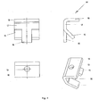
- Fig. 4 10 The sheet metal fasteners 14 are measured to rest on a circumferential section of about 10 ° of the inner circumference of the neck lug 4 and have Y-shaped spread legs 15, 16, a web 17 and a mounting portion 18.
- the mounting portion 18 is provided with a bore 19 for a screw 11 for rotationally fixed attachment of the bearing surface of the inner ring 8 at the neck lug 4.
- the neck lug 4 of the tank 2 made of recyclable plastic is formed with the groove for the radial seal 13 and blind holes for lens tapping screws 11.
- On the blind holes for the lens tapping screws 11 are the two sheet metal fasteners 14 with the legs Y-shaped spread 15, 16th and ridge portion 17 positively adapted to the inner periphery of the neck lug 4, that each of the bore 19 in the mounting portion 18 is coaxial with one of the blind holes for the lens tapping screws 11.
- Radial seal 13 is inserted into the groove on the neck lug 4.
- the inner ring 8 is pressed with its brim 12 flat on the hollow cylindrical body 5 inside abutting pointwise in the radial direction with the hollow cylindrical body, the bearing surface of the inner ring 8 through the holes 19 in the mounting portion 18 of the sheet metal fasteners Positioned 14, the outer wall 6 of the filler neck 1 pushed over the radial seal 13 and the neck lug 4 until the contact surface 9 on the neck lug 4 and with the lens tapping screws 11 of the hollow cylindrical body 5 in the blind holes of the neck lug 4 secured against rotation and releasably.
Landscapes
- Engineering & Computer Science (AREA)
- Life Sciences & Earth Sciences (AREA)
- Sustainable Development (AREA)
- Sustainable Energy (AREA)
- Chemical & Material Sciences (AREA)
- Combustion & Propulsion (AREA)
- Transportation (AREA)
- Mechanical Engineering (AREA)
- Closures For Containers (AREA)
- Filling Of Jars Or Cans And Processes For Cleaning And Sealing Jars (AREA)
- Filling Or Discharging Of Gas Storage Vessels (AREA)
- Level Indicators Using A Float (AREA)
Description
- Die Erfindung betrifft Tankstutzen für Einfüllöffnungen von Tanks mit den Merkmalen des Oberbegriffs des Anspruchs 1.
- Aus der
EP 0304579 ist ein Tankstutzen bekannt mit den Merkmalen des Oberbegriffs des Anspruchs 1. - Aus der G 94 06 095.9 ist ein Tankstutzen für Einfüllöffnungen von Tanks bekannt mit einer Verschlusshülse, die unter Einschluss eines Dichtmittels verdrehsicher auf einem Halsansatz der Einfüllöffnung angeordnet ist. Die Verschlusshülse ist als hohlzylindrischer Körper ausgebildet mit einer außen an der Einfüllöffnung anliegenden Außenwand, einem im wesentlichen innenliegenden Verschlussanteil und einem separaten Innenring, der zur Auflage auf dem Halsansatz eine radial zur Einfüllöffnung gerichtete Auflagefläche mit Vorrichtungen zur Montage auf dem Halsansatz aufweist. Der hohlzylindrischer Körper und der Innenring dieses Standes der Technik sind jeweils gesondert gegen Verdrehung am kompliziert geformten und daher aufwendig herzustellenden Halsansatz gesichert. Die an der Einfüllöffnung anliegende Außenwand des hohlzylindrischen Körpers soll für die Montage auf den Halsansatz des Tanks biegsam sein und dabei dennoch mit dem Dichtmittel den Tank absolut zuverlässig nach außen abdichten. Insbesondere Tankstutzen für Einfüllöffnungen von Tanks aus recyclefähigem Kunststoff sind hinsichtlich der hohen Anforderungen an Dichtigkeit problematisch.
- Aufgabe der Erfindung ist es, Tankstutzen für Einfüllöffnungen von Tanks zu schaffen, die einfach und kostengünstig im Aufbau sind, bei verbesserter Dichtigkeit, Stabilität und Lebensdauer.
- Die Lösung erfolgt mit Tankstutzen für Einfüllöffnungen von Tanks mit den Merkmalen des Anspruchs 1. Vorteilhafte Ausgestaltungen der Erfindung sind in den Unteransprüchen dargestellt.
- Gemäß der Erfindung ist ein Tankstutzen für Einfüllöffnungen von Tanks, insbesondere von Tanks aus recyclefähigem Kunststoff, vorgesehen mit einer Verschlusshülse, die unter Einschluss eines Dichtmittels verdrehsicher auf einem Halsansatz der Einfüllöffnung angeordnet ist, wobei die Verschlusshülse als hohlzylindrischer Körper ausgebildet ist mit einer außen an der Einfüllöffnung anliegenden Aussenwandung, einem im wesentlichen innenliegenden Verschlussanteil und einem separaten Innenring, der zur Auflage auf dem Halsansatz eine radial zur Einfüllöffnung gerichtete Auflagefläche mit Vorrichtungen zur Montage auf dem Halsansatz aufweist. Erfindungsgemäß weist der separate Innenring eine koaxial zur Einfüllöffnung gerichtete Krempe auf, die flächig an dem hohlzylindrischen Körper innen anliegend ist und zumindest an einem Punkt in radialer Richtung so mit dem hohlzylindrischen Körper verpresst ist, dass lokale Verformungen um den mindesten einen Punkt den separaten Innenring fest zum hohlzylindrischen Körper positionieren. Die koaxial zur Einfüllöffnung flächig an dem hohlzylindrischen Körper innen anliegende Krempe verbessert vorteilhaft die Stabilität der außen an der Einfüllöffnung anliegenden Außenwand des hohlzylindrischen Körpers und damit deren Eignung für verbesserte Dichtigkeit des erfindungsgemäßen Tankstutzens. Die gemäß der Erfindung in radialer Richtung durch Verpressen herbei geführten lokalen Verformungen in Krempe und hohlzylindrischem Körper, die den separaten Innenring zuverlässig und fest zum hohlzylindrischen Körper positionieren, sind kostengünstig herzustellen, versteifen Innenring und hohlzylindrischen Körper für verbesserte Stabilität und Dichtigkeit und sind lang andauernd korrosionsbeständig im Gegensatz etwa zu Punktschweißungen, wie vorgeschlagen in der
EP 0 229 260 für Verschlusshülse und Verankerungsring, die insbesondere in Verbindung mit aggressiven Tankflüssigkeiten, zu Korrosion von Verschlusshülse und Verankerungsring in der Folge zu versagender Dichtigkeit und damit zu versagender Gesamtfunktion von Tankstutzen und Tank führen. Der Tankstutzen gemäß der Erfindung mit Innenring und hohlzylindrischem Körper ist kostengünstig herstellbar. Der erfindungsgemäße Tankstutzen erfüllt insbesondere die hohen Anforderungen hinsichtlich Dichtigkeit von Tanks aus recyclefähigem Kunststoff. - Gemäß einer bevorzugten Ausgestaltung der Erfindung ist die Krempe über 360° flächig an dem hohlzylindrischen Körper innen anliegend für verbesserte rotationssymmetrische Stabilität und Dichtigkeit.
- Gemäß einer weiteren bevorzugten Ausgestaltung der Erfindung ist das Dichtmittel eine zur Einfüllöffnung koaxiale Radialdichtung, ein O- oder ein Quad-Ring, etc., die radial an der Aussenwandung innen abdichtet und in axialer Richtung der Einfüllöffnung von der Auflagefläche des Innenrings am Halsansatz gehalten ist, so dass das Dichtmittel von der Auflagefläche des Innenrings nicht gepresst wird.
- Gemäß einer weiteren bevorzugten Ausgestaltung der Erfindung umfassen die Vorrichtungen zur Montage des Innenrings auf dem Halsansatz mindestens eine Blechbefestigung, die formschlüssig an den Innenumfang des Halsansatzes angepasst ist und sich insgesamt nur über einen Bruchteil des Umfangs der Einfüllöffnung erstreckt.
- Gemäß einer weiteren bevorzugten Ausgestaltung der Erfindung weist die Blechbefestigung mindestens einen Y-förmig gespreizten Schenkel, einen Steg- und einen Montageabschnitt auf und der Montageabschnitt mit einer Bohrung für eine Schraube zur Auflagefläche des Innenrings versehen ist. Die Blechbefestigungen sind kostengünstig herstellbar und können kostengünstig radial innenliegend in den Halsansatz der Einfüllöffnung eingegossen oder eingepresst werden für eine mittels vorzugsweise Schrauben lösbare Montage des Innenrings mit dem hohlzylindrischem Körper auf dem Halsansatz der Einfüllöffnung.
- Die Erfindung wird im Folgenden anhand eines bevorzugten Ausführungsbeispiels dargestellt. Es zeigen:
- Fig. 1
- eine teilweise aufgeschnittene Ansicht des Tankstutzens der Erfindung,
- Fig. 2
- einen Querschnitt durch den Tankstutzen der Erfindung,
- Fig. 3
- eine Draufsicht auf den Tankstutzen der Erfindung, und
- Fig. 4
- vergrößerte Ansichten einer Blechbefestigung des Tankstutzens der Erfindung.
-
Fig. 1, 2, 3 : Ein Tankstutzen 1 einer Einfüllöffnung eines Tanks 2 aus recyclefähigem Kunststoff weist eine metallische Verschlusshülse 3 auf, die verdrehsicher auf einem Halsansatz 4 der Einfüllöffnung angeordnet ist. Die Verschlusshülse 3 ist als hohlzylindrischer Körper 5 ausgebildet mit einer außen am Halsansatz 4 der Einfüllöffnung anliegenden Außenwand 6, einem im wesentlichen innenliegenden Verschlussanteil 7 mit Bajonettverschluss für einen Deckel (nicht dargestellt) und einen separaten, im wesentlichen rotationssymmetrischen Innenring 8, der zur Auflage auf dem Halsansatz 4 eine radial zur Einfüllöffnung gerichtete Auflagefläche 9 mit Bohrungen 10 zur Aufnahme von Linsen-Blechschrauben 11 als Vorrichtungen zur Montage auf dem Halsansatz 4 aufweist. - Der separate Innenring 8 weist eine koaxial zur Einfüllöffnung gerichtete Krempe 12 auf, die im wesentlichen über 360° flächig an dem hohlzylindrischen Körper 5 innen anliegend ist und punktweise in radialer Richtung so mit dem hohlzylindrischen Körper 5 verpresst ist, dass lokale Verformungen (nicht dargestellt) um den mindesten einen Punkt 20 der Verpressung den separaten Innenring 8 fest am hohlzylindrischen Körper 5 positionieren.
- Eine zur Einfüllöffnung koaxiale Radialdichtung 13 dichtet mit zwei radialen Lippen innen an der Außenwand 6 ab und ist in axialer Richtung der Einfüllöffnung von der Auflagefläche des Innenrings 8 am Halsansatz 4 gehalten.
- Alternativ können ein O-Ring oder ein Quad-Ring, etc. an der Außenwand 6 abdichten.
- Zur Montage des Innenrings 8 auf dem Halsansatz 4 sind zwei Blechbefestigungen 14 formschlüssig an den Innenumfang des Halsansatzes 4 angepasst.
-
Fig. 4 : Die Blechbefestigungen 14 sind zur Anlage an einen Umfangsausschnitt von ca. 10° des Innenumfangs des Halsansatzes 4 abgemessen und weisen Y-förmig gespreizte Schenkel 15, 16, einen Steg- 17 und einen Montageabschnitt 18 auf. Der Montageabschnitt 18 ist mit einer Bohrung 19 für eine Schraube 11 zur verdrehfesten Befestigung der Auflagefläche des Innenrings 8 am Halsansatz 4 vorgesehen. - Der Halsansatz 4 des Tanks 2 aus recyclefähigem Kunststoff wird geformt mit der Nut für die Radialdichtung 13 und Sacklöchern für Linsen-Blechschrauben 11. Auf die Sacklöcher für die Linsen-Blechschrauben 11 werden die zwei Blechbefestigungen 14 mit den Y-förmig gespreizten Schenkeln 15, 16 und Stegabschnitt 17 formschlüssig so an den Innenumfang des Halsansatzes 4 angepasst, dass jeweils die Bohrung 19 im Montageabschnitt 18 koaxial ist zu einem der Sacklöcher für die Linsen-Blechschrauben 11. Radialdichtung 13 wird in die Nut am Halsansatz 4 eingesetzt.
- Der Innenring 8 wird mit seiner Krempe 12 flächig an dem hohlzylindrischen Körper 5 innen anliegend punktweise in radialer Richtung mit dem hohlzylindrischen Körper verpresst, die Auflagefläche des Innenrings 8 über die Bohrungen 19 im Montageabschnitt 18 der Blechbefestigungen 14 positioniert, die Außenwand 6 des Tankstutzens 1 über die Radialdichtung 13 und den Halsansatz 4 geschoben bis zur Anlage der Auflagefläche 9 auf dem Halsansatz 4 und mit den Linsen-Blechschrauben 11 der hohlzylindrische Körper 5 in den Sacklöchern des Halsansatzes 4 verdrehsicher und lösbar befestigt.
Claims (6)
- Tankstutzen (1) für Einfüllöffnungen von Tanks (2) mit einer Verschlusshülse (3), die unter Einschluss eines Dichtmittels (13) verdrehsicher auf einem Halsansatz (4) der Einfüllöffnung angeordnet ist, wobei die Verschlusshülse (3) als hohlzylindrischer Körper (5) ausgebildet ist mit einer außen an der Einfüllöffnung anliegenden Außenwand (6), einem im wesentlichen innenliegenden Verschlussanteil (7) und einem separaten Innenring (8), der zur Auflage auf dem Halsansatz (4) eine radial zur Einfüllöffnung gerichtete Auflagefläche (9) mit Vorrichtungen (10, 11) zur Montage auf dem Halsansatz (4) aufweist,
dadurch, gekennzeichnet, dass der separate Innenring (8) eine koaxial zur Einfüllöffnung gerichtete Krempe (12) aufweist, die im wesentlichen flächig an dem hohlzylindrischen Körper (5) innen anliegend ist und zumindest an einem Punkt (20) in radialer Richtung so mit dem hohlzylindrischen Körper (5) verpresst ist, dass lokale Verformungen um den mindesten einen Punkt den separaten Innenring (8) fest zum hohlzylindrischen Körper (5) positionieren. - Tankstutzen (1) gemäß Anspruch 1, dadurch gekennzeichnet, dass die Krempe (12) über 360° flächig an dem hohlzylindrischen Körper (5) innen anliegend ist.
- Tankstutzen (1) gemäß Anspruch 1, dadurch gekennzeichnet, dass das Dichtmittel eine Radialdichtung (13), ein O-Ring oder ein Quad-Ring ist, die radial an der Außenwand (6) innen und axial an der Auflagefläche (9) des Innenrings (8) anliegend ist.
- Tankstutzen (1) gemäß Anspruch 1, dadurch gekennzeichnet, dass die Vorrichtungen (10, 11) zur Montage des Innenrings (8) auf dem Halsansatz (4) mindestens eine Blechbefestigung (14) umfassen, die formschlüssig an den Innenumfang des Halsansatzes (4) angepasst ist und sich insgesamt nur über einen Bruchteil des Umfangs der Einfüllöffnung erstreckt.
- Tankstutzen (1) gemäß Anspruch 4, dadurch gekennzeichnet, dass die Blechbefestigung (14) mindestens einen Y-förmig gespreizten Schenkel (15, 16), einen Steg- (17) und einen Montageabschnitt (18) aufweist und der Montageabschnitt (18) mit einer Bohrung (19) für eine Schraube (11) zur Auflagefläche (9) des Innenrings (8) versehen ist.
- Tankstutzen (1) gemäß Anspruch 1, dadurch gekennzeichnet, dass er geeignet ist für aus recyclefähigem Kunststoff hergestellte Tanks.
Priority Applications (3)
| Application Number | Priority Date | Filing Date | Title |
|---|---|---|---|
| AT04014794T ATE408561T1 (de) | 2004-06-24 | 2004-06-24 | Tankstutzen für einfüllöffnungen von tanks |
| EP04014794A EP1609733B1 (de) | 2004-06-24 | 2004-06-24 | Tankstutzen für Einfüllöffnungen von Tanks |
| DE502004008083T DE502004008083D1 (de) | 2004-06-24 | 2004-06-24 | Tankstutzen für Einfüllöffnungen von Tanks |
Applications Claiming Priority (1)
| Application Number | Priority Date | Filing Date | Title |
|---|---|---|---|
| EP04014794A EP1609733B1 (de) | 2004-06-24 | 2004-06-24 | Tankstutzen für Einfüllöffnungen von Tanks |
Publications (2)
| Publication Number | Publication Date |
|---|---|
| EP1609733A1 EP1609733A1 (de) | 2005-12-28 |
| EP1609733B1 true EP1609733B1 (de) | 2008-09-17 |
Family
ID=34925471
Family Applications (1)
| Application Number | Title | Priority Date | Filing Date |
|---|---|---|---|
| EP04014794A Expired - Lifetime EP1609733B1 (de) | 2004-06-24 | 2004-06-24 | Tankstutzen für Einfüllöffnungen von Tanks |
Country Status (3)
| Country | Link |
|---|---|
| EP (1) | EP1609733B1 (de) |
| AT (1) | ATE408561T1 (de) |
| DE (1) | DE502004008083D1 (de) |
Families Citing this family (1)
| Publication number | Priority date | Publication date | Assignee | Title |
|---|---|---|---|---|
| CN114290896A (zh) * | 2022-01-11 | 2022-04-08 | 青岛罗泰克亿利汽车橡塑制品有限公司 | 一种滚塑密封镶件 |
Family Cites Families (5)
| Publication number | Priority date | Publication date | Assignee | Title |
|---|---|---|---|---|
| US2916311A (en) * | 1954-09-15 | 1959-12-08 | American Flange & Mfg | Resilient-collar-type closure for steel shipping and other metallic containers |
| DE8600892U1 (de) | 1986-01-16 | 1986-02-27 | Rhein-Conti Kunststoff-Technik Gmbh, 6900 Heidelberg | Einfüllstutzen mit Deckel mit einrotierter, eingegossener, eingepreßter oder eingespritzter Hülse für Kunststofftankbehälter |
| DE8710813U1 (de) * | 1987-08-07 | 1987-09-24 | Rhein-Conti Kunststoff-Technik Gmbh, 6900 Heidelberg | Tankstutzen mit Verschraubung von oben |
| EP0496766A1 (de) * | 1989-10-22 | 1992-08-05 | Fraunhofer-Gesellschaft Zur Förderung Der Angewandten Forschung E.V. | Spundbehälter |
| DE9406095U1 (de) | 1994-04-13 | 1995-08-10 | Rhein-Bonar Kunststoff-Technik GmbH, 68766 Hockenheim | Einfüllstutzen von Kunststofftanks |
-
2004
- 2004-06-24 DE DE502004008083T patent/DE502004008083D1/de not_active Expired - Fee Related
- 2004-06-24 AT AT04014794T patent/ATE408561T1/de not_active IP Right Cessation
- 2004-06-24 EP EP04014794A patent/EP1609733B1/de not_active Expired - Lifetime
Also Published As
| Publication number | Publication date |
|---|---|
| EP1609733A1 (de) | 2005-12-28 |
| DE502004008083D1 (de) | 2008-10-30 |
| ATE408561T1 (de) | 2008-10-15 |
Similar Documents
| Publication | Publication Date | Title |
|---|---|---|
| DE102006061120B4 (de) | Keg | |
| DE102010009179A1 (de) | Verbindungsvorrichtung zum Verbinden eines flexiblen Gebindes mit einem Flansch oder einem Anschlussring | |
| DE10201652B4 (de) | Kraftstoffbehälter mit Deckel | |
| EP2256365A2 (de) | Zylinderanordnung | |
| EP1828628B1 (de) | Kugelgelenk, vorzugsweise für einen einsatz in fahrzeugen | |
| EP3376087B1 (de) | Verschraubbarer abzweig für ein unebenheiten aufweisendes kanalrohr | |
| EP1388451B1 (de) | Öleinfülleinrichtung an einer Brennkraftmaschine | |
| EP1609733A1 (de) | Tankstutzen für Einfüllöffnungen von Tanks | |
| EP0210322A1 (de) | Tankstutzen | |
| EP2628937B1 (de) | Abdeckhaube am aussenumfang eines betriebsstofftanks | |
| EP1291222B1 (de) | Kraftstoffbehälter | |
| DE102017209890A1 (de) | Kugelgelenk für einen Zweipunktlenker sowie Zweipunktlenker mit einem solchen Kugelgelenk | |
| DE102017203616B4 (de) | Eintaucharmatur zur Positionierung von Messsensoren in Prozessflüssigkeiten | |
| DE29711143U1 (de) | Lager, insbesondere für eine Spannvorrichtung | |
| EP0579145B1 (de) | Abdichtungsvorrichtung für Treibstoffdämpfe aus einem Tankstutzen eines Kraftfahrzeugs | |
| EP1614951A2 (de) | Wandarmatur zur Bildung eines fluidführenden Anschlusses | |
| EP0863338B1 (de) | Ventil | |
| DE102006059397B4 (de) | Dichtung | |
| EP4000980B1 (de) | Drucksensoraufnahme | |
| DE202021106732U1 (de) | Hygiene-Verschluss für Standrohre sowie Anordnung aus Standrohr und Hygiene-Verschluss | |
| DE202006005369U1 (de) | Absperrarmatur | |
| EP2489793A1 (de) | Spülkastenanordnung | |
| DE29803404U1 (de) | Betätigungsgestänge | |
| DE6809955U (de) | Lagerung bei kreiselpumpen mit einem am ende einer antriebswelle sitzenden pumpenrad | |
| DE102004014078A1 (de) | Scheibenwischeranlage |
Legal Events
| Date | Code | Title | Description |
|---|---|---|---|
| PUAI | Public reference made under article 153(3) epc to a published international application that has entered the european phase |
Free format text: ORIGINAL CODE: 0009012 |
|
| AK | Designated contracting states |
Kind code of ref document: A1 Designated state(s): AT BE BG CH CY CZ DE DK EE ES FI FR GB GR HU IE IT LI LU MC NL PL PT RO SE SI SK TR |
|
| AX | Request for extension of the european patent |
Extension state: AL HR LT LV MK |
|
| 17P | Request for examination filed |
Effective date: 20060622 |
|
| AKX | Designation fees paid |
Designated state(s): AT BE BG CH CY CZ DE DK EE ES FI FR GB GR HU IE IT LI LU MC NL PL PT RO SE SI SK TR |
|
| GRAP | Despatch of communication of intention to grant a patent |
Free format text: ORIGINAL CODE: EPIDOSNIGR1 |
|
| GRAS | Grant fee paid |
Free format text: ORIGINAL CODE: EPIDOSNIGR3 |
|
| GRAA | (expected) grant |
Free format text: ORIGINAL CODE: 0009210 |
|
| RAP1 | Party data changed (applicant data changed or rights of an application transferred) |
Owner name: PROMENS HOCKENHEIM GMBH |
|
| AK | Designated contracting states |
Kind code of ref document: B1 Designated state(s): AT BE BG CH CY CZ DE DK EE ES FI FR GB GR HU IE IT LI LU MC NL PL PT RO SE SI SK TR |
|
| REG | Reference to a national code |
Ref country code: GB Ref legal event code: FG4D Free format text: NOT ENGLISH |
|
| REG | Reference to a national code |
Ref country code: CH Ref legal event code: EP |
|
| REG | Reference to a national code |
Ref country code: IE Ref legal event code: FG4D Free format text: LANGUAGE OF EP DOCUMENT: GERMAN |
|
| REF | Corresponds to: |
Ref document number: 502004008083 Country of ref document: DE Date of ref document: 20081030 Kind code of ref document: P |
|
| PG25 | Lapsed in a contracting state [announced via postgrant information from national office to epo] |
Ref country code: SI Free format text: LAPSE BECAUSE OF FAILURE TO SUBMIT A TRANSLATION OF THE DESCRIPTION OR TO PAY THE FEE WITHIN THE PRESCRIBED TIME-LIMIT Effective date: 20080917 Ref country code: FI Free format text: LAPSE BECAUSE OF FAILURE TO SUBMIT A TRANSLATION OF THE DESCRIPTION OR TO PAY THE FEE WITHIN THE PRESCRIBED TIME-LIMIT Effective date: 20080917 |
|
| NLV1 | Nl: lapsed or annulled due to failure to fulfill the requirements of art. 29p and 29m of the patents act | ||
| REG | Reference to a national code |
Ref country code: IE Ref legal event code: FD4D |
|
| PG25 | Lapsed in a contracting state [announced via postgrant information from national office to epo] |
Ref country code: BG Free format text: LAPSE BECAUSE OF FAILURE TO SUBMIT A TRANSLATION OF THE DESCRIPTION OR TO PAY THE FEE WITHIN THE PRESCRIBED TIME-LIMIT Effective date: 20081217 Ref country code: ES Free format text: LAPSE BECAUSE OF FAILURE TO SUBMIT A TRANSLATION OF THE DESCRIPTION OR TO PAY THE FEE WITHIN THE PRESCRIBED TIME-LIMIT Effective date: 20081228 |
|
| PG25 | Lapsed in a contracting state [announced via postgrant information from national office to epo] |
Ref country code: RO Free format text: LAPSE BECAUSE OF FAILURE TO SUBMIT A TRANSLATION OF THE DESCRIPTION OR TO PAY THE FEE WITHIN THE PRESCRIBED TIME-LIMIT Effective date: 20080917 Ref country code: CZ Free format text: LAPSE BECAUSE OF FAILURE TO SUBMIT A TRANSLATION OF THE DESCRIPTION OR TO PAY THE FEE WITHIN THE PRESCRIBED TIME-LIMIT Effective date: 20080917 Ref country code: SK Free format text: LAPSE BECAUSE OF FAILURE TO SUBMIT A TRANSLATION OF THE DESCRIPTION OR TO PAY THE FEE WITHIN THE PRESCRIBED TIME-LIMIT Effective date: 20080917 Ref country code: NL Free format text: LAPSE BECAUSE OF FAILURE TO SUBMIT A TRANSLATION OF THE DESCRIPTION OR TO PAY THE FEE WITHIN THE PRESCRIBED TIME-LIMIT Effective date: 20080917 Ref country code: PT Free format text: LAPSE BECAUSE OF FAILURE TO SUBMIT A TRANSLATION OF THE DESCRIPTION OR TO PAY THE FEE WITHIN THE PRESCRIBED TIME-LIMIT Effective date: 20090217 |
|
| PLBE | No opposition filed within time limit |
Free format text: ORIGINAL CODE: 0009261 |
|
| STAA | Information on the status of an ep patent application or granted ep patent |
Free format text: STATUS: NO OPPOSITION FILED WITHIN TIME LIMIT |
|
| PG25 | Lapsed in a contracting state [announced via postgrant information from national office to epo] |
Ref country code: DK Free format text: LAPSE BECAUSE OF FAILURE TO SUBMIT A TRANSLATION OF THE DESCRIPTION OR TO PAY THE FEE WITHIN THE PRESCRIBED TIME-LIMIT Effective date: 20080917 Ref country code: IE Free format text: LAPSE BECAUSE OF FAILURE TO SUBMIT A TRANSLATION OF THE DESCRIPTION OR TO PAY THE FEE WITHIN THE PRESCRIBED TIME-LIMIT Effective date: 20080917 Ref country code: EE Free format text: LAPSE BECAUSE OF FAILURE TO SUBMIT A TRANSLATION OF THE DESCRIPTION OR TO PAY THE FEE WITHIN THE PRESCRIBED TIME-LIMIT Effective date: 20080917 |
|
| 26N | No opposition filed |
Effective date: 20090618 |
|
| PG25 | Lapsed in a contracting state [announced via postgrant information from national office to epo] |
Ref country code: IT Free format text: LAPSE BECAUSE OF FAILURE TO SUBMIT A TRANSLATION OF THE DESCRIPTION OR TO PAY THE FEE WITHIN THE PRESCRIBED TIME-LIMIT Effective date: 20080917 |
|
| PGFP | Annual fee paid to national office [announced via postgrant information from national office to epo] |
Ref country code: DE Payment date: 20090622 Year of fee payment: 6 |
|
| BERE | Be: lapsed |
Owner name: PROMENS HOCKENHEIM G.M.B.H. Effective date: 20090630 |
|
| PG25 | Lapsed in a contracting state [announced via postgrant information from national office to epo] |
Ref country code: SE Free format text: LAPSE BECAUSE OF FAILURE TO SUBMIT A TRANSLATION OF THE DESCRIPTION OR TO PAY THE FEE WITHIN THE PRESCRIBED TIME-LIMIT Effective date: 20081217 Ref country code: MC Free format text: LAPSE BECAUSE OF NON-PAYMENT OF DUE FEES Effective date: 20090630 |
|
| REG | Reference to a national code |
Ref country code: CH Ref legal event code: PL |
|
| GBPC | Gb: european patent ceased through non-payment of renewal fee |
Effective date: 20090624 |
|
| REG | Reference to a national code |
Ref country code: FR Ref legal event code: ST Effective date: 20100226 |
|
| PG25 | Lapsed in a contracting state [announced via postgrant information from national office to epo] |
Ref country code: LI Free format text: LAPSE BECAUSE OF NON-PAYMENT OF DUE FEES Effective date: 20090630 Ref country code: CH Free format text: LAPSE BECAUSE OF NON-PAYMENT OF DUE FEES Effective date: 20090630 Ref country code: FR Free format text: LAPSE BECAUSE OF NON-PAYMENT OF DUE FEES Effective date: 20090630 |
|
| PG25 | Lapsed in a contracting state [announced via postgrant information from national office to epo] |
Ref country code: PL Free format text: LAPSE BECAUSE OF FAILURE TO SUBMIT A TRANSLATION OF THE DESCRIPTION OR TO PAY THE FEE WITHIN THE PRESCRIBED TIME-LIMIT Effective date: 20080917 Ref country code: GB Free format text: LAPSE BECAUSE OF NON-PAYMENT OF DUE FEES Effective date: 20090624 |
|
| PG25 | Lapsed in a contracting state [announced via postgrant information from national office to epo] |
Ref country code: BE Free format text: LAPSE BECAUSE OF NON-PAYMENT OF DUE FEES Effective date: 20090630 |
|
| PG25 | Lapsed in a contracting state [announced via postgrant information from national office to epo] |
Ref country code: AT Free format text: LAPSE BECAUSE OF NON-PAYMENT OF DUE FEES Effective date: 20090624 |
|
| PG25 | Lapsed in a contracting state [announced via postgrant information from national office to epo] |
Ref country code: GR Free format text: LAPSE BECAUSE OF FAILURE TO SUBMIT A TRANSLATION OF THE DESCRIPTION OR TO PAY THE FEE WITHIN THE PRESCRIBED TIME-LIMIT Effective date: 20081218 |
|
| PG25 | Lapsed in a contracting state [announced via postgrant information from national office to epo] |
Ref country code: DE Free format text: LAPSE BECAUSE OF NON-PAYMENT OF DUE FEES Effective date: 20110101 Ref country code: LU Free format text: LAPSE BECAUSE OF NON-PAYMENT OF DUE FEES Effective date: 20090624 |
|
| PG25 | Lapsed in a contracting state [announced via postgrant information from national office to epo] |
Ref country code: HU Free format text: LAPSE BECAUSE OF FAILURE TO SUBMIT A TRANSLATION OF THE DESCRIPTION OR TO PAY THE FEE WITHIN THE PRESCRIBED TIME-LIMIT Effective date: 20090318 |
|
| PG25 | Lapsed in a contracting state [announced via postgrant information from national office to epo] |
Ref country code: TR Free format text: LAPSE BECAUSE OF FAILURE TO SUBMIT A TRANSLATION OF THE DESCRIPTION OR TO PAY THE FEE WITHIN THE PRESCRIBED TIME-LIMIT Effective date: 20080917 |
|
| PG25 | Lapsed in a contracting state [announced via postgrant information from national office to epo] |
Ref country code: CY Free format text: LAPSE BECAUSE OF FAILURE TO SUBMIT A TRANSLATION OF THE DESCRIPTION OR TO PAY THE FEE WITHIN THE PRESCRIBED TIME-LIMIT Effective date: 20080917 |